Download PDF - SMC Pneumatics (Ireland)
Download PDF - SMC Pneumatics (Ireland)
Download PDF - SMC Pneumatics (Ireland)

You also want an ePaper? Increase the reach of your titles
YUMPU automatically turns print PDFs into web optimized ePapers that Google loves.
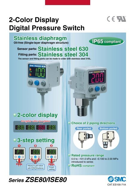
2-Color DisplayDigital Pressure SwitchStainless diaphragmOil-free (Single-layer diaphragm structure)Sensor parts: Stainless steel 630Fitting parts: Stainless steel 304The sensor and fitting parts can be made to order with stainless steel 316L.IP65 compliant2-color displayIrregular value at a glanceChoice of 2 piping directionsRear portedBottom ported3-step setting123PushAdjust to set-valuewith buttons.PushFinishsettingRated pressure range0.0 to –101.0 kPa and –0.100 to 2.00 MPaintroduced to seriesRoHS compliantSeries ZSE80/ISE80CAT.ES100-71A
Leakage1 x 10 -10 Pa·m 3 /s1 x 10 -5 Pa·m 3 /s Sensor and fitting parts are electron-beam welded. Choice of VCR ® or Swagelok ® fitting is available.VCR ®compliantSwagelok ®compliantConfirmation of theatmospheric pressureof a load lock chamberApplicable Fluid Examples Water Hydraulic fluid (JIS-K2213) Silicon oil (JIS-K2213) Lubricant (JIS-K6301) FluorocarbonConfirmation ofadsorption of workpieces containingmoistureConfirmation of supplypressure of cleaning lines∗ VCR ® and Swagelok ® are registered trademarks of Swagelok Company. Argon Ammonia Carbon dioxide Air-containing drainage NitrogenApplicationsConfirmation of workingpressure ofhydrauliccylinderConfirmation of pressureafter lubricator unitRestrictor installed fitting type (-X510) Made to OrderA pressure switch that has a restrictor installed in the fitting is available so that it prevents thesensor from being damaged by water collision with rush inertia. (Refer to page 12 for detail.)SeriesZSE80VariationsZSE80FISE80ISE80HEasy colordistinction bypressurerangeOUT1OUT2OUT1OUT2OUT1OUT2OUT1OUT20.0 to –101.0 kPa–100.0 to 100.0 kPa–0.100 to 1.000 MPa–0.100 to 2.00 MPa2 MPa1 MPaRated pressure range100 kPa0–101 kPa0–100 kPa0–0.1 MPa(-100 kPa)0–0.1 MPa(-100 kPa)Withstand pressureMinimum unit settingRepeatabilityFeatures 1500 kPa 2 MPa 4 MPa0.1 kPa 0.001 MPa±0.2%F.S. ±1 digit
2-color display (LCD)Can select from 4 indicatorpatterns of color combinations.1234ONRedGreenRedGreenOFFGreenRedRedGreenPipingRc1/8 (female threaded) is now available. R1/4 (M5 x 0.8 female threaded) NPT1/4 (M5 x 0.8 female threaded) G1/4 (M5 x 0.8 female threaded)Rc1/8 URJ1/4 (VCR® fitting compliant) TSJ1/4 (Swagelok® fitting compliant)Output displayIt lights when OUT1 or OUT2 outputs.Convex rubber buttonConvex button is adopted andprovides IP65 rating.Improved maneuverability andoperability.Lead wire length 2 m (Standard) 3 m (Made to Order)OutputAnalog current output is newly added. Advantageous when it is wired for a long distance. It is resistant against noise. NPN open collector 1 output PNP open collector 1 output NPN open collector 2 outputs PNP open collector 2 outputs NPN open collector 2 outputs + Analog voltage output/Auto-shift switching PNP open collector 2 outputs + Analog voltage output/Auto-shift switching NPN open collector 2 outputs + Analog current output/Auto-shift switching PNP open collector 2 outputs + Analog current output/Auto-shift switching Secret code settingThis ensures that only authorized persons can operate the switchwhen the key is locked.OUT1OUT2Input an arbitrarythree-digit value.∗ The set-value can be confirmed even when the key is locked. Power-saving modeTurning off the display can save power consumption.(Power consumption: Max. 18% reduced) Resolution switching functionIt prevents minor variation of the indicated value.OUT1OUT21/10001/100(Only the indicated value changes without changing precision.) MPa/kPa switching functionThe indication unit for vacuum, compound pressure andpositive pressure can be integrated into either MPa or kPa.OUT1OUT2OUT1OUT2The numerical valuedisappears and thedecimal points blink.OUT1OUT2OUT1OUT2Front protection coverPanel mountSuitable for side-by-side mounting Requires less installation space andpanel cutting.40Bracket mountBracketOnly one openingBracketFeatures 2
2-Color Display Digital Pressure SwitchFor General FluidsSeries ZSE80/ISE80How to OrderFor positivepressure ISE 80 02 NFor vacuum/compound pressureNPABRTSV02N02F02C01A2B202LRated pressure range80 –0.1 to 1 MPa80H –0.1 to 2 MPaZSE 80 02 NRated pressure range80 0 to –101 kPa80F –100 to 100 kPaR1/4(M5 female threaded)NPT1/4(M5 female threaded)G1/4(M5 female threaded)Rc1/8URJ1/4TSJ1/4R1/4(M5 female threaded)PipingRear portedBottom portedNPT1/4N02L(M5 female threaded)C01L Rc1/8A2L URJ1/4B2L TSJ1/4Input/OutputNPN open collector 1 outputPNP open collector 1 outputNPN open collector 2 outputsPNP open collector 2 outputsNPN open collector 2 outputs + Analog voltage output/Auto-shift switchingPNP open collector 2 outputs + Analog voltage output/Auto-shift switchingNPN open collector 2 outputs + Analog current output/Auto-shift switchingPNP open collector 2 outputs + Analog current output/Auto-shift switchingTable 1Made to OrderMMNilABCMade to OrderRefer to Table 1 below.Option 1NilMPOption 3SymbolWith unit display Note 1)switching functionFixed SI unit Note 2)Initial value PSINoneWith bracketWith bracket Note)Panel mountOperating Note) Calibrationmanual certificate (Booklet) —— — (CD-ROM) —SymbolNilKYTWRNote) All texts in both English and JapaneseRear ported (Booklet)— (CD-ROM)CalibrationcertificateNote 1) Under the New Measurement Law,sales of switches with the unitswitching function have not beenallowed for use in Japan.Note 2) Fixed unit ISE80H: MPaOthers : MPa, kPaZS-24-AZS-24-DOperating Note)manualBottom portedOption 2ZS-35-AZS-35-BSymbol-X500 Note)-X501-X510Note) Not applicable to the rated pressure range 0 to 2MPa specification. Refer to page 12 for detail.Option1SpecificationsWetted parts: Stainless steel 316LLead wire length 3 mRestrictor installed fittingOptionBracketPanel mountPanel mount + Front protection coverPiping directionRear portedRear portedBottom portedRear portedBottom portedRear portedBottom portedPart no.ZS-24-AZS-24-DZS-35-AZS-35-CZS-35-BZS-35-FZS-35-EZS-35-CRear portedPanel mount + Front protection coverDZS-35-FRear portedNote) Rear ported onlyBottom portedBottom portedZS-35-E
2-Color Display Digital Pressure SwitchFor General FluidsSeries ZSE80/ISE80SpecificationsRated pressure rangeSet pressure rangeWithstand pressureWetted parts materialApplicable fluidPort sizePower supply voltageCurrent consumptionSwitchoutputRepeatabilityHysteresisAnalogoutputAuto-shift inputDisplayDisplay accuracyIndicator lightFunctionEnvironmentresistanceModelTemperature characteristicsLead wireMaximum load currentMaximum load voltageResidual voltageResponse timeShort circuit protectionHysteresis modeWindow comparator modeVoltageoutputCurrentoutputStandards∗ G1/4 is available for rear ported only.EnclosureOperating temperature rangeOperating humidity rangeWithstand voltageInsulation resistanceVibration resistanceImpact resistanceOutput voltage(Rated pressure range)LinearityOutput impedanceOutput current(Rated pressure range)LinearityLoad impedanceZSE80(Vacuum pressure)ISE80(Positive pressure)–0.100 to 1.000 MPa–0.105 to 1.100 MPa2 MPa0.0 to –101.0 kPa –100.0 to 100.0 kPa–0.100 to 2.00 MPa10.0 to –111.0 kPa –110.0 to 110.0 kPa–0.105 to 2.20 MPa500 kPa4 MPaPressure sensor: Stainless steel 630, Fitting: Stainless steel 304Fluids do not corrode stainless steel 630 and 304R1/4, NPT1/4, G1/4 ∗ , URJ1/4, TSJ1/4, Rc1/8Piping direction: Rear/Bottom12 to 24 VDC ±10%, Ripple (p-p) 10% or less (with power supply polarity protection)45 mA or lessNPN 1 output, NPN 2 outputs, PNP 1 output, PNP 2 outputs80 mA28 V (at NPN output)1 V or less (with load current of 80 mA)2.5 ms (with anti-chattering function: 20, 100, 500, 1000, 2000 ms)Yes±0.2% F.S. ±1 digit1 to 5 V ±2.5% F.S.4 to 20 mA ±2.5% F.S.ZSE80F(Compound pressure)Variable (0 or above)±1% F.S. or lessApprox. 1 kΩ±1% F.S. or less2.4 to 20 mA±2.5% F.S.Maximum load impedance: 300 Ω (Power supply voltage 12 V)600 Ω (Power supply voltage 24 V)Minimum load impedance: 50 ΩNon-voltage input (Reed or Solid state), Low level: 0.4 V or less, 5 ms or longer input3 1/2-digit, 7-segment, 2-color LCD (Red/Green)±2% F.S. ±1 digit (Ambient temperature of 25 ±3°C)Lights up when output is turned ON. OUT1, OUT2: OrangeAnti-chattering, Zero-out, Key lock function, Auto-preset, Auto-shift,Unit display switching, Power-saving modeIP65Operating: 0 to 50°C, Stored: –10 to 60°C (No freezing or condensation)Operating/Stored: 35 to 85% RH (No condensation)250 VAC for 1 minute between live parts and case2 MΩ or more between live parts and case (at 50 VDC Mega)10 to 150 Hz at whichever is smaller of 1.5 mm amplitude or 20 m/s 2 acceleration,in X, Y, Z directions, for 2 hours each (De-energized)100 m/s 2 in X, Y, Z directions, 3 times each (De-energized)±3% F.S. (Based on 25°C, within operating temperature range)Oilproof heavy-duty vinyl cable, 3 cores (N.P)4 cores (A.B)5 cores (R.T.S.V)CE marking, UL/CSA, RoHS complianceISE80H(Positive pressure)0.6 to 5 V ±2.5% F.S. 0.8 to 5 V ±2.5% F.S.3.2 to 20 mA±2.5% F.S.ø3.5, 2 mConductor area: 0.15 mm 2 (AWG26)Insulator O.D.: 0.95 mmPiping SpecificationsModelPort sizeWeight (Bottom ported)Weight (Rear ported)Leakage02R1/4117 g89 gN02NPT1/4F02G1/4C01Rc1/8A2URJ1/4B2TSJ1/4118 g—114 g120 g111 g90 g86 g86 g92 g83 g1 x 10 –5 Pa·m 3 /s 1 x 10 –10 Pa·m 3 /s2
Series ZSE80/ISE80Analog OutputVoltage outputAnalog output [V]510.6A BCCurrent outputAnalog output [mA]2042.4Pressure A BCRangeFor vacuumpressureFor compoundpressureFor positivepressureRated pressure range0.0 to –101.0 kPaA10.1 kPaB0C–101.0 kPa–100.0 to 100.0 kPa — –100.0 kPa 100.0 kPa–0.100 to 1.000 MPa–0.100 to 2.00 MPa–0.100 MPa–0.100 MPa Note) 00Note) Analog output is 0.8 [V] or 3.2 [mA] at the pressure A.Pressure1.000 MPa2.00 MPaDescriptionsOutput (OUT1) display (Orange)Lights up when OUT1 is turned ON.Output (OUT2) display (Orange)Lights up when OUT2 is turned ON.buttonUse this button to select the mode or increase theON/OFF set-value.It is also used for switching to the peak displaymode.LCDDisplays the current pressure, set mode, selecteddisplay unit, and error code. Always use red orgreen display; or switch between green and redaccording to the output. Four different displaysettings are available.SET buttonUse this button to change the mode or confirm theset-value.buttonUse this button to select the mode or decrease theON/OFF set-value.It is also used for switching to the bottom displaymode.3
2-Color Display Digital Pressure SwitchFor General FluidsSeries ZSE80/ISE80Internal Circuits and Wiring Examples-NNPN (1 output)-PPNP (1 output)-ANPN (2 outputs)Brown DC (+)Brown DC (+)Brown DC (+)Main circuitLoadBlack OUT+–12 to24 VDCMain circuitBlack OUTLoad+–Main circuit12 toLoad+24 VDC Black OUT1 Load –White OUT212 to24 VDCBlue DC (–)Blue DC (–)Blue DC (–)Max. 28V, 80 mAResidual voltage 1 V or lessMax. 80 mAResidual voltage 1 V or lessMax. 28V, 80 mAResidual voltage 1 V or less-BPNP (2 outputs)-RNPN (2 outputs) +Analog voltage output-R/-SNPN (2 outputs) +Auto-shift inputMain circuitBrown DC (+)Black OUT1+Load –White OUT2Load12 to24 VDCMain circuitBrown DC (+)Gray Analog outputLoad+Black OUT1Load –White OUT2Load12 to24 VDCMain circuitBrown DC (+)Gray Auto-shift inputLoad+Black OUT1Load –White OUT212 to24 VDCBlue DC (–)Blue DC (–)Blue DC (–)Max. 80 mAResidual voltage 1 V or lessMax. 28V, 80 mAResidual voltage 1 V or lessMax. 28V, 80 mAResidual voltage 1 V or less-SNPN (2 outputs) +Analog current output-TPNP (2 outputs) +Analog voltage output-T/-VPNP (2 outputs) +Auto-shift inputBrown DC (+)Brown DC (+)Brown DC (+)Main circuitGray Analog outputLoad+Black OUT1Load –White OUT2Load12 to24 VDCMain circuitGray Analog outputLoad+Black OUT1Load –White OUT2Load12 to24 VDCMain circuitGray Auto-shift inputBlack OUT1+Load –White OUT2Load12 to24 VDCBlue DC (–)Blue DC (–)Blue DC (–)Max. 28V, 80 mAResidual voltage 1 V or lessMax. 80 mAResidual voltage 1 V or lessMax. 80 mAResidual voltage 1 V or less-VPNP (2 outputs) +Analog current outputBrown DC (+)Main circuitMax. 80 mAResidual voltage 1 V or lessGray Analog outputLoad+Black OUT1Load –White OUT2LoadBlue DC (–)12 to24 VDC4
Series ZSE80/ISE80DimensionsZSE/ISE8- 02N02F02C01A2B230226.249.6(N02: 50.1)8.45M5 x 0.8 thread depth 5203010Piping port02: R1/4N02: NPT1/4ø3.58.8 Atmospheric vent port ø2.62214.7202 x M3 x 0.5 thread depth 4Widthacrossflats 17246.226.28.4525.112.410.1Piping portRc1/8Piping portG1/4ø14.5-C01: Rc1/8-F02: G1/48.4527.78.4521.7Piping portURJ1/4Piping portTSJ1/45-A2: URJ1/4-B2: TSJ1/4
2-Color Display Digital Pressure SwitchFor General FluidsSeries ZSE80/ISE80DimensionsZSE/ISE8- 02LN02LC01LA2LB2L302 4125.22010 3060.5(N02L: 61.5)202 x M3 x 0.5thread depth 4ø3.5Piping port02L: R1/4N02L: NPT1/48.8Atmospheric vent port ø2.624125.249.564.858.810.329.5M5 x 0.8 thread depth 5Widthacrossflats 17Piping portRc1/8Piping portURJ1/4Piping portTSJ1/4-C01L: Rc1/8-A2L: URJ1/4-B2L: TSJ1/46
Series ZSE80/ISE80DimensionsWith bracket (Rear ported)A• ZS-24-A3020551.6 204039.743.21511.5ø4.5204.56.5With bracket (Rear ported)• ZS-24-D30View A205040304 x ø4.549432016.335.54725.2260.5103020551.6 204043.21511.54.27.2 7.5221.54.539.7With bracket (Bottom ported)ø3.5740.3
2-Color Display Digital Pressure SwitchFor General FluidsSeries ZSE80/ISE80DimensionsPanel mount (Rear ported)407.556.125.251.238.6Panel-cut dimensions36±0.336 x n pcs. + 4 x (n pcs. – 1)36±0.3364 x R3or less67 or more4 x R3 or less8
Series ZSE80/ISE80DimensionsPanel mount (Bottom ported)407.55024.236±0.336 x n pcs. + 4 x (n pcs. – 1)36±0.33671.151.238.6Panel-cut dimensions4 x R3 or less 4 x R3 or less9
2-Color Display Digital Pressure SwitchFor General FluidsSeries ZSE80/ISE80Function DetailsA Auto-shift function (F4)When there are large fluctuations in the supply pressure, the switchmay fail to operate correctly. The auto-shift function compensatessuch supply pressure fluctuations. It measures the pressure at thetime of auto-shift signal input and uses it as the reference pressureto correct the set-value on the switch.Set-value correction by auto-shift function(Differential)PressureSwitchoutput1·(2)P-1(P-3)ONOFFH-1(H-2)Supply pressurenormalSupply pressuredropRectified value∗Supply pressureincreaseRectifiedvalue∗F in brackets stand for the function codes. Refer to the operatingmanual for how to operate and function codes in detail.B Auto-preset function (F8)Auto-preset function, when selected in the initial setting, calculatesand stores the set-value from the measured pressure.The optimum set-value is determined automatically by repeating vacuumand break with the target workpiece several times.Suction VerificationHighVacuumMax. AP-1n-1Min. BAtmosphereH-1SuctionWork 1 Work 2ReleasedWork 1 Work 2 Work nWork nAuto-shiftinputHiLoAB Switch output5 ms or more 10 ms or less response timewhen autoshiftis input.Formula for Obtaining the Set-ValueP_1 or P_2P_1 (P_2) = A – (A-B)/4n_1 (n_2) = B + (A-B)/4H_1 or H_2H_1 (H_2) = (A-B)/2∗ Rectified valueWhen the auto-shift is selected, “ooo” will be displayed for approximately1 second, and the pressure value at that point will be savedas a rectified value “C_5”. Based on the saved rectified values, theset-value Note) of “P_1”, “H_1”, “P_2”, and “H_2” will likewise be rectified.Note) When an output is reversed, “n_1”, “H_1”, “n_2”, “H_2” will berectified.Possible Set Range for Auto-Shift InputRegulating pressure rangeCompound pressure –110.0 to 110.0 kPaVacuum pressure 10.0 to –111.0 kPa–0.105 to 1.100 MPaPositive pressure–0.105 to 2.20 MPaPossible set range–220 to 220 kPa121.0 to –121.0 kPa–1.205 to 1.205 MPa–2.31 to 2.31 MPaAuto-shift zeroThe basic function of auto-shift zero is the same as the function forauto-shift. Also, it corrects values on the display, based on a pressurevalue of 0, when the auto-shift is selected.C Precision indicator setting function (F7)Fine adjustment of the indicated value can be made within the rangeof ±5% of the read value. The scattering of the indicated value canbe eliminated.Display pressure value±5% R.D.+0 Applied pressureDisplayed value at the time of shipmentAdjustable range of display calibration functionNote) When the precision indicator setting function is used, the set pressurevalue may change ±1 digit.D Peak and bottom display functionThis function constantly detects and updates the maximum (minimum)value and allows to hold the maximum (minimum) pressurevalue.When the buttons are simultaneously pressed for 1 second orlonger, while “holding”, the hold value will be reset.E Key lock functionThis function prevents incorrect operations such as accidentally changingthe set-value.F Zero-out functionThis function clears and resets the zero value on the display ofmeasured pressure.For the pressure switch with analog output, the analog output shiftsaccording to the indication. A displayed value can be adjusted within±10% F.S. of the pressure when ex-factory.10
Series ZSE80/ISE80Function DetailsG Error indication functionErrornameOvercurrenterrorResidualpressure errorAppliedpressure errorAuto-shifterrorSystem errorError codeInternal data errorInternal data errorInternal data errorH Anti-chattering function (F3)DescriptionLoad current of switch output (OUT1) exceeds 80mA.Load current of switch output (OUT2) exceeds 80mA.It is still applied with pressure that is ±10% over theatmospheric pressure and the upper limit of therated pressure range when it is cleared to zero.∗ After displaying the error code for 1 second, theswitch automatically returns to the measuringmode. Due to individual product differences, thesetting range varies ±1 digits.Supply pressure exceeds the maximum setpressure.Supply pressure is below the minimum setpressure.The value measured at the time of auto-shift input isoutside the set pressure range.∗ After displaying the error code for one second, theswitch returns to the measuring mode.A large bore cylinder or ejector consumes a large volume of air inoperation and may experience a temporary drop in the supply pressure.This function prevents detection of such temporary drops in thesupply pressure as an error.Available response time settings20 ms, 100 ms, 500 ms, 1000 ms, 2000 msThis function averages pressure values measured during the responsetime set by the user and then compares the average pressurevalue with the pressure set point value to output the result onthe switch.Pressure ↑Momentary changeI Unit display switching function (F0)Display units can be switched with this function.JPressurerangeApplicablepressuresensorSet pressurerangekPaMPakgf/cm 2barpsiinHgmmHgFor compoundpressureZSE80F–110 to110 kPa0.1Power-saving mode (F9)ForvacuumpressureZSE80K Secret code setting (F10)—0.0010.0010.020.1110 to–111 kPa0.1—0.0010.0010.020.11Forpositive pressure1ISE80–0.1 to1.1 MPa0.0010.010.010.1——ISE80H ∗–0.1 to2.2 MPa10.0010.010.01∗ ISE80H: Does not indicate the last digit when the pressure is 2.000 MPa or higher.OUT1OUT2The numerical valuedisappears and thedecimal points blink.Power-saving mode can be selected.It shifts to the power-saving mode without button operation for 30seconds. It is set to the normal mode (Power-saving mode is OFF.)when ex-factory. (Decimal points and operation indicator light (onlywhen the switch output is turned ON.) blink in the power-savingmode.)OUT1OUT2Input an arbitrarythree-digit value.∗ The set-value can be confirmed when the key is locked.It can be set whether code number input is required or not when keyis locked. It is set to input no code number when ex-factory.1——Pressure rangeP-1H-1t (ms) t (ms) Time →Switch outputoperation in ONnormalconditions OFFSwitch outputoperation when ONanti-chatteringfunction is on. OFFTime →Time →11
Series ZSE80/ISE80Made to OrderPlease contact <strong>SMC</strong> for detailed dimensions, specifications, and lead times.1Wetted parts: Stainless steel 316L2Lead wire length 3 mThis pressure switch has better corrosion resistance that usesstainless steel 316L for the wetted parts (pressure sensor and fitting).It has a lead wire extended to 3 meters.How to Order∗ Refer to How to Order on page 1for standard specifications.How to Order∗ Refer to How to Order on page 1for standard specifications.ZSE80(F)/ISE80X500ZSE80(F)/ISE80(H)X501Piping ∗ Output ∗ Option ∗Piping ∗ Output ∗ Option ∗Note 1) Not applicable to the rated pressure –0.1 to 2 MPa specifications (ISE80H).Note 2) A restrictor (equivalent to -X510) is installed inside the fitting. (Pipingspecifications A2(L) and B2(L) are excluded.)SpecificationsModelZSE80(F)ISE80Withstand pressure 500 kPa1.5 MPaApplicable fluid Fluids do not corrode stainless steel 316LModels other than above are the same specifications as standard.3Restrictor installed fittingA restrictor is installed inside the fitting in order to improve enduranceof water collision with rush inertia in the piping when adsorptionis broken.How to OrderZSE80(F)/ISE80(H)X510PipingOutputOptionRestrictorWithout restrictorMade to Order “-X510”StandardNote 1) Not applicable for piping specifications A2(L) and B2(L).Note 2) Sometimes does not work for suppression of water hammer effect even if thisproduct is used. Take other measures in such a case.12
Back page 1Series ZSE80/ISE80Safety InstructionsThese safety instructions are intended to prevent a hazardous situation and/or equipment damage. Theseinstructions indicate the level of potential hazard by labels of "Caution", "Warning" or "Danger". Toensure safety, be sure to observe ISO 4414 Note 1) , JIS B 8370Note 2)and other safety practices.Explanation of the LabelsLabelsDangerWarningExplanation of the labelsIn extreme conditions, there is a possible result of serious injury or loss of life.Operator error could result in serious injury or loss of life.Caution Operator error could result in injury Note 3) or equipment damage.Note 4)Note 1) ISO 4414: Pneumatic fluid power – General rules relating to systemsNote 2) JIS B 8370: General Rules for Pneumatic EquipmentNote 3) Injury indicates light wounds, burns and electrical shocks that do not require hospitalization or hospital visits for long-term medical treatment.Note 4) Equipment damage refers to extensive damage to the equipment and surrounding devices.Selection/Handling/Applications1. The compatibility of the pneumatic equipment is the responsibility of the person who designs thepneumatic system or decides its specifications.Since the products specified here are used in various operating conditions, their compatibility for the specific pneumatic systemmust be based on specifications or post analysis and/or tests to meet the specific requirements. The expected performance andsafety assurance are the responsibility of the person who has determined the compatibility of the system. This person shouldcontinuously review the suitability of all items specified, referring to the latest catalog information with a view to giving dueconsideration to any possibility of equipment failure when configuring a system.2. Only trained personnel should operate pneumatically operated machinery and equipment.Compressed air can be dangerous if handled incorrectly. Assembly, handling or repair of pneumatic systems should beperformed by trained and experienced operators. (Understanding JIS B 8370 General Rules for Pneumatic Equipment, and othersafety rules are included.)3. Do not service machinery/equipment or attempt to remove components until safety is confirmed.1. Inspection and maintenance of machinery/equipment should only be performed once measures to prevent falling or runawayof the driven objects have been confirmed.2. When equipment is removed, confirm that safety process as mentioned above. Turn off the supply pressure for this equipmentand exhaust all residual compressed air in the system, and release all the energy (liquid pressure, spring, condenser, gravity).3. Before machinery/equipment is restarted, take measures to prevent quick extension of a cylinder piston rod, etc.4. If the equipment will be used in the following conditions or environment, please contact <strong>SMC</strong> first andbe sure to take all necessary safety precautions.1. Conditions and environments beyond the given specifications, or if product is used outdoors.2. Installation on equipment in conjunction with atomic energy, railway, air navigation, vehicles, medical equipment, food andbeverages, recreation equipment, emergency stop circuits, clutch and brake circuits in press applications, or safety equipment.3. An application which has the possibility of having negative effects on people, property, requiring special safety analysis.4. If the products are used in an interlock circuit, prepare a double interlock style circuit with a mechanical protection function forthe prevention of a breakdown. And, examine the devices periodically if they function normally or not.Exemption from Liability1. <strong>SMC</strong>, its officers and employees shall be exempted from liability for any loss or damage arising out ofearthquakes or fire, action by a third person, accidents, customer error with or without intention, productmisuse, and any other damages caused by abnormal operating conditions.2. <strong>SMC</strong>, its officers and employees shall be exempted from liability for any direct or indirect loss or damage,including consequential loss or damage, loss of profits, or loss of chance, claims, demands, proceedings,costs, expenses, awards, judgments and any other liability whatsoever including legal costsand expenses, which may be suffered or incurred, whether in tort (including negligence), contract,breach of statutory duty, equity or otherwise.3. <strong>SMC</strong> is exempted from liability for any damages caused by operations not contained in the catalogsand/or instruction manuals, and operations outside of the specification range.4. <strong>SMC</strong> is exempted from liability for any loss or damage whatsoever caused by malfunctions of its productswhen combined with other devices or software.
Series ZSE80/ISE80Specific Product Precautions 1Be sure to read this before handling.Refer to the back of page 1 for Safety Instructions and “Precautions for HandlingPneumatic Devices” (M-03-E3A) for Pressure Switches Precautions.HandlingWarning1. Do not drop, bump, or apply excessive impacts (980 m/s 2 ) whilehandling. Although the body of the sensor may not be damaged,the internal parts of the sensor could be damaged and lead to amalfunction.2. The tensile strength of the cord is 49 N. Applying a greater pullingforce on it can cause a malfunction. When handling, hold thebody of the sensor ––do not dangle it from the cord.3. Do not exceed the screw-in torque of 13.6 N·m when connectingthe pipe to the switch. Exceeding these values may causethe switch to malfunction.4. Do not use pressure sensors with corrosive and/or flammablegases or liquids.WarningConnection1. Incorrect wiring can damage the switch and cause a malfunctionor erroneous switch output.2. Connections should be done while the power is turned off.3. Wire separately from power lines and high voltage lines, avoidingwiring in the same conduit with these lines. Malfunctionsmay occur due to noise from these other lines.4. If a commercial switching regulator is used, make sure that theF.G. terminal is grounded.WarningCautionOperating Environment1. This pressure switch is CE marked; however, it is not equippedwith surge protection against lightning. Lightning surge countermeasuresshould be applied directly to system components asnecessary.2. This pressure switch does not have an explosion proof rating.Never use in the presence of an explosive gas as this maycause a serious explosion.1. Do not use this product in an environment that gives oil or solventsplash over it.2. When this pressure switch is used in a place where water anddust splash on, water and dust may enter inside the switchthrough the atmospheric vent port. Insert a ø4 tube (I.D. ø2.5)into the atmospheric vent port, and bring piping of the oppositeside up to the safe position to keep it from water and dust. Donot bend the tubing or close the hole of it. It causes malfunctionwith the measurement of positive pressure.TubeAtmosphericvent portTo the safe position to keepfrom water and/or dust.TubeAtmosphericvent portTo the safe position to keepfrom water and/or dust.∗ Make sure that the tubing is inserted to the end of the atmosphericvent port.∗ Use <strong>SMC</strong> tubing, TU0425 (Material: Polyurethane, Tubing O.D.ø4, I.D. ø2.5).Operating EnvironmentCaution3. Some fluids may generate static electricity when resin piping isused for piping. Take measures against static electricity withequipment when this switch is used in connection with resin piping.Also, the ground should be separate from that of the unitsthat generate strong electromagnetic noise or high frequency,otherwise, the switch can be damaged by static electricity.WarningPressure Source1. Use of poisonous and deleterious substance, corrosiveor flammable gas.The materials used for the pressure sensor and the fitting ofthis switch are stainless steel 630, stainless steel 304 andstainless steel 316L (made to order). Do not use fluids such aspoisonous, deleterious substance and corrosive gas.The switch is not protected against explosion. Do not use itwith flammable gas, either.2. Fluid compatibilityThe fluid contact areas are stainless steel 630 (pressure sensor),stainless steel 304 (fitting), stainless steel 316L (pressuresensor, fittings, made to order). Use fluid that will not corrodethe materials.(For corrosiveness of fluid, consult with the manufacturer ofthe fluid.)3. Intrusion of water and drainA pressure sensor of stainless steel diaphragm is used for thisswitch. The pressure sensor of this switch can be damaged bythe rush inertia of water when the drain contained in water andair collide with the pressure sensor when vacuum is broken aftervacuum adsorption is confirmed, and it may cause malfunctionwith the pressure indication. If there is a possibility ofwater or drainage getting in, narrow the diameter of the pipingto the pressure switch, or make an orifice in the middle of thepiping. Extra attention is needed when the rear surface pipingtype model is used.4. Withstand pressureWhen liquid fluid is used, rapid pressure change can be generatedsuch as water hammer and surge pressure when a valveis turned ON/OFF.Install a dumper or an absorber or an accumulator as a countermeasureaccording to necessity.It may damage the pressure sensor or the switch if pressureHelium leakage testHelium leakage test is conducted on the welding parts. Use a ferruleby Swagelok (Swagelok ® fittings) as the TSJ fittings andpacking, ground, etc. by Swagelok (VCR ® fittings) as the URJ fittings.If a ferrule, packing or ground by other manufacturers areto be used, conduct helium leakage test before using those products.∗ Swagelok ® and VCR ® are registered trademarks of SwagelokCompany.Back page 2
Series ZSE80/ISE80Specific Product Precautions 2Be sure to read this before handling.Refer to the back of page 1 for Safety Instructions and “Precautions for HandlingPneumatic Devices” (M-03-E3A) for Pressure Switches Precautions.Caution1. Mounting with panel mount adapterFront protection cover (Option)MountingFront protection cover (Option)PanelPanelPanel mountadapter APanel mountadapter APanel mountadapter BPanel mountadapter B2. Mounting with bracketsMount a bracket to the using two M3 x 5L mounting screws and install on piping. The switch can be installed horizontally dependingon the installation location.Mounting screw M3 x 5LMounting screw M3 x 5LBracket ABracket BThe tightening torque for bracket mountingscrew should be 0.98 N·m or less.CautionSet Pressure Range and Rated Pressure RangeSet the pressure within the rated pressure range.The set pressure range is the range of pressure that is possible in setting.The rated pressure range is the range of pressure that satisfies the specifications (accuracy, linearity, etc.) on the switch.Although it is possible to set a value outside the rated pressure range, the specifications will not be guaranteed even if the value stays withinthe set pressure range.SwitchPressure range–100 kPa 0 100 kPa 1 MPa 2 MPaFor vacuumpressureZSE80–101 kPa–111 kPa010 kPaFor compoundpressureZSE80F–110 kPa–100 kPa100 kPa110 kPaFor positivepressureISE80ISE80H–0.1 MPa1 MPa–0.105 MPa 1.1 MPa–0.1 MPa–0.105 MPa2 MPa2.2 MPaBack page 3Rated pressure range of switchSet pressure range of switch
<strong>SMC</strong>'S GLOBAL MANUFACTURING, DISTRIBUTIONAND SERVICE NETWORKEUROPEAUSTRIA<strong>SMC</strong> Pneumatik GmbH (Austria)BELGIUM<strong>SMC</strong> <strong>Pneumatics</strong> N.V./S.A.BULGARIA<strong>SMC</strong> Industrial Automation Bulgaria EoodCROATIA<strong>SMC</strong> Industrijska Automatika d.o.o.CZECH REPUBLICNORWAY<strong>SMC</strong> <strong>Pneumatics</strong> Norway ASPOLAND<strong>SMC</strong> Industrial Automation Polska Sp.z.o.o.ROMANIA<strong>SMC</strong> Romania S.r.l.RUSSIA<strong>SMC</strong> Pneumatik LLCSLOVAKIA<strong>SMC</strong> Priemyselná Automatizácia Spol s.r.o.SINGAPORE<strong>SMC</strong> <strong>Pneumatics</strong> (S.E.A.) Pte. Ltd.SOUTH KOREA<strong>SMC</strong> <strong>Pneumatics</strong> Korea Co., Ltd.TAIWAN<strong>SMC</strong> <strong>Pneumatics</strong> (Taiwan) Co., Ltd.THAILAND<strong>SMC</strong> (Thailand) Ltd.NORTH AMERICA<strong>SMC</strong> Industrial Automation CZ s.r.o.SLOVENIACANADADENMARK<strong>SMC</strong> Industrijska Avtomatika d.o.o.<strong>SMC</strong> <strong>Pneumatics</strong> (Canada) Ltd.<strong>SMC</strong> Pneumatik A/SSPAIN/PORTUGALMEXICOESTONIA<strong>SMC</strong> España S.A.<strong>SMC</strong> Corporation (Mexico), S.A. de C.V.<strong>SMC</strong> <strong>Pneumatics</strong> Estonia OÜSWEDENU.S.A.FINLAND<strong>SMC</strong> <strong>Pneumatics</strong> Sweden AB<strong>SMC</strong> Corporation of America<strong>SMC</strong> <strong>Pneumatics</strong> Finland OyFRANCE<strong>SMC</strong> Pneumatique SAGERMANYSWITZERLAND<strong>SMC</strong> Pneumatik AGU.K.<strong>SMC</strong> <strong>Pneumatics</strong> (U.K.) Ltd.SOUTH AMERICAARGENTINA<strong>SMC</strong> Argentina S.A.<strong>SMC</strong> Pneumatik GmbHBOLIVIAGREECEASIA<strong>SMC</strong> <strong>Pneumatics</strong> Bolivia S.r.l.<strong>SMC</strong> Hellas E.P.E.HUNGARY<strong>SMC</strong> Hungary Ipari Automatizálási Kft.IRELAND<strong>SMC</strong> <strong>Pneumatics</strong> (<strong>Ireland</strong>) Ltd.ITALY<strong>SMC</strong> Italia S.p.A.LATVIA<strong>SMC</strong> Pnuematics Latvia SIALITHUANIAUAB “<strong>SMC</strong> <strong>Pneumatics</strong>”NETHERLANDS<strong>SMC</strong> <strong>Pneumatics</strong> B.V.CHINA<strong>SMC</strong> (China) Co., Ltd.HONG KONG<strong>SMC</strong> <strong>Pneumatics</strong> (Hong Kong) Ltd.INDIA<strong>SMC</strong> <strong>Pneumatics</strong> (India) Pvt. Ltd.INDONESIAPT <strong>SMC</strong> <strong>Pneumatics</strong> IndonesiaMALAYSIA<strong>SMC</strong> <strong>Pneumatics</strong> (S.E.A.) Sdn. Bhd.PHILIPPINESShoketsu <strong>SMC</strong> CorporationBRAZIL<strong>SMC</strong> Pneumáticos do Brasil LtdaCHILE<strong>SMC</strong> <strong>Pneumatics</strong> (Chile) S.A.VENEZUELA<strong>SMC</strong> Neumatica Venezuela S.A.OCEANIAAUSTRALIA<strong>SMC</strong> <strong>Pneumatics</strong> (Australia) Pty. Ltd.NEW ZEALAND<strong>SMC</strong> <strong>Pneumatics</strong> (N.Z.) Ltd.Safety Instructions Be sure to read “Precautions for Handling Pneumatic Devices” (M-03-E3A) before using.Akihabara UDX 15F,4-14-1, Sotokanda, Chiyoda-ku, Tokyo 101-0021, JAPANPhone: 03-5207-8249 Fax: 03-5298-5362URL http://www.smcworld.com© 2007 <strong>SMC</strong> Corporation All Rights ReservedSpecifications are subject to change without prior noticeand any obligation on the part of the manufacturer.D-DN1st printing LW printing LW 13500DN Printed in Japan.This catalog is printed on recycled paper with concern for the global environment.