
You also want an ePaper? Increase the reach of your titles
YUMPU automatically turns print PDFs into web optimized ePapers that Google loves.
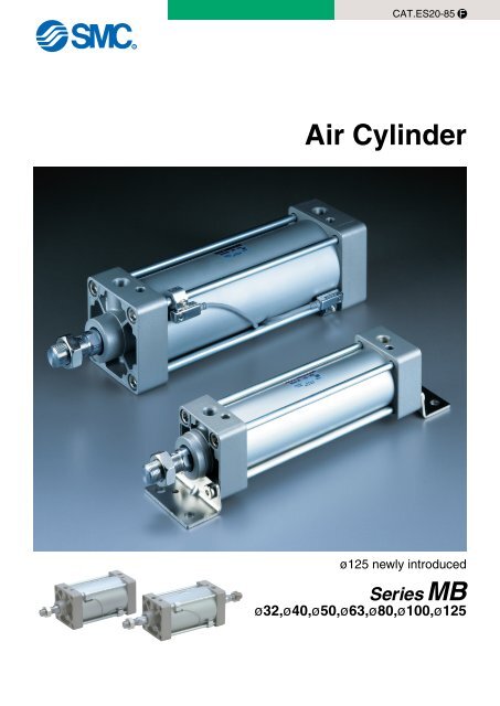
<strong>Series</strong> <strong>MB</strong>, <strong>MB</strong>W, <strong>MB</strong>K,Double acting single rodDouble acting double rodDouble acting non-rotating rodø125 newly introduced(Double acting single rod, Double acting double rod)Increased kineticenergy absorptionElevated cushion volume and the adoption of anew cushion seal design permit about 30% moreallowable kinetic energy over the CA1 series.In addition, service life of cushion seal is about 5times greater.Improved cushion capacity"Floating" cushion seal design eliminatespiston rod "bouncing" due to crackingpressure at beginning of stroke.Compact and lightweightdesignThe square cover is made more compact thanthe CA1 series. In addition, die cast covers yield10 to 25% weight reduction over the CA1 series.Minimal rod deflectionImproved bushing and piston rod dimensional accuracyachieves tighter clearances and reduced piston roddeflection.Accurate mountingThe cylinder cover and mounting bracketwith high dimensional accuracy simplifiesinstallation and extends service life.Features 1
<strong>MB</strong>Low frictionQ, <strong>MB</strong>BEnd lock styleø32, ø40, ø50, ø63, ø80,ø100, ø125Easy adjustment of cushion valveAdjustment of the cushion valve ismade with a hex. wrench allowingfor easy fine adjustment.The cushion valve is recessed inthe cover.PortDirect mounting type autoswitches can be fitted.Direct mounting type auto switchReed switch: D-Z7D-Z8Solid state switch: D-Y5D-Y6D-Y7Switch mounting bracketA direct mounting type auto switch is securedon the tie rod with a dedicated switch bracket.MiniaturizationReduces the amount the auto switchprotrudes from the cylinder.Tie rod mountingtype auto switch(Conventional)Direct mountingtype auto switchImproved operabilityAuto switch mounting and adjustment of the mountingposition can be made via the same direction.Tie rod mounting typeauto switch (Conventional)Two directionsDirect mountingtype auto switchOne directionMDB50Phillips headscrewdriverWatchmaker'sscrewdriverHexagon wrench(Width acrossflats: 2.5 mm)VariationsStandard/Double actingSingle rod<strong>Series</strong> <strong>MB</strong>Double rod<strong>Series</strong> <strong>MB</strong>W∗Nonrotatingrod<strong>Series</strong> <strong>MB</strong>KJIS SymbolJIS SymbolJIS Symbol∗ JIS SymbolLow friction<strong>Series</strong> <strong>MB</strong>Q∗End lock<strong>Series</strong> <strong>MB</strong>BBore3240506380100125Standard stroke (mm)Auto switchinventory control can be simplified.Auto switch inventory control in the field can be simplified because directmounting type auto switches are applicable to a wide variety of cylinders.50 100 150 200 300 400 50025 75 125 175 250 350 450 600 700 800 900 1000(1)(1)Built-in-magnetRod bootMountingBasicAxial footFront flangeRear flangeSingle clevisDouble clevisCenter trunnionBasicFootFlangeCenter trunnionBasicAxial footFront flangeRear flangeSingle clevisDouble clevisCenter trunnionBasicAxial footFront flangeRear flangeSingle clevisDouble clevisCenter trunnionBasicAxial footFront flangeRear flangeSingle clevisDouble clevisCenter trunnionAccessoriesStandardRod end nutOptionKnuckle joint pin PageClevis pin1Single knuckle jointDouble knuckle jointTrunnion pivot bracketDouble clevis pivot bracketStandardRod end nutOptionKuckle joint pinSingle knuckle jointDouble knuckle jointTrunnion pivotbracketPage13StandardRod end nutOptionKnuckle joint pin PageClevis pin19Single knuckle jointDouble knuckle jointTrunnion pivot bracketDouble clevis pivot bracketStandardRod end nutOptionKnuckle joint pin PageClevis pin23Single knuckle jointDouble knuckle jointTrunnion pivot bracketDouble clevis pivot bracketStandardRod end nutLocking release bolt(N only) PageOption29Knuckle joint pinClevis pinSingle knuckle jointDouble knuckle jointTrunnion pivot bracketDouble clevis pivot bracket∗ ø125 is not included in <strong>MB</strong>K, <strong>MB</strong>Q and <strong>MB</strong>B.Note 1) Standard stroke for <strong>MB</strong>K series is below 700.Features 2
Air Cylinder/Single Rod<strong>Series</strong> <strong>MB</strong>ø32, ø40, ø50, ø63, ø80, ø100, ø125How to OrderStandard<strong>MB</strong>L 32 50With auto switchBLFGCDTStyleBuilt-in magnetMountingBasic/Without bracketAxial footFront flangeRear flangeSingle clevisDouble clevisCenter trunnionSpecial functionMDBElectricalentryGrommetTerminalconduitGrommetL 32Bore size50Stroke (mm)Refer to page 2 for standard stroke table.Wiring(Output)3-wire(Equiv. to NPN)Load voltageDCAC5V —100V100V,200V12V —Y7BWAuto switch— Without auto switchApplicable Auto Switches/ For detailed specifications, please refer to Best <strong>Pneumatics</strong> Vol.2 page 5.3-2.Reed switchSolid state switchPort thread typeSymbol Type— RcTN NPTTF GDiagnostic indication(2-color display)Water resistance (2-color display)Diagnostic output (2-color display)Latch type diagnostic output(2-color display)Strong magnetic field resistance3240506380100125—YesTerminalconduit 2-wireDIN terminalDiagnostic indication (2-color display) Grommet3-wire (NPN)3-wire (PNP)Grommet—2-wire∗ Lead wire length 0.5m······ – (Example): A543m········· L (Example): A54L5m········· Z (Example): A54ZIndicator32mm40mm50mm63mm80mm100mm125mm3-wire (NPN)2-wireYes3-wire (NPN)3-wire (PNP)2-wire4-wire(NPN)2-wire—24V24V—24V5V,12V100V,200VNumber ofauto switches∗ Refer to table below for selection ofapplicable auto switch.∗ The auto switches for D-Z7, Z80, Y59, Y69, Y7 are included butunmounted.(Only the switch mounting brackets for the above models are mounted.)Rod boot/Cushion• Besides the above models, there are some other auto switches that are applicable. For detailed information, please refer to page 11.———— 100V,200V12V5V,12V12V5V,12V12V5V,12V——Auto switch modelTie rodmountingZ76Z73A54———A59WY59AY7PJ51Y59B——Y7NWY7PWY7BWY7BAF59FBandmounting———A33A34A44—————G39K39—————F5LF —P5DW —∗∗ Solid state switches marked with a "Rod bootCushionLead wire length ∗ (m)Pre-wired0.5 3 5connector(–) (L) (Z)—————————————JKNone—N Note 1)————————S3n——————————213nNylon tarpaulinHeat resistant tarpaulinBoth endsNoneNote 1) Model without air cushion is designedto include rubber bumpers. Theoverall length is longer than thecylinder with air cushions becausethe bumpers are attached to the bothsides of the piston as follows.ø32, ø40: +6mm, ø50, ø63: +8mm,ø80, ø100: +10mm, ø125: +12mm" are produced upon receipt of order.ApplicableloadIC circuit—IC circuit——IC circuit——RelayPLCPLCRelayPLCIC circuit—RelayIC circuit PLC1
Single Rod <strong>Series</strong> <strong>MB</strong>OrderMadeJIS SymbolDouble actingMade to OrderRefer to page 38 for made to orderproducts of series <strong>MB</strong>.Symbol Specifications/Descriptions—XA Change of rod end shape—XB5 Oversized rod cylinder—XB6 Heat resistant cylinder (150°C)—XB13 Low speed cylinder (5 to 50mm/s)—XC3 Special port position—XC4 With heavy duty scraper—XC5 Heat resistant cylinder (110°C)—XC6 Piston rod and rod end nut made of stainless steelTie rod, cushion valve, tie rod nut, etc.—XC7made of stainless steel—XC8 Adjustable stroke cylinder/Adjustable extend stroke—XC9 Adjustable stroke cylinder/Adjustable retract stroke—XC10 Dual stroke cylinder/Double rod—XC11 Dual stroke cylinder/Single rod—XC12 Tandem cylinder—XC14 Change of trunnion bracket mounting position—XC22 Fluorine rubber sealsDouble clevis pin and double knuckle—XC27pin made of stainless steel—XC29 Double knuckle joint with spring pin—XC30 Front trunnion—XC35 With coil scraperSpecificationsBore size (mm)ActionFluidProof pressureMax. operating pressureMin. operating pressureAmbient and fluid temperatureLubricationOperating piston speedAllowable stroke toleranceCushion Note 1)Thread tolerancePort size (Rc, NPT, G)32 40 50 63 80 100 125Double acting single rodAir1.5MPa1.0MPa0.05MPaWithout auto switch: –10 to 70°C (No freezing)With auto switch: –10 to 60°C (No freezing)Not required (Non-lube)50 to50 to 1000mm/s700mm/s+1.0+1.4+1.8up to 250: 0 , 251 to 1000: 0 ,1001 to 1500: 0Both ends (Air cushion)JIS class 21/8 1/4 1/4 3/8 3/8 1/2 1/2Basic, Foot, Front flange, Rear flange,MountingSingle clevis, Double clevis, Center trunnionNote 1) When requesting a cylinder without air cushion, cylinder utilizes rubber bumpers which increasescylinders overall length.Standard StrokeBore(mm)Standard stroke (mm)32 25, 50, 75, 100, 125, 150, 175, 200, 250, 300, 350, 400, 450, 50040 25, 50, 75, 100, 125, 150, 175, 200, 250, 300, 350, 400, 450, 50050 25, 50, 75, 100, 125, 150, 175, 200, 250, 300, 350, 400, 450, 500, 60063 25, 50, 75, 100, 125, 150, 175, 200, 250, 300, 350, 400, 450, 500, 60080 25, 50, 75, 100, 125, 150, 175, 200, 250, 300, 350, 400, 450, 500, 600, 700, 800100 25, 50, 75, 100, 125, 150, 175, 200, 250, 300, 350, 400, 450, 500, 600, 700, 800125 25, 50, 75, 100, 125, 150, 175, 200, 250, 300, 350, 400, 450, 500, 600, 700, 800Intermediate strokes are available. (No spacer is used.)AccessoriesStandardOptionMountingRod end nutClevis pinSingle knuckle jointDouble knuckle joint(with pin)Rod bootMaterial of Rod BootSymbolJKMounting Bracket Part No.BasicMaterial Max. ambient temp.Nylon tarpaulin 70°CHeat resistant tarpaulin 110°C ∗∗ Max. ambient temperature for rod boot itself.FootFrontflangeBoresize (mm)Foot Note 1)FlangeSingle clevisDouble clevis32<strong>MB</strong>-L03<strong>MB</strong>-F03<strong>MB</strong>-C03<strong>MB</strong>-D0340<strong>MB</strong>-L04<strong>MB</strong>-F04<strong>MB</strong>-C04<strong>MB</strong>-D0450<strong>MB</strong>-L05<strong>MB</strong>-F05<strong>MB</strong>-C05<strong>MB</strong>-D0563<strong>MB</strong>-L06<strong>MB</strong>-F06<strong>MB</strong>-C06<strong>MB</strong>-D06Note 1) Two foot brackets required for one cylinder.Note 2) Accessories for each mounting bracket are as follows.Foot, Flange, Single clevis: Mounting boltsDouble clevis: Clevis pin, Cotter pin → Refer to page 8 for details.Rearflange80<strong>MB</strong>-L08<strong>MB</strong>-F08<strong>MB</strong>-C08<strong>MB</strong>-D08Singleclevis100Doubleclevis<strong>MB</strong>-L10<strong>MB</strong>-F10<strong>MB</strong>-C10<strong>MB</strong>-D10Max.stroke70080012001200140015001500Centertrunnion— — — — — —125<strong>MB</strong>-L12<strong>MB</strong>-F12<strong>MB</strong>-C12<strong>MB</strong>-D122
<strong>Series</strong> <strong>MB</strong>Theoretical ForceBore size(mm)Rod diameter(mm)OperatingdirectionPiston area(mm 2 )324050638010012512162020253032OUTOUTOUTOUTOUTOUTOUT80412571963311750277854122721612513936231005157124542413775899351508235636823225037851247201131424909INININININININ6911056164928034536714711468138211330561907142922942073174958411361214434402764226601121181428594588Note) Theoretical force (N)=Pressure (MPa) X Piston area (mm 2 )Weight/Aluminum TubeBore size (mm)BasicFootFlangeBasic weightSingle clevisDouble clevisTrunnionAdditional weight per 50 stroke All mounting bracketSingle knuckle jointAccessoriesDouble knuckle joint (with pin)Additional weight to the basic weight ∗Square tubeAdditional weight per 50 stroke0.2Calculation example: <strong>MB</strong>B32-100 (Basic, ø32, 100st) Basic weight ·········· 0.50 (Basic, ø32) Additional weight ··· 0.11/50 stroke Cylinder stroke ······ 100 stroke0.50+0.11X100/50=0.72kg(Unit: N) OUT INOperating pressure (MPa)0.3320.500.620.790.750.760.790.110.150.220.030.160.4400.690.831.060.920.961.050.160.230.370.030.210.540234662952898282515591402251422683927357461365734501.191.411.641.531.621.670.260.260.430.050.330.6482415754634117898918701682301627224712428873636881631.471.752.262.102.262.270.270.260.430.070.370.75634848807391374115421821962351931755498500385908028802.733.234.183.844.134.280.420.600.870.110.560.86435531006845157013192494224240223629628357180.97246221131950176714842805252345244082706964321.080469112571056196316493117280350274536785471479818 11045 122729174 10321 114681003.704.367.016.877.397.370.560.831.270.130.721255.487.569.648.058.258.460.711.100.91——(kg)Allowable Kinetic EnergyLoad weight (kg)2000100050040030020010050403020105432150100ø125ø100ø80ø63ø50ø40ø32200300400500Max. acting speed (mm/s)Example: Load limit at rod end when air cylinderø63 is actuated with max. actuatingspeed 500mm/s. See the intersection oflateral axis 500mm/s and ø63 line, andextend the intersection to left. Thus theallowable load is 80kg.1000Auto Switch Mounting Bracket Part No.(mm)Auto switch modelBore size32 40 50 63 80 100 125D-A3/A44D-G39/K39D-A5/A6D-A59WD-F5/J5B<strong>MB</strong>2-032 B<strong>MB</strong>2-040 B<strong>MB</strong>1-050 B<strong>MB</strong>1-063 B<strong>MB</strong>1-080 B<strong>MB</strong>1-100 BS1-125D-F5W/J59W BT-03 BT-03 BT-05 BT-05 BT-06 BT-06 BT-08D-F5FD-F5BALD-F5NTLD-P5DWL B<strong>MB</strong>3T-040 B<strong>MB</strong>3T-040 B<strong>MB</strong>3T-050 B<strong>MB</strong>3T-050 B<strong>MB</strong>3T-080 B<strong>MB</strong>3T-080 BAP2T-080D-Z7/Z80D-Y59/Y69D-Y7P/Y7PVD-Y7WD-Y7WVD-Y7BALB<strong>MB</strong>4-032 B<strong>MB</strong>4-032 B<strong>MB</strong>4-050 B<strong>MB</strong>4-050 BA4-063 BA4-063 BA4-080[A set of stainless steel mounting screws]A set of following stainless steel mounting screws is attached. (A mounting bracket itself is notattached. Please order it separately.)BBA1: D-A5/A6/F5/J5 types∗"D-F5BAL" switch is set on the cylinder with the screws above when shipped. When a switch only isshipped, "BBA1" screws are attached.3
Single Rod <strong>Series</strong> <strong>MB</strong>Construction<strong>MB</strong>125Component PartsNo.12345678910111213DescriptionRod coverHead coverCylinder tubePiston rodPistonCushion ringBushingCushion ringSnap ringTie rodTie rod nutWear ringRod end nutReplacement Parts: Seal Kit3240506380100125MaterialAluminum die-castAluminum die-castAluminum alloyCarbon steelAluminum alloyBrassLead bronze castSteel wireSteel for springCarbon steelCarbon steelResinCarbon steelBore size (mm) Kit No. Contents<strong>MB</strong>32–PS<strong>MB</strong>40–PS<strong>MB</strong>50–PS<strong>MB</strong>63–PS<strong>MB</strong>80–PS<strong>MB</strong>100–PS<strong>MB</strong>125–PSNoteMetallic paintedMetallic paintedHard anodizedHard chrome platedChromatedNickel platedø40 to ø100Uni-chromatedNickel platedNickel platedSet of theNo. 14, 15, 16 and 18∗ Seal kits consist of items 14, 15, 16 and 18, and can be ordered byusing the seal kit number corresponding to each bore size.Water resistant air cylinderWater resistant air cylinders are also available in <strong>Series</strong> <strong>MB</strong>, which aresuitable for use on machine tools, where exposure to coolant is possibleand applicable for food machinery and automobile washing equipment in anenvironment where water splashes. Please consult <strong>SMC</strong> for moreinformation.No. Description14∗Cushion seal15∗Rod seal16∗Piston seal17 Cushion valve seal18∗Cylinder tube gasket19 Piston gasketCopper-free air cylinder20 <strong>MB</strong>Copper-freeSpecificationsActionBore sizeMax. operating pressureMin. operating pressureCushionPipingOperating piston speedMounting bracketMaterialUrethaneNBRNBRNBRNBRNBRNoteMounting bracket Bore size Stroke SuffixCopper material has been replaced with non-copper material toprevent generation of copper ions. This is to eliminate influence ofcopper ions and fluororesin upon color CRT.Double acting single rodø32, ø40, ø50, ø63, ø80, ø1001MPa0.05MPaAir cushion Note 1)Screw-in piping50 to 1000mm/sBasic, Axial foot, Front flange,Rear flange, Single clevis, Double clevis,Center trunnion∗Auto switch capable.The cylinder should be operated within its allowable kinetic energy. (Refer to page 3.)Note 1) In case of types with no air cushion, a rubber bumper is used.4
<strong>Series</strong> <strong>MB</strong>Without Mounting BracketBasic/(B)With rod bootMMG2-RcPGCushion valveWVPortøeøEøDøE9 l fh13EffectivethreadA K F NH<strong>MB</strong>MA2 x 4-JS + StrokeZZ + StrokeNCB∗Model without air cushion is designed to include rubber bumpers. The overall length is longer thanthe cylinder with air cushion as follows because the bumpers are attached to the both sides of thepiston;ø32, ø40: +6mm, ø50, ø63: +8mm, ø80, ø100: +10mm, ø125: +12mmWithout air cushionBore size(mm)324050S9090102ZZ141145164Bore size(mm)S ZZ6380100102124124164200200125 132 235Bore size(mm)ABCDEe11FGflats3240506380100to 500to 500to 600to 600to 800to 80019.52732323737101418182226223035354040465265759511432.53846.556.57289121620202530303540454555131314142020131415.516.51919475158587272161616161616445555M6 X 1M6 X 1M8 X 1.25M8 X 1.25M10 X 1.5M10 X 1.566771010M10 X 1.25M14 X 1.5M18 X 1.5M18 X 1.5M22 X 1.5M26 X 1.5272731.531.538381/81/41/43/83/81/284849494114114445911.5176.5910.5121415135139156156190190125 to 1000 50 27 54 136 110 32 60 27 19 97 20 6 M12 X 1.75 13 M27 X 2.0 38 1/2 120 17 15 223With rod bootBore size(mm)3240506380100125Stroke range(mm)e364151515661f23232525292975 271 to 5012.512.512.512.512.512.510Effectivethread length51 to 10025252525252520101 to 15037.537.537.537.537.537.530Widthacross151 to 20050505050505040201 to 30075757575757560l301 to 400 401 to 50010010010010010010080125125125125125125100501 to 600——150150150150120601 to 700————175175140701 to 800————200200H— —160 180 200MA<strong>MB</strong>JKMM(mm)h801 to 900 901 to 1000 1 to 50 51 to 100 101 to 150 151 to 200 201 to 300 301 to 400 401 to 500 501 to 600 601 to 700 701 to 800 801 to 900 901 to 1000— — 73 86 98 111 136 161 186 — — — — —— — 81 94 106 119 144 169 194 — — — — —— — 89 102 114 127 152 177 202 227 — — — —— — 89 102 114 127 152 177 202 227 — — — —— — 101 114 126 139 164 189 214 239 264 289 — —101 114 126 139 164 189 214 239 264 289 — —120 130 140 150 170 190 210 230 250 270 290 310NPS ∗VWZZ ∗With Mounting BracketFoot/(L)LT5Y XX YLS + StrokeZZ + Stroke4-øLDCushion valve∗Model without air cushion is designed to include rubber bumpers. The overalllength is longer than the cylinder with air cushion as follows because thebumpers are attached to the both sides of the piston;ø32, ø40: +6mm, ø50, ø63: +8mm, ø80, ø100: +10mm, ø125: +12mmLYLHLXLZPort∗ Refer to Basic/(B) for other dimensions and with rod boot.FootBore size(mm)3240506380100StrokerangeXYLDWithout air cushionBore size(mm) LS ZZ3240506380100134138156156184188168176198201240244125 222 294(mm)LH LT LX LY LZ ZZ ∗LS ∗ 3.2to 700to 8002224911793033128132 3.2323853595055162170to 1000to 1000272711149124045148 3.2148 3.646 72.5 7056 82.5 80190193to 1000 30 14 12 55 174 4.5 72 102.5 100 230to 1000 32 16 14 65 178 4.5 89 122 120 234125 to 1400 45 20 14 81 210 8 90 149 136 282
Single Rod <strong>Series</strong> <strong>MB</strong>With Mounting BracketFront flange/(F)øFdFE FTRear flange/(G)ZZ + StrokeSingle clevis/(C)Z + StrokeZZ + StrokeDouble clevis/(D)Z + StrokeZZ + StrokeCenter trunnion/(T)Z + 1/2 StrokeTTFTCushion valve4-øFDBFYCushion valve4-øFDBFYøCD H10LUCushion valveRRCushion valveøCD H10LURRCushion valveTYøTDe8FXFZFXFZCXCXCZTXTZPortPortPortPortPortFront flangeStrokerangeBore size(mm)3240506380100BFDFEFTFXFYto 700to 800to 1000to 1000to 1000to 100050557080100120799912143322441010121216166472901001261503236455063757990110120153178253138.539.545.554125 to 1400 138 14 7 20 180 102 216 57.5Rear flangeStrokerangeBore size(mm)3240506380100BFDFTFXFZFdWithout air cushionBore size(mm) ZZ32 14740 15150, 63 17280, 100 212125 249FYFZZZ ∗to 500to 500to 600to 600to 800to 80050557080100120799912141010121216166472901001261503236455063757990110120153178141145164164202202125 to 1000 138 14 20 180 102 216 237Single clevisStrokerangeBore size(mm)3240506380100Bore size(mm)3240506380100LRRUWithout air cushionBore size(mm)324050, 6380, 100Z160164190238ZZ170.5175205261125 279 307CDH10 CX —0.1—0.3Z ∗ZZ ∗to 500to 500to 600to 600to 800to 80023233030424210.51115152323131317172626101014142222141420203030154158182182228228164.5169197197251251125 to 1000 50 28 30 25 32 267 295∗ Front/Rear flange, Single/Double clevisModel without air cushion is designed toinclude rubber bumpers. The overall lengthis longer than the cylinder with air cushionas follows because the bumpers areattached to the both sides of the piston;ø32, ø40: +6mm, ø50, ø63: +8mm,ø80, ø100: +10mm, ø125: +12mmDouble clevisStrokerangeto 500to 500to 600to 600to 800to 800to 1000L232330304242RR10.51115152323U131317172626101014142222Without air cushionBore size(mm)324050, 6380, 100Z160164190238ZZ170.5175205261125 279 307CD H10 CX +0.3+0.1 CZ141420203030282840406060Z ∗154158182182228228ZZ ∗164.5169197197251251125 50 28 30 25 32 64 267 295∗∗Center trunnionModel without air cushion is designed toinclude rubber bumpers. The overall length islonger than the cylinder with air cushion asfollows because the bumpers are attached tothe both sides of the piston;ø32, ø40: +3mm, ø50, ø63: +4mm,ø80, ø100: +5mm, ø125: +6mmCenter trunnionStrokerange TDe8Bore size(mm)3240506380100to 500to 500to 600to 600to 800to 800121616202025TT172222283440TX50637590110132Without air cushionBore size(mm) Z32 9240 9650, 63 10980, 100 134125 163TY49587187110136TZ7495107130150182Z ∗∗8993105105129129125 to 1000 25 50 160 160 210 1576
<strong>Series</strong> <strong>MB</strong>Trunnion/Double Clevis Pivot BracketPart No.DescriptionCylinder model<strong>MB</strong>32 <strong>MB</strong>40 <strong>MB</strong>50 <strong>MB</strong>63 <strong>MB</strong>80 <strong>MB</strong>100<strong>MB</strong>125Trunnion pivot bracket Note 1)<strong>MB</strong>-S03<strong>MB</strong>-S04<strong>MB</strong>-S06<strong>MB</strong>-S10<strong>MB</strong>-S12Double clevis pivot bracket<strong>MB</strong>-B03<strong>MB</strong>-B05Note 1) When ordering a trunnion pivot bracket, order 2 pcs. for 1 cylinder.Trunnion pivot bracketZ + 1/2 Stroke<strong>MB</strong>-B08<strong>MB</strong>-B12TOTETXTO4-øTTTYTFTHTS øTDPart No.<strong>MB</strong>-S03<strong>MB</strong>-S04<strong>MB</strong>-S06<strong>MB</strong>-S10<strong>MB</strong>-S12Bore size(mm)3240506380100125B4652657595114136TA628080100100120142TL456060707090105TUTU8.5101015151518.5TC628092110130158186TLTATX50637590110132160TE7497109130150184212TO12171720202626TU 4-øTRTR799111113.513.5TT13171722222424TS10121214141725TH35454560607585TF4760608080100115Z ∗∗899310510512912915712161620202525(mm)TDH10+0.0700+0.0700+0.0700+0.0840+0.0840+0.0840+0.0840Bore size(mm)3240506380100125Z9296109109134134163BTCWithout air cushionDouble clevis pivot bracketZ + StrokeDBBDX90°B°øDDA°4-øDTBDHDU DL DU 4-øDRDADODCDEDODSPart No.<strong>MB</strong>-B03<strong>MB</strong>-B05<strong>MB</strong>-B08<strong>MB</strong>-B12Bore size(mm)3240506380100125B4652657595114136DA42425353737390DB32324343646478DL22223030454560DU101011.511.5141415DC444460608686110DX14142020303032DE62628181111111136DO9910.510.512.512.513DR6.66.699111113.5DT15151818222224DS7788101014DH33334545656575Z ∗154158182182228228267DD H1010101414222225(mm)+0.0580+0.0580+0.0700+0.0700+0.0840+0.0840+0.0840Without air cushionBore size(mm)3240506380100125Z160164190190238238279Rotating angleBore size(mm)32, 4050, 6380, 100125A°25°40°30°30°B°45°60°55°50°A°+B°+90°160°190°175°170°∗ Mounting plateModel without air cushion is designed to include rubber bumpers. The overall length is longer than thecylinder with air cushion as follows because the bumpers are attached to the both sides of the piston;ø32, ø40: +6mm, ø50, ø63: +8mm, ø80, ø100: +10mm, ø125: +12mm∗∗ Trunnion pivot bracketModel without air cushion is designed to include rubber bumpers. The overall length is longer than thecylinder with air cushion as follows because the bumpers are attached to the both sides of the piston;ø32, ø40: +3mm, ø50, ø63: +4mm, ø80, ø100: +5mm, ø125: +6mm7
Single Rod <strong>Series</strong> <strong>MB</strong>Dimensions for AccessoriesRod end nut(Standard)30°dKnuckle joint pinClevis pin2-ødDCøDd9HBmlLPart No.NT-03NT-04NT-05NT-08NT-10NT-12MI typeSingle knucklejointBore size(mm)324050, 6380100125MM øNDH1045°øE1dM10 X 1.25M14 X 1.5M18 X 1.5M22 X 1.5M26 X 1.5M27 X 2.0A1U1L1AH68111316161B172227324141NXC19.625.431.237.047.347.3D16.52126313939Part No.CD-M03CD-M05CD-M08IY-12Y typeDouble knucklejointBore size (mm)Clevis Knuckle32, 40 1050, 63 1480, 100 22125 25øE1Dd9–0.040–0.076–0.050–0.093–0.065–0.117–0.065–0.117MML44608279.5øNDH10L1l36517269.5U1m44.555RR1d(Throughhole diameter)NX3444NZNote 1)Applicable cotter pinø3 X 18 lø4 X 25 lø4 X 35 lø4 X 40 lNote 1) When using cotter pin, flatwasher is used together.Part No.I-03MI-04MI-05MI-08MI-10MI-12<strong>MB</strong>ore size(mm)324050, 6380100125A4050648080119A1141924262636Combinations of Support BracketsE1202228404046L1304050606092MMM10 X 1.25M14 X 1.5M18 X 1.5M22 X 1.5M26 X 1.5M27 X 2.0R11212.516.523.523.528.5U1161924343434NDH10101014222225+0.0580+0.0580+0.0700+0.0840+0.0840+0.0840NX141420303032–0.10–0.30–0.10–0.30–0.10–0.30–0.10–0.30–0.10–0.30–0.10–0.30Part No.Bore size(mm)E1 L1 MM R1 U1 NDH10 NX NZ+0.058 +0.30Y-03M 32 20 30 M10 X 1.25 10 16 10 0 14+0.10+0.058 +0.30Y-04M 40 22 40 M14 X 1.5 11 19 10 0 14+0.10+0.070 +0.30Y-05M 50, 63 28 50 M18 X 1.5 14 24 14 0 20+0.10+0.084 +0.30Y-08M 80 40 65 M22 X 1.5 20 34 22 0 30+0.10+0.084 +0.30Y-10M 100 40 65 M26 X 1.5 20 34 22 0 30+0.10+0.084 +0.30Y-12M 125 46 100 M27 X 2 27 42 25 0 32+0.10282840606064Note) For a double clevis, a pin (cotter pin) and a flat washer are equipped as standard.–0.10–0.30–0.10–0.30–0.10–0.30–0.10–0.30–0.10–0.30–0.10–0.30Available combinations ····································································· Refer to below picture together.Bracket for Single Double Single DoublePivotBracket workfor cylinderclevisclevis knuckle joint knuckle joint bracketSingle clevisDouble clevisSingle knuckle jointDouble knuckle joint–e–uq–t––r–iw–y––o–!0No. Appearance No. AppearanceSingle clevis + Double clevisSingle knuckle joint + Double knuckle jointqySingle clevis + Double knuckle jointDouble knuckle joint + Single cleviswuDouble clevis + Single clevisDouble knuckle joint + Single knuckle jointeiDouble clevis + Single knuckle jointDouble clevis + Pivot bracketroSingle knuckle joint + Double clevisDouble knuckle joint + Pivot brackett!08
<strong>Series</strong> <strong>MB</strong>Auto Switch Mounting Position/Mounting HeightBand mountingD-A3/G39/K39D-A44Auto switch≅HsAuto switch≅HsTie Rod MountingD-F5/J5D-F5W/J59W/F5BALD-F5F/F5NTLD-A5/A6D-A59W≅Hs≅Ht≅Ht≅Hs≅Ht≅HtABABAuto switchAuto switchABABD-Z7/Z80D-Y59/Y69/Y7P/Y7PVD-Y7W/Y7WV/Y7BALD-P5DWLA≅HsAuto switch≅Hs≅Ht≅Ht≅HtBA 32B9
Single Rod <strong>Series</strong> <strong>MB</strong>Auto Switch Mounting Position/Mounting HeightAuto Switch Mounting PositionBore size(mm)D-A5D-A6D-A59WD-F5WD-J59WD-F5D-J5D-F5BALD-F59FD-F5LFD-F5NTLD-A3D-A44D-G39D-K39D-Z7, Z80D-Y59, Y69D-Y7P, Y7PVD-Y7W, D-Y7WVD-Y7BALD-P5DWLA B A B A B A B A B A B A B A B32405063801001250.50.51144600002.52.564.54.5558810222.52.56.56.510777.57.510.510.512.54.54.5559912.5111111.511.514.514.516.58.58.599131316.5121212.512.515.515.517.59.59.51010141417.50.50.51144600002.52.56444.54.57.57.59.51.51.522669.53.53.544779111.51.55.55.59∗ Types without air cushion have different values for auto switch mounting positions. Add the following values to values A and B each.3 mm (ø32 and ø40), 4 mm (ø50 and ø63), 5 mm (ø80 and ø100) and 6 mm (ø125).Auto Switch Mounting Height(mm)D-A5 D-F5, D-J5D-Z7, Z-80D-A3Bore sizeD-F5FD-Y59D-Y69D-A6D-G39 D-A44D-F5W, D-J59WD-Y7PD-Y7PVD-A59W(mm)D-K39D-F5BAL, D-F5NTLD-Y7WD-Y7WVD-Y7BAL D-P5DWLHs Ht Hs Ht Hs Ht Hs Ht Hs Ht Hs Ht Hs Ht Hs Ht3235 24.5 32.5 25 67 27.5 77 27.5 25.5 23 26.5 23 30 23 38 3140 38.5 27.5 36.5 27.5 71.5 27.5 81.5 27.5 29.5 26 30 26 34 26 42 3350 43.5 34.5 41 34 77 — 87 — 33.5 31 34.5 31 38 31 46.5 3963 48.5 39.5 46 39 83.5 — 93.5 — 39 36 40 36 43 36 51.5 448055 46.5 52.5 46.5 92.5 — 103 — 47.5 45 48.5 45 52 45 58 51.5100 62 55 59.5 55 103 — 113.5 — 55.5 53.5 56.5 53.5 60 53.5 65.5 60.5125 71.5 66.5 70.5 66.5 115 — 125 — 67.5 65 68.5 65 72 65 76.5 72(mm)Operating range(mm)Auto Switch typeBore size32 40 50 63 80 100 125D-Z7, Z80 7.5 8.5 7.5 9.5 9.5 10.5 13D-A5, A6 9 9 10 11 11 11 10D-A59W 13 13 13 14 14 15 17D-A3, A44 9 9 10 11 11 11 10D-Y59, Y69D-Y7P, Y7V 5.5 5.5 7 7.5 6.5 5.5 7D-Y7W, Y7WVD-Y7BAL 3.5 3.5 3.5 4 4.5 5 6D-F5, J5D-F5W, J59WD-F5BAL, F5NTL 3.5 4 4 4.5 4.5 4.5 5D-F59FD-F5LF5 5.5 5.5 6 6 6 6D-G39, K39 9 9 9 10 10 11 11D-P5DWL 4 4 4 4.5 4 4.5 4.5∗ These values are given as guidelines including the hysteresis and arenot guaranteed. They may vary significantly depending on the environment(with ±30% variations).10
<strong>Series</strong> <strong>MB</strong>Minimum Strokes for Auto Switch MountingAuto switchmodelD-A3D-G39D-K39D-A44D-A5D-A6D-A59WD-F5D-J5D-F5 WD-J59WD-F5BALD-F59FD-F5NTLD-F5LFD-Z7D-Z80D-Y59D-Y7PD-Y7 WNo. ofauto switches2 (different side)2 (same side)n (different side)n (same side)12 (different side)2 (same side)n (different side)n (same side)12 (different sideor same side) 1(mm)Center trunnionø32 ø40 ø50 ø63ø80 ø100 ø12560 65 75 80 859090 95 100 105 11065 + 30 (n–2)n = 2,4,6,8...75 + 30 (n–2)n = 2,4,6,8...80 + 30 (n–2)n = 2,4,6,8...95 + 100 (n–2)100 + 100 (n–2) 105 + 100 (n–2)n = 2,4,6,8...n = 2,4,6,8... n = 2,4,6,8...60 + 30 (n–2)n = 2,4,6,8...90 + 100 (n–2)n = 2,4,6,8...70 + 30 (n–2)n = 2,4,6,8...70 + 50 (n–2)n = 2,4,6,8...85 + 30 (n–2)n = 2,4,6,8...110 + 100 (n–2)n = 2,4,6,8...60 65 75 80 8570 75 80 8570 75 80 8575 + 30 (n–2)80 + 30 (n–2)n = 2,4,6,8...n = 2,4,6,8...75 + 50 (n–2)n = 2,4,6,8...80 + 50 (n–2)n = 2,4,6,8...85 + 30 (n–2)n = 2,4,6,8...85 + 50 (n–2)n = 2,4,6,8...70 75 80 856080 105110 115n (same side)(n–4)(n–4)(n–4)(n–4)(n–4)60 + 5580 + 55 105 + 55 110 + 55 115 + 5522222n = 4,8,12,16...n = 4,8,12,16... n = 4,8,12,16... n = 4,8,12,16... n = 4,8,12,16...2 (different side or same side) 607085 110115 120n (same side)(n–4)(n–4)(n–4)(n–4)(n–4)(n–4)60 + 55 70 + 55 85 + 55 110 + 55 115 + 55 120 + 55222222n = 4,8,12,16... n = 4,8,12,16... n = 4,8,12,16... n = 4,8,12,16... n = 4,8,12,16... n = 4,8,12,16...1 607085 110115 1202 (different side or same side) 9095110 115 120n (same side)(n–4)(n–4)(n–4)(n–4)(n–4)90 + 5595 + 55110 + 55 115 + 55 120 + 5522222n = 4,8,12,16... n = 4,8,12,16...n = 4,8,12,16... n = 4,8,12,16... n = 4,8,12,16...1 9095110 115 1202 (different side or same side) 100105120 125 130n (same side)(n–4)(n–4)(n–4)(n–4)(n–4)100 + 55105 + 55120 + 55 125 + 55 130 + 5522222n = 4,8,12,16... n = 4,8,12,16...n = 4,8,12,16... n = 4,8,12,16... n = 4,8,12,16...1 100105120 125 1302 (different sideor same side) 180859095 100n(n–4)(n–4)(n–4)(n–4)(n–4)80 + 40 85 + 4090 + 4095 + 40 100 + 4022222n = 4,8,12,16... n = 4,8,12,16... n = 4,8,12,16...n = 4,8,12,16... n = 4,8,12,16...2 (different sideD-Y6960657075 85or same side) 1D-Y7PV(n–4)(n–4)(n–4)(n–4)(n–4)D-Y7 WV 60 + 3065 + 3070 + 30 75 + 30 85 + 30n22222n = 4,8,12,16... n = 4,8,12,16...n = 4,8,12,16... n = 4,8,12,16... n = 4,8,12,16...D-Y7BALD-P5DWL2 (different sideor same side) 1n2 (different sideor same side) 1n85(n–4)85 + 452n = 4,8,12,16...120(n–4)120 + 652n = 4,8,12,16...90(n–4)90 + 452n = 4,8,12,16...130100(n–4)100 + 452n = 4,8,12,16...(n–4)130 + 652n = 4,8,12,16...105 110(n–4)(n–4)105 + 45 110 + 4522n = 4,8,12,16... n = 4,8,12,16...140(n–4)140 + 652n = 4,8,12,16...12590 + 30 (n–2)n = 2,4,6,8...125 + 100 (n–2)n = 2,4,6,8...90909090 + 30 (n–2)n = 2,4,6,8...90 + 50 (n–2)n = 2,4,6,8...90115(n–4)115 + 552n = 4,8,12,16...120(n–4)120 + 552n = 4,8,12,16...120130(n–4)130 + 552n = 4,8,12,16...130140(n–4)140 + 552n = 4,8,12,16...140105(n–4)105 + 402n = 4,8,12,16...85(n–4)85 + 302n = 4,8,12,16...115(n–4)115 + 452n = 4,8,12,16...150(n–4)150 + 652n = 4,8,12,16...Besides the applicable auto switches listed in How to Order, the following auto switches can be used.For detailed specifications, please refer to Best <strong>Pneumatics</strong> Vol. 2 page 5.3-2.Style Auto switch model Electrical entry (Direction)FeatureReed switchSolid state switchD-A53,A56D-A64,A67D-Z80D-F59,F5P,J59D-F59W,F5PW,J59WD-F5BALD-F5NTLD-Y69A,Y69B,Y7PVD-Y7NWV,Y7PWV,Y7BWVGrommet (In-line)Grommet (In-line)Grommet (Perpendicular)—Without indicator light—2-color display2-color display, Water resistanceTimer—2-color display11
Single Rod <strong>Series</strong> <strong>MB</strong>Auto switchmodelD-A3D-G39D-K39D-A44D-A5D-A6D-A59WD-F5D-J5D-F5 WD-J59WD-F5BALD-F59FD-F5NTLD-F5LFD-Z7D-Z80D-Y59D-Y7PD-Y7 WD-Y69D-Y7PVD-Y7 WVD-Y7BALD-P5DWLNo. ofauto switches2 (different side)2 (same side)n (different side)n (same side)12 (different side)2 (same side)n (different side)n (same side)12 (different sideor same side) 1n (same side)2 (different side or same side)n (same side)12 (different side or same side)n (same side)12 (different side or same side)n (same side)12 (different sideor same side) 1n side2 (different sideor same side) 1n2 (different sideor same side) 1n2 (different sideor same side) 1nSupport bracket except center trunnionø32,ø40,ø50,ø63 ø80,ø100ø1253510035 + 30 (n–2)n = 2,3,4...100 + 100 (n–2)n = 2,3,4...10355535 + 30 (n–2)n = 2,3,4...55 + 50 (n–2)n = 2,3,4...1015(n–2)15 + 552n = 2,4,6,8...20(n–2)20 + 552n = 2,4,6,8...1515(n–2)15 + 552n = 2,4,6,8...1015(n–2)15 + 552n = 2,4,6,8...1015(n–2)15 + 652n = 2,4,6,8...20 20(n–2)(n–2)20 + 5520 + 5522n = 2,4,6,8... n = 2,4,6,8...25 25(n–2)(n–2)25 + 5525 + 5522n = 2,4,6,8... n = 2,4,6,8...25 2525 25(n–2)(n–2)25 + 5525 + 5522n = 2,4,6,8... n = 2,4,6,8...25252530(n–2)(n–2)25 + 5530 + 5522n = 2,4,6,8... n = 2,4,6,8...253015(n–2)15 + 402n = 2,4,6,8...10(n–2)10 + 302n = 2,4,6,8...20(n–2)20 + 452n = 2,4,6,8...20(n–2)20 + 652n = 2,4,6,8...(mm)12
Air Cylinder/Double Rod<strong>Series</strong> <strong>MB</strong>Wø32, ø40, ø50, ø63, ø80, ø100, ø125How to OrderStandard<strong>MB</strong>WL32150BLFTStyleBuilt-in magnetSpecial functionMDBWElectricalentryGrommetIndicatorLWiring(Output)323-wire(Equiv. to NPN)Terminal 3-wire (NPN)conduit 2-wireDiagnostic indicationYes3-wire (NPN)3-wire (PNP)(2-color)Water resistance (2-color display) Grommet2-wireDiagnostic output (2-color display)Latch type diagnostic output4-wire (NPN)(2-color display)Strong magnetic field registance2-wire∗ Lead wire length 0.5mm ····· – (Example): A543m ··········· L (Example): A54L5m ··········· Z (Example): A54ZLoad voltageDCAC5V —100V100V,200V12V —Y7BWApplicable Auto Switches/ For detailed specifications, please refer to Best <strong>Pneumatics</strong> vol.2 page 5.3-2.Reed switchSolid state switchWith auto switchMountingBasic/Without bracketFootFlangeCenter trunnionPort thread typeSymbol Type— RcTN NPTTF G3240506380100125Bore size32mm40mm50mm63mm80mm100mm125mmStroke (mm)Refer to page 14 for standard stroke table.—YesTerminalconduit 2-wireDIN terminalDiagnostic indication (2-color display) Grommet3-wire (NPN)3-wire (PNP)Grommet—2-wire—24V24V—24V5V,12V100V,200V• Besides the above models, there are some other auto switches that are applicable. For detailed information, please refer to page 11.———— 100V,200V12V5V,12V12V5V,12V12V5V,12V—150—Z76Z73A54———A59WY59AY7PJ51Y59B——Y7NWY7PWY7BWY7BAF59FAuto switch— Without auto switch———A33A34A44—————G39K39—————Lead wire length ∗ (m)0.5 3 5Pre-wired(—) (L) (Z)connector———————ApplicableloadIC circuitRelayPLCPLCRelayPLCF5LF ——P5DW — —∗∗ Solid state switches marked with a “ ” are produced upon receipt of order.—————————————————————Number ofauto switches∗ Refer to table below for selection ofapplicable auto switch.∗ The auto switches for D-Z7, Z80, Y59, Y69, Y7 are included butunmounted.(Only the switch mounting brackets for the above models are mounted.)Rod boot/Cushion—NoneJ Nylon tarpaulin (one end)Rod boot JJ Nylon tarpaulin (both ends)K Heat resistant tarpaulin (one end)KK Heat resistant tarpaulin (both ends)—Both endsCushionN Note 1)NoneNote1) Model without air cushion is designed to includerubber bumpers. The overall length is longer than thecylinder with air cushions because the bumpers areattached to the both sides of the piston as follows.ø32, ø40: +6mm, ø50, ø63: +8mm,ø80, ø100: +10mm, ø125: +12mmAuto switch modelTie rod Bandmounting mounting—S3n—IC circuit—IC circuit—IC circuit—IC circuit213n—RelayPLC13
Double Rod <strong>Series</strong> <strong>MB</strong>WJIS SymbolDouble actingOrderMadeSymbolMade to OrderRefer to page 38 for made to orderproducts of series <strong>MB</strong>W.Specifications/Descriptions—XB6 Heat resistant cylinder (150°C)—XB13 Low speed cylinder (5 to 50mm/s)—XC3 Special port position—XC4 With heavy duty scraper—XC5 Heat resistant cylinder (110°C)Piston rod and rod end nut made of—XC6stainless steelTie rod, cushion valve, tie rod nut,—XC7etc. made of stainless steel—XC14 Change of trunnion bracket mounting position—XC22 Fluorine rubber sealsDouble clevis pin and double—XC27knuckle pin made of stainless steel—XC29 Double knuckle joint with spring pin—XC30 Front trunnion—XC35 With coil scraperSpecificationsBore size (mm)32 40 50 63 80 100 125ActionDouble acting double rodFluidAirProof pressure1.5MPaMax. operating pressure1.0MPaMin. operating pressure0.05MPaAmbient and fluid temperatureWithout auto switch: –10 to 70°C (No freezing)With auto switch: –10 to 60°C (No freezing)LubricationNot required (Non-lube)Operating piston speed50 to 1000mm/s50 to700mm/sAllowable stroke tolerance+1.0+1.4up to 250: 0 , 251 to 750: 0Cushion Note 1)Both ends (Air cushion)Thread toleranceJIS class 2Port size (Rc, NPT, G)1/8 1/4 1/4 3/8 3/8 1/2 1/2MountingBasic, Foot, Flange, Center trunnionNote 1) Absorbable kinetic energy by cushion mechanism is identical to double acting single rod.When requesting a cylinder without air cushion, cylinder utilizes rubber bumpers which increasescylinder overall length.AccessoriesStandardOptionMountingTheoretical ForceRod end nutSingle knuckle jointDouble knuckle joint (with pin)Rod bootBasic Foot Flange(Unit: N)CentertrunnionBore Rod dia. Operating Piston areaOperating pressure (MPa)(mm)3240(mm)1216directionIN/OUTIN/OUT(mm 2 )69110560.21382110.32073170.42764220.53465280.64156340.74847390.85538450.96229501.0691105650 20 IN/OUT 1649 330 495 660 825 989 1154 1319 1484 164963 20 IN/OUT 2803 561 841 1121 1402 1682 1962 2242 2523 280380 25 IN/OUT 4536 907 1361 1814 2268 2722 3175 3629 4082 4536100 30 IN/OUT 7147 1429 2144 2859 3574 4288 5003 5718 6432 7147125 32 IN/OUT 11468 2294 3440 4588 5734 6881 8028 9174 10321 11468Note) Theoretical force (N)=Pressure (MPa) X Piston area (mm 2 )OUTINStandard StrokeBore size(mm)3240506380100125Standard stroke (mm)25, 50, 75, 100, 125, 150, 175, 200,250, 300, 350, 400, 450, 50025, 50, 75, 100, 125, 150, 175, 200,250, 300, 350, 400, 450, 50025, 50, 75, 100, 125, 150, 175, 200,250, 300, 350, 400, 450, 500, 60025, 50, 75, 100, 125, 150, 175, 200,250, 300, 350, 400, 450, 500, 60025, 50, 75, 100, 125, 150, 175, 200, 250,300, 350, 400, 450, 500, 600, 700, 80025, 50, 75, 100, 125, 150, 175, 200, 250,300, 350, 400, 450, 500, 600, 700, 80025, 50, 75, 100, 125, 150, 175, 200, 250,300, 350, 400, 450, 500, 600, 700, 800Intermediate strokes are available.(No spacer is used)Weight/Aluminum TubeMaterial of Rod BootSymbolJKBore size (mm)BasicFootBasic weightFlangeTrunnionAdditional weight per 50 stroke All mounting bracketSingle knuckleAccessoriesDouble knuckle (with pin)Additional weight to the basic weight ∗Square tubeAdditional weight per 50 strokeCalculation example: <strong>MB</strong>WB32-100 (Basic, ø32, 100st) Basic weight ··········· 0.56 (Basic, ø32) Additional weight ···· 0.15/50 stroke Cylinder stroke ······· 100 stroke0.56+0.15X100/50=0.86kgMaterial Max. ambient temp.Nylon tarpaulin 70°CHeat resistant tarpaulin 110°C∗∗ Max. ambient temperature for rod boot itself.320.560.680.850.850.150.150.220.030.20400.790.931.161.150.240.230.370.030.29501.341.561.791.820.340.260.430.050.41631.651.932.442.450.350.260.430.070.45803.113.614.564.660.610.600.870.110.751004.144.87.457.810.840.831.270.131.0(kg)1256.488.5610.649.461.021.100.91——14
<strong>Series</strong> <strong>MB</strong>WAuto Switch Mounting Bracket Part No.Auto switch modelBore size32 40 50 63 80D-A3/A44D-G39/K39D-A5/A6D-A59WD-F5/J5B<strong>MB</strong>2-032 B<strong>MB</strong>2-040 B<strong>MB</strong>1-050 B<strong>MB</strong>1-063 B<strong>MB</strong>1-080D-F5W/J59WD-F5FD-F5BALD-F5NTLBT-03 BT-03 BT-05 BT-05 BT-06D-P5DWL B<strong>MB</strong>3T-040 B<strong>MB</strong>3T-040 B<strong>MB</strong>3T-050 B<strong>MB</strong>3T-050 B<strong>MB</strong>3T-080D-Z7/Z80D-Y59/Y69D-Y7P/Y7PVD-Y7WD-Y7WVD-Y7BALB<strong>MB</strong>4-032 B<strong>MB</strong>4-032 B<strong>MB</strong>4-050 B<strong>MB</strong>4-050 BA4-063[A set of stainless steel mounting screws]A set of following stainless steel mounting screws is attached.(A mounting bracket itself is not attached. Please order it separately.)BBA1: D-A5/A6/F5/J5 types∗ “D-F5BAL” switch is set on the cylinder with the screws above when shipped.When a switch only is shipped, “BBA1” screws are attached.100B<strong>MB</strong>1-100BT-06BA4-063(mm)125BS1-125BT-08B<strong>MB</strong>3T-080 BAP2T-080BA4-080Mounting Bracket Part No.Bore size (mm)FootFlange32<strong>MB</strong>-L03<strong>MB</strong>-F0340<strong>MB</strong>-L04<strong>MB</strong>-F0450<strong>MB</strong>-L05<strong>MB</strong>-F0563<strong>MB</strong>-L06<strong>MB</strong>-F0680<strong>MB</strong>-L08<strong>MB</strong>-F08100<strong>MB</strong>-L10<strong>MB</strong>-F10125<strong>MB</strong>-L12<strong>MB</strong>-F12∗ Two foot brackets required for one cylinder.Water resistant air cylinderWater resistant air cylinders are also available in <strong>Series</strong> <strong>MB</strong>, which aresuitable for use on machine tools in an atmosphere with coolant andapplicable to food machinery and automobile washing equipment in anenvironment with water splashes. Please consult <strong>SMC</strong> for more information.Copper-free air cylinder20 <strong>MB</strong>WMounting bracket Bore size Stroke SuffixCopper-freeCopper material has been replaced with non-copper material toprevent generation of copper ions. This is to eliminate influence ofcopper ions and fluororesin upon color CRT.SpecificationsActionBore sizeMax. operating pressureMin. operating pressureCushionPipingOperating piston speedMounting bracketDouble acting single rodø32, ø40, ø50, ø63, ø80, ø1001MPa0.05MPaAir cushion Note 1)Screw-in piping50 to 1000mm/sBasic, Axial foot, Front flange,Rear flange, Single clevis, Double clevis,Center trunnion∗ Auto switch capable.The cylinder should be operated within the allowable kinetic energy. (Refer to page 3.)Note 1) In case of types with no air cushion, a rubber bumper is used.15
Double Rod <strong>Series</strong> <strong>MB</strong>WConstruction<strong>MB</strong>W125Component PartsNo. Description1 Rod cover2 Cylinder tube3 Piston rod4 Piston5 Cushion ring6 Bushing7 Cushion valve8 Snap ring9 Tie rod10 Tie rod nut11 Rod end nutMaterialAluminum die castAluminum alloyCarbon steelAluminum alloyResinLead bronze castSteel wireSteel for springCarbon steelCarbon steelCarbon steelNoteMetallic paintedHard anodizedHard chrome platedChromatedNickel platedø40 to ø100Uni-chromatedNickel platedNickel platedNo. Description12∗Cushion seal13∗Rod seal14∗Piston seal15 Cushion valve seal16∗Cylinder tube gasket17 Piston gasket18 Piston retainerMaterialUrethaneNBRNBRNBRNBRNBRUrethaneNoteReplacement Parts: Seal KitsBore size (mm) Kit No. Contents3240506380100125<strong>MB</strong>W32–PS<strong>MB</strong>W40–PS<strong>MB</strong>W50–PS<strong>MB</strong>W63–PS<strong>MB</strong>W80–PS<strong>MB</strong>W100–PS<strong>MB</strong>W125–PSSet of theNo. 12, 13, 14 and 16.∗ Seal kits consist of items 12, 13, 14 and 16, and can be ordered byusing the seal kit number corresponding to each bore size.16
<strong>Series</strong> <strong>MB</strong>WWith Mounting BracketBasic/(B)MMG2-PGMMøDPortøEVWCushion valveøeøD9hl13fEffectivethread<strong>MB</strong>MAA K F NH2 x 4-JS + StrokeZZ + 2 StrokeNFEffectivethreadK AH + StrokeCBWith rod bootMMøDG2-RcPGMMøeøeBore(mm)3240506380100125Stroke rangeto 500to 500to 600to 600to 800to 800to 1000With rod bootBore(mm)3240506380100125e36415151566175f232325252929271 to5012.512.512.512.512.512.51051 to10025252525252520Eff. threadlength19.5273232373750101 to15037.537.537.537.537.537.530151 to20050505050505040Widthacross flats201 to3007575757575756010141818222627l301 to40010010010010010010080A22303535404054401 to500125125125125125125100501 to600——150150150150120B4652657595114136601 to700————175175140Effectivethread1313EffectivethreadA K 9 l f N N f l + Stroke 9 K AhS + Strokeh + StrokeZZ + 2 StrokeC32.53846.556.57289110701 to800————200200160D12162020253032801 to 901 to 1 to900 1000 50——————180——————200Ee113035404545556073818989101101120F1313141420202751 to1008694102102114114130G131415.516.5191919101 to15098106114114126126140H47515858727297151 to200111119127127139139150201 to300136144152152164164170MA16161616161620301 to400<strong>MB</strong>h1611691771771891891904455556401 to500186194202202214214210M6 X 1.0M6 X 1.0M8 X 1.25M8 X 1.25M10 X 1.5M10 X 1.5M12 X 1.75501 to600——227227239239230J601 to700————264264250701 to800————289289270K6677101013801 to900——————290M10 X 1.25M14 X 1.5M18 X 1.5M18 X 1.5M22 X 1.5M26 X 1.5M27 X 2.0901 to1000——————310MM1 to50230246272272316316340272731.531.538383851 to100256272298298342342360NNote) Dimension ZZ is with rod boot. (mm)ZZ Note)101 to150280296322322366366380P1/81/41/43/83/81/21/2151 to200306322348348392392400S ∗84849494114114120201 to300356372398398442442440V445911.51717301 to4004064224484484924924806.5910.512141515401 to500456472498498542542520Withoutair cushionW ZZ ∗∗ S ZZ501 to600——548548592592560178186210210258258314601 to700————642642600701 to800————6926926409090102102124124132801 to900——————680184192218218268268326901 to1000——————720∗ Model without air cushion is designed to include rubber bumpers. The overall length is longer than thecylinder with air cushion as follows because the bumpers are attached to the both sides of the piston;ø32, ø40: +6mm, ø50, ø63: +8mm, ø80, ø100: +10mm, ø125: +12mm∗∗ Model without air cushion is designed to include rubber bumpers. The overall length is longer than thecylinder with air cushion as follows because the bumpers are attached to the both sides of the piston;ø32, ø40: +3mm, ø50, ø63: +4mm, ø80, ø100: +5mm, ø125: +6mm (For trunnion mounting andtrunnion bracket)17
Bouble Rod <strong>Series</strong> <strong>MB</strong>WWith Mounting Bracket∗ Refer to basic mounting/(B) for other dimensions and with rod boot.Foot/(L)LTYXLS + StrokeX4-øLDYPortLXLZCushion valveLHLYFootBore(mm)3240506380100StrokerangeXYLDLH∗LSLTLXto 500to 500to 600to 60022242727911111479912303340451281321481483.23.23.23.632384656535972.582.550557080to 800 30 14 12 55 174 4.5 72 102.5 100to 800 32 16 14 65 178 4.5 89 122 120125 to 1000 45 20 14 81 210 8 90 149 136LYLZFront flange/(F)øFdFTPortFXFZCushion valve4-øFDBFYFront flangeBore(mm)3240506380100125Strokerangeto 500to 500to 600to 600to 800to 800B50557080100120FD79991214FT101012121616FX647290100126150FY323645506375FZ7990110120153178Fd253138.539.545.554to 1000 138 14 20 180 102 216 57.5Center trunnion/(T)Z + 1/2 StrokeTTPortTXTZCushion valveøTDe8TYCenter trunnionBore Stroke∗∗TDe8 TT TX TY TZ Z(mm) range3240506380100to 500to 500to 600to 600to 800to 800121616202025172222283440506375901101324958718711013674951071301501828993105105129129125 to 1000 25 50 160 160 210 157∗ Model without air cushion is designed to include rubber bumpers. The overall length is longer than thecylinder with air cushion as follows because the bumpers are attached to the both sides of the piston;ø32, ø40: +6mm, ø50, ø63: +8mm, ø80, ø100: +10mm, ø125: +12mm∗∗ Model without air cushion is designed to include rubber bumpers. The overall length is longer than thecylinder with air cushion as follows because the bumpers are attached to the both sides of the piston;ø32, ø40: +3mm, ø50, ø63: +4mm, ø80, ø100: +5mm, ø125: +6mm (For trunnion mounting andtrunnion bracket)18
Air Cylinder/Non-rotating Rod<strong>Series</strong> <strong>MB</strong>Kø32, ø40, ø50, ø63, ø80, ø100How to OrderStandard<strong>MB</strong>KL 3250Style19Special functionMDBKElectricalentryGrommetL 32—YesTerminalconduit 2-wireDIN terminalDiagnostic indication (2-color display) Grommet3-wire (NPN)3-wire (PNP)Grommet—2-wireWater resistance (2-color display) GrommetDiagnostic output (2-color display)Latch type diagnostic output(2-color display)Strong magnetic field registanceDC50 Y7BWApplicable Auto Switches/ For detailed specifications, please refer to Best <strong>Pneumatics</strong> vol.2 page 5.3-2.Reed switchSolid state switchWith auto switchBLFGCDTBuilt-in magnetMountingBasic/Without bracketAxial footFront flangeRear flangeSingle clevisDouble clevisCenter trunnionPort thread typeSymbol Type— RcTN NPTTF GDiagnostic indication(2-color display)Terminalconduit3240506380100IndicatorBore size32mm40mm50mm63mm80mm100mmStroke (mm)Refer to standard stroke table.Wiring(Output)3-wire(Equiv. to NPN)3-wire (NPN)2-wireYes3-wire (NPN)3-wire (PNP)2-wire4-wire (NPN)2-wire—24V24V—24VLoad voltageAC5V —100V100V, 200V12V —5V, 12V—12V5V, 12V12V5V, 12V100V, 200V100V, 200VAuto switch— Without auto switch• Besides the above models, there are some other auto switches that are applicable. For detailed information, please refer to page 11.—12V5V, 12V————∗ Refer to table below for selection ofapplicable auto switch.∗ The auto switches for D-Z7, Z80,Y59, Y69, Y7 are included butunmounted.(Only the switch mounting brackets forthe above models are mounted.)Auto switch modelTie rodmountingZ76Z73A54———A59WY59AY7PJ51Y59B——Y7NWY7PWY7BWY7BAF59F———A33A34A44—————G39K39—————F5LF —P5DW —Lead wire length ∗ (m)0.5(–-)———————3(L)—————5(Z)———————Number ofauto switchesRod boot/Cushion—NoneRod boot JNylon tarpaulinK Heat resistant tarpaulin—Both endsCushionN Note 1)NoneNote 1) Model without air cushion is designed to include rubberbumpers. The overall length is longer than the cylinderwith air cushions because the bumpers are attached tothe both sides of the piston as follows.ø32, ø40: +6mm, ø50, ø63: +8mm, ø80, ø100: +10mmBandmounting—S3nPre-wiredconnector∗ Lead wire length 0.5m····· – (Example): A54∗∗Solid state switches marked with a " " are prodused upon receipt of order.3m········ L (Example): A54L5m········ Z (Example): A54Z——————————213nApplicableloadIC circuit—IC circuit——IC circuit——RelayPLCPLCRelayPLCIC circuit—RelayIC circuit PLC
Non-rotating Rod <strong>Series</strong> <strong>MB</strong>KJIS SymbolDouble actingSpecificationsBore size (mm)ActionFluidProof pressureMax. operating pressureMin. operating pressureAmbient and fluid temperatureLubricationOperating piston speedAllowable stroke toleranceCushion (1)Thread tolerancePort size (Rc, NPT, G)Mounting32 40 50 63 80 100Double acting single rodAir1.5MPa1.0MPa0.05MPaWithout auto switch: –10 to 70°C (No freezing)With auto switch: –10 to 60°C (No freezing)Not required (Non-lube)50 to 1000mm/s+1.0+1.4+1.8up to 250: 0 , 251 to 1000: 0 , 1001 to 1500: 0Both ends (Air cushion)JIS class 2Rc(PT)1/8 Rc(PT)1/4 Rc(PT)1/4 Rc(PT)3/8 Rc(PT)3/8 Rc(PT)1/2Basic, Foot, Front flange, Rear flange,Single clevis, Double clevis, Center trunnionOrderMadeSymbol—XA Change of rod end shape—XC3 Special port position—XC6 Piston rod and rod end nut made of stainless steelTie rod, cushion valve, tie rod nut,—XC7etc. made of stainless steel—XC8 Adjustable stroke cylinder/Adjustable extend stroke—XC9 Adjustable stroke cylinder/Adjustable retract stroke—XC10 Dual stroke cylinder/Double rod—XC14 Change of trunnion bracket mounting positionDouble clevis pin and double—XC27knuckle pin made of stainless steel—XC29 Double knuckle joint with spring pin—XC30 Front trunnionStandard StrokeBore size(mm)3240506380100Made to Order(Refer to page 38 for made to orderproducts of service <strong>MB</strong>K)Specifications/DescriptionsStandard stroke (mm)25, 50, 75, 100, 125, 150, 175, 200,250, 300, 350, 400, 450, 50025, 50, 75, 100, 125, 150, 175, 200,250, 300, 350, 400, 450, 50025, 50, 75, 100, 125, 150, 175, 200,250, 300, 350, 400, 450, 500, 60025, 50, 75, 100, 125, 150, 175, 200,250, 300, 350, 400, 450, 500, 60025, 50, 75, 100, 125, 150, 175, 200, 250,300, 350, 400, 450, 500, 600, 700, 80025, 50, 75, 100, 125, 150, 175, 200, 250,300, 350, 400, 450, 500, 600, 700, 800Intermediate strokes are available.(No spacer is used)Non-rotating accuracyAllowable rotating torqueNm max.AccessoriesStandardOptionMountingRod end nutClevis pinSingle knuckle jointDouble knuckle joint(with pin)Rod bootWeight/Aluminum TubeBasicø32, ø40ø50, ø63ø80, ø100ø32ø40ø50, ø63FootBore size (mm)BasicFootFlangeBasic weightSingle clevisDouble clevisTrunnionAdditional weight per 50 stroke All mounting bracketSingle knuckleAccessoriesDouble knuckle (with pin)Additional weight to the basic weight ∗Square tubeAdditional weight per 50 strokeCalculation example: <strong>MB</strong>KB32-100 (Basic, ø32, 100st) Basic weight ·········· 0.50 (Basic ø32) Additional weight ··· 0.11/50 stroke Cylinder stroke ······ 100 stroke0.50+0.11X100/50=0.72kg0.250.450.64FrontflangeRearflange±0.5°±0.5°±0.3°ø80ø100—SingleclevisDoubleclevis0.790.93—Note 1) Absorbable kinetic energy by cushion mechanism is identical to double acting single rod.When requesting a cylinder without air cushion, cylinder utilizes rubber bumpers which increasescylinders overall length.Centertrunnion— — — — — —320.500.620.790.750.760.790.110.150.220.030.16400.660.831.030.890.931.020.150.230.370.030.21501.211.411.641.551.641.690.260.260.430.050.33631.511.752.302.142.302.310.270.260.430.070.37802.583.234.033.693.984.130.400.600.870.110.56(kg)1003.734.367.046.907.427.400.520.831.270.130.7220
<strong>Series</strong> <strong>MB</strong>KMaterial of Rod BootSymbolJKMaterialNylon tarpaulinHeat resistant tarpaulinMax. ambient temp.70°C110°C∗∗ Max. ambient temperature for rod boot itself.Theoretical ForceOUT side is identical to double acting single rod.Refer to table below for IN side.Bore size(mm)324050Rod diameter(mm 2 )67510821651Bore size(mm)6380100Theoretical force (N) =Pressure (MPa) X Piston area (mm 2 )Rod diameter(mm 2 )280445687223Auto Switch Mounting Bracket Part No.Auto switch modelD-A3/A44D-G39/K39D-A5/A6D-A59WD-F5/J5D-F5W/J59WD-F5FD-F5BALD-F5NTLD-P5DWLD-Z7/Z80D-Y59/Y69D-Y7P/Y7PVD-Y7WD-Y7WVD-Y7BAL(mm)Bore size32 40 50 63 80 100B<strong>MB</strong>2-032 B<strong>MB</strong>2-040 B<strong>MB</strong>1-050 B<strong>MB</strong>1-063 B<strong>MB</strong>1-080 B<strong>MB</strong>1-100BT-03 BT-03 BT-05 BT-05 BT-06 BT-06B<strong>MB</strong>3T-040 B<strong>MB</strong>3T-040 B<strong>MB</strong>3T-050 B<strong>MB</strong>3T-050 B<strong>MB</strong>3T-080 B<strong>MB</strong>3T-080B<strong>MB</strong>4-032 B<strong>MB</strong>4-032 B<strong>MB</strong>4-050 B<strong>MB</strong>4-050 BA4-063 BA4-063[A set of stainless steel mounting screws]A set of following stainless steel mounting screws is attached. (A mounting bracket itself is not attached. Pleaseorder it separately.)BBA1: D-A5/A6/F5/J5 types∗"D-F5BAL" switch is set on the cylinder with the screws above when shipped.When a switch only is shipped, "BBA1" screws are attached.Mounting Bracket Part No.Boresize (mm)3240506380100Foot Note 1)FlangeSingle clevisDouble clevis<strong>MB</strong>-L03<strong>MB</strong>-F03<strong>MB</strong>-C03<strong>MB</strong>-D03<strong>MB</strong>-L04<strong>MB</strong>-F04<strong>MB</strong>-C04<strong>MB</strong>-D04<strong>MB</strong>-L05<strong>MB</strong>-F05<strong>MB</strong>-C05<strong>MB</strong>-D05Note 1) Two foot brackets required for one cylinder.Note 2) Accessories for each mounting bracket are as follows.Foot, Flange, Single clevis: Mounting boltsDouble clevis: Clevis pin, Cotter pin→ Refer to page 8 for details.<strong>MB</strong>-L06<strong>MB</strong>-F06<strong>MB</strong>-C06<strong>MB</strong>-D06<strong>MB</strong>-L08<strong>MB</strong>-F08<strong>MB</strong>-C08<strong>MB</strong>-D08<strong>MB</strong>-L10<strong>MB</strong>-F10<strong>MB</strong>-C10<strong>MB</strong>-D1021
Non-rotating Rod: Double Acting Single Rod <strong>Series</strong> <strong>MB</strong>KConstruction!0o@1 !6!9!5iq r ye@3@0t!7@2!8wu!4!3AA only <strong>MB</strong>K32AWidthacrossflatsRod view A-A'A'Component PartsNo.123456789101112Description Material NoteRod coverHead coverCylinder tubePiston rodPistonCushion ring ACushion ring BNon-rotating guide bearingCushion valveSnap ringTie rodTie rod nutReplacement Parts: Seal KitsBore size(mm)3240506380100Aluminum die-castAluminum die-castAluminum alloyStainless steelAluminum alloyRolled steelRolled steelOil-impregnated sintered alloySteel wireSteel for springCarbon steelCarbon steelKit No.<strong>MB</strong>K32–PS<strong>MB</strong>K40–PS<strong>MB</strong>K50–PS<strong>MB</strong>K63–PS<strong>MB</strong>K80–PS<strong>MB</strong>K100–PSContentsMetallic paintedMetallic paintedHard anodizedChromatedNickel platedø40 to ø100Uni-chromatedNickel platedSet of theNo. 18, 19, 20 and 22.!2 !1No.131415161718∗19∗20∗2122∗23DescriptionPiston nutWasherLock nutRod end nutWear ringCushion sealRod sealPiston sealCushion valve sealCylinder tube gasketPiston gasketMaterialRolled steelSteel wireSteel wireCarbon steelResinUrethaneNBRNBRNBRNBRNBR∗ The seal kit includes 2 cushion seals, 1 rod seal, 1 piston seal,and 2 tube gaskets.NoteNickel plated∗ Model without air cushion is designed to include rubber bumpers. The overall length is longer than the cylinder with air cushion as followsbecause the bumpers are attached to the both sides of the piston;ø32, ø40: +6mm, ø50, ø63: +8mm, ø80, ø100: +10mmWithout Mounting BracketBasic/(B)MM G 2-RcP G Cushion valve W V PortWidthacrossflatsøERod viewBore(mm)StrokerangeEffective<strong>MB</strong>threadMAA F N 2 x 4-JHS + StrokeZZ + StrokeEffective Widththread length across flatsABCEFG3240506380100up to 500up to 500up to 600up to 600up to 800up to 80019.5273232373712.214.219192327223035354040465265759511432.53846.556.57289303540454555131314142020131415.516.51919475158587272161616161616445555M6 X 1.0M6 X 1.0M8 X 1.25M8 X 1.25M10 X 1.5M10 X 1.5M10 X 1.25M14 X 1.5M18 X 1.5M18 X 1.5M22 X 1.5M26 X 1.5272731.531.538381/81/41/43/83/81/284849494114114445911.5176.5910.5121415135139156156190190Dimensions with mounting support is same as the basic style (Double acting single rod). Also dimensions with boot is same as the basic style (Double acting single rod).HMA<strong>MB</strong>JNMMNPS ∗CBVW(mm)ZZ ∗22
Air Cylinder/Low Friction<strong>Series</strong> <strong>MB</strong>Qø32, ø40, ø50, ø63, ø80, ø100How to OrderStandard<strong>MB</strong> LQ32 50FWith auto switchMDB LQ32 50FY7BWBLFGCDTBuilt-in magnetMountingBasic/Without bracketAxial footFront flangeRear flangeSingle clevisDouble clevisCenter trunnion3240506380100Port thread typeSymbol Type—TNTFBore size32mm40mm50mm63mm80mm100mmRcNPTGStroke (mm)Refer to page 24 for standard stroke table.Number of auto switches—S3n213nAuto switch/Tie rod mounting— Without auto switch∗ Refer to table below for selection of applicable auto switch.∗ The auto switches for D-Z7, Z80, Y59, Y69, Y7 areincluded but unmounted.(Only the switch mounting brackets for the above modelsare mounted.)Direction of low frictionFBWith pressure at head sideWith pressure at rod sideApplicable Auto Switches/ For detailed specifications, please refer to Best <strong>Pneumatics</strong> vol.2 page 5.3-2.StyleReed switchSolid state switchSpecial functionDiagnostic indication(2-color display)ElectricalentryGrommetWater resistance (2-color display) GrommetDiagnostic output (2-color display)Latch type diagnostic output(2-color display)Strong magnetic field registanceWiring(Output)3-wire(Equiv. to NPN)—YesTerminalconduit 2-wireDIN terminalDiagnostic indication (2-color display) Grommet3-wire (NPN)3-wire (PNP)Grommet—2-wire∗ Lead wire lengthTerminalconduitIndicator0.5m ····· – (Example): A543m ········ L (Example): A54L5m ········ Z (Example): A54Z3-wire (NPN)2-wireYes3-wire (NPN)3-wire (PNP)2-wire4-wire (NPN)2-wire—24V24V—24VLoad voltageDC• Besides the above models, there are some other auto switches that are applicable. For detailed information, please refer to page 11.AC5V —100V100V, 200V12V —100V, 200V— —5V, 12V —— 100V, 200V12V5V, 12V12V5V, 12V—12V5V, 12V—Auto switch modelTie rodmountingZ76Z73A54———A59WY59AY7PJ51Y59B——Y7NWY7PWY7BWY7BAF59FBandmounting———A33A34A44—————G39K39—————F5LF —P5DW —∗∗Solid state switches marked with a "Lead wire length ∗ (m)0.5(–)———————3(L)—————5(Z)———————Pre-wiredconnector——————————" are produced upon receipt of order.ApplicableloadIC circuit—IC circuit——IC circuit——RelayPLCPLCRelayPLCIC circuit—RelayIC circuit PLC23
Low Friction <strong>Series</strong> <strong>MB</strong>QSpecificationsBore size (mm)ActionDirection of low frictionFluidProof pressureMax. operating pressureMin. operating pressureAmbient and fluid temperatureLubricationCushionThread tolerancePort size (Rc, NPT, G)Mounting32 40 50 63 80 100Double acting single rodOne direction Note 1)Air1.05MPa0.7MPa0.01MPaWithout auto switch: –10 to 70°C (No freezing)With auto switch: –10 to 60°C (No freezing)Not required (Non-lube)NoneJIS class 21/8 1/4 1/4 3/8 3/8 1/2Basic, Foot, Front flange, Rear flange,Single clevis, Double clevis, Center trunnionOrderMadeJIS SymbolDouble actingMade to Order(Refer to page 38 for made to orderproducts of service <strong>MB</strong>Q)Symbol Specifications/Descriptions—XA Change of rod end shape—XC3 Special port position—XC6 Piston rod and rod end nut made of stainless steelTie rod, cushion valve, tie rod nut,—XC7etc. made of stainless steel—XC9 Adjustable stroke cylinder/Adjustable retract stroke—XC14 Change of trunnion bracket mounting positionDouble clevis pin and double knuckle—XC27pin made of stainless steel—XC29 Double knuckle joint with spring pin—XC30 Front trunnionAllowable leakageNote 1) Please refer to Selection Guide for the Low Friction Side.Standard StrokeBore size (mm)3240506380100Intermediate strokes are available. (No spacer is used)AccessoriesStandardOptionMounting0.5l/min (ANR) or lessStandard stroke (mm)25, 50, 75, 100, 125, 150, 175, 200, 250, 300, 350, 400, 450, 50025, 50, 75, 100, 125, 150, 175, 200, 250, 300, 350, 400, 450, 50025, 50, 75, 100, 125, 150, 175, 200, 250, 300, 350, 400, 450, 500, 60025, 50, 75, 100, 125, 150, 175, 200, 250, 300, 350, 400, 450, 500, 60025, 50, 75, 100, 125, 150, 175, 200, 250, 300, 350, 400, 450, 500, 600, 700, 80025, 50, 75, 100, 125, 150, 175, 200, 250, 300, 350, 400, 450, 500, 600, 700, 800Rod end nutClevis pinSingle knuckle jointDouble knuckle joint(with pin)Basic—FootFrontflangeRearflangeSingleclevisDoubleclevisCentertrunnion— — — — —Mounting Bracket Part No.Boresize (mm)3240506380100Note 1)Foot<strong>MB</strong>-L03<strong>MB</strong>-L04<strong>MB</strong>-L05<strong>MB</strong>-L06<strong>MB</strong>-L08<strong>MB</strong>-L10Flange<strong>MB</strong>-F03<strong>MB</strong>-F04<strong>MB</strong>-F05<strong>MB</strong>-F06<strong>MB</strong>-F08<strong>MB</strong>-F10Single clevis<strong>MB</strong>-C03<strong>MB</strong>-C04<strong>MB</strong>-C05<strong>MB</strong>-C06<strong>MB</strong>-C08<strong>MB</strong>-C10Double clevis<strong>MB</strong>-D03<strong>MB</strong>-D04<strong>MB</strong>-D05<strong>MB</strong>-D06<strong>MB</strong>-D08<strong>MB</strong>-D10Note 1) Two foot brackets required for one cylinder.Note 2) Accessories for each mounting bracket are as follows.Foot, Flange, Single clevis: Mounting boltsDouble clevis: Clevis pin, Cotter pin→ Refer to page 8 for details.24
<strong>Series</strong> <strong>MB</strong>QWeight/Aluminum TubeBore size (mm)BasicFootFlangeBasic weightSingle clevisDouble clevisTrunnionAdditional weightper 50 strokeAccessoriesSliding Resistance on Low Friction Side0.025All mountingbracketSingle rod clevisDouble rod clevis(with pin)320.500.680.790.750.760.790.150.22400.690.931.060.920.961.050.230.37Calculation example: <strong>MB</strong>BQ32-100 (Basic, ø32, 100st) Basic weight ·········· 0.50 (Basic, ø32) Additional weight ··· 0.11/50 stroke Cylinder stroke ······ 100 stroke0.50+0.11X100/50=0.72kg501.191.561.641.531.621.670.260.43631.471.932.262.12.262.270.260.43802.733.614.183.844.134.280.600.87(kg)1003.704.87.016.877.397.370.11 0.16 0.26 0.27 0.42 0.560.831.27Selection Guide for the Low Friction Sideq When used as a balancer etc., follow the example of the applicationmentioned earlier applying pressure at one port while leaving the otherport open to atmosphere.With pressure at rod cover port·········· Low friction side B (Example of application q)With pressure at head cover port·········· Low friction side F (Example of application w)In both cases, as long as the outside pressure moves the piston rod, lowfriction can result in the direction of extension and retraction.Auto Switch Mounting Bracket Part No.(mm)Auto switchBore size32 40 50 63 80 100D-A3/A44D-G39/K39B<strong>MB</strong>2-032 B<strong>MB</strong>2-040 B<strong>MB</strong>1-050 B<strong>MB</strong>1-063 B<strong>MB</strong>1-080 B<strong>MB</strong>1-100D-A5/A6D-A59WD-F5/J5D-F5W/J59W BT-03 BT-03 BT-05 BT-05 BT-06 BT-06D-F5FD-F5BALD-F5NTLD-P5DWL B<strong>MB</strong>3T-040 B<strong>MB</strong>3T-040 B<strong>MB</strong>3T-050 B<strong>MB</strong>3T-050 B<strong>MB</strong>3T-080 B<strong>MB</strong>3T-080D-Z7/Z80D-Y59/Y69D-Y7P/Y7PVD-Y7WD-Y7WVD-Y7BALB<strong>MB</strong>4-032 B<strong>MB</strong>4-032 B<strong>MB</strong>4-050 B<strong>MB</strong>4-050 BA4-063 BA4-063[A set of stainless steel mounting screws]A set of following stainless steel mounting screws is attached. (A mountingbracket itself is not attached. Please order it separately.)BBA1: D-A5/A6/F5/J5 types∗"D-F5BAL" switch is set on the cylinder with the screws above when shipped.When a switch only is shipped, "BBA1" screws are attached.Application ExampleLow friction cylinder used in combination with precision regulator (<strong>Series</strong> IR)qwDrivingrollerWinding rollerPrecision regulatorfPrecision regulator(Moving body)Sliding resistance (MPa)(Converted into resistance for each cylinder)0.020.01Bore sizeø32ø40ø50ø63ø80ø100WarningCaution on Use1. In the direction of low friction operation, speedcontrol must be effected by the meter-in system.With meter-out control, the exhaust pressure will increase andcreate a greater sliding resistance.00.010.1 0.2 0.3 0.4 0.5 0.6 0.7Operating pressure (MPa)25
Low Friction <strong>Series</strong> <strong>MB</strong>QConstruction!2 r!4yqe!5!3t!8!1!7w!6ui!0 oComponent PartsNo.12345678910111213 ∗14 ∗15 ∗1617 ∗18DescriptionRod coverHead coverCylinder tubePiston rodPistonBushingCushion valveSnap ringTie rodTie rod nutWear rodRod end nutBack up O ringRod sealPiston sealCushion valve sealCylinder tube gasketPiston gasketMaterialAluminum die-castAluminum die-castAluminum alloyCarbon steelAluminum alloyLead bronze castSteel wireSteel for springCarbon steelCarbon steelResinCarbon steelNBRNBRNBRNBRNBRNBRNoteMetallic paintedMetallic paintedHard anodizedHard chrome platedChromatedNickel platedø40 to ø100Uni-chromatedNickel platedNickel platedReplacement Parts: Seal KitsBore (mm)Kit No.32<strong>MB</strong>Q32-PS40<strong>MB</strong>Q40-PS50<strong>MB</strong>Q50-PS63<strong>MB</strong>Q63-PS80<strong>MB</strong>Q80-PS100<strong>MB</strong>Q100-PSContentsSet of theNo. 13, 14, 15 and 17∗ Seal kits consist of items 13, 14, 15 and 17, and can be ordered by using the sealkit number corresponding to each bore size.26
<strong>Series</strong> <strong>MB</strong>QBasic/(B)MMG2-PGVPortøEøDEffectivethread<strong>MB</strong>MAA K F N2 x 4-JNCBHS + StrokeZZ + Stroke(mm)Bore(mm)3240506380100Strokerangeup to 500up to 500up to 600up to 600up to 800up to 800Effective Widththread length across flats19.52732323737101418182226A223035354040B4652657595114C32.53846.556.57289D121620202530Ee11303540454555F131314142020G131415.516.51919H475158587272MA161616161616<strong>MB</strong>445555JM6 X 1M6 X 1M8 X 1.25M8 X 1.25M10 X 1.5M10 X 1.5K66771010MMM10 X 1.25M14 X 1.5M18 X 1.5M18 X 1.5M22 X 1.5M26 X 1.5N272731.531.53838P1/81/41/43/83/81/2S84849494114114V445911.517ZZ135139156156190190With Mounting BracketFoot/(L)∗ Refer to basic mounting/(B) for other dimensions and with rod boot.PortLT4-øLDLYLHY XX YLS + StrokeZZ + StrokeLXLZFootBore size(mm)3240506380100Strokerangeto 700to 800to 1000to 1000to 1000to 1000X222427273032Y91111141416LD LH LS LT LX LY LZ ZZ799121214303340455565128 3.2132 3.2148 3.2148 3.6174 4.5178 4.5323846567289535972.582.550557080(mm)162170190193102.5 100 230122 120 23427
Low Friction <strong>Series</strong> <strong>MB</strong>QWith Mounting BracketFront flange/(F)øFdFE FTBFY4-øFDFXFZPortFront flangeBore size(mm)3240506380100Strokerangeto 700to 800to 1000to 1000to 1000to 1000B50557080100120FD79991214FE332244FT101012121616FX647290100126150FY323645506375FZ7990110120153178(mm)Fd253138.539.545.554Rear flange/(G)ZZ + StrokeFT4-øFDBFYFXFZPortRear flangeBore size(mm)3240506380100Strokerangeto 500to 500to 600to 600to 750to 750B FD50 755 970 980 9100 12120 14FT101012121616FX647290100126150FY323645506375FZ7990110120153178(mm)ZZ141145164164202202Single clevis/(C)Z + StrokeZZ + StrokeøCD H10ULRRCXPortSingle clevisBore size(mm)3240506380100Strokerangeto 500to 500to 600to 600to 750to 750L232330304242RR10.51115152323U131317172626CD H10 CX —0.1—0.3 Z101014142222141420203030154158182182228228(mm)ZZ164.5169197197251251Double clevis/(D)øCD H10LZ + Stroke RRZZ + StrokeUCXCZPortDouble clevisBore size(mm)3240506380100Strokerangeto 500to 500to 600to 600to 750to 750L232330304242RR10.51115152323U131317172626H10CD CX+0.3+0.1 CZ101014142222141420203030282840406060Z154158182182228228(mm)ZZ164.5169197197251251Center trunnion/(T)Z+1/2 StrokeTTTYøTDe8TXTZPortCenter trunnionBore size(mm)3240506380100Strokerangeto 500to 500to 600to 600to 750to 750TDe8121616202025TT172222283440TX50637590110132TY49587187110136TZ7495107130150182(mm)Z899310510512912928
Air Cylinder/End Lock<strong>Series</strong> <strong>MB</strong>Bø32, ø40, ø50, ø63, ø80, ø100How to OrderStandard<strong>MB</strong>B L 32 50HNWith auto switchMDBBL 32 50HNY7BWBLFGCDTBuilt-in magnetMountingBasic/Without bracketAxial footFront flangeRear flangeSingle clevisDouble clevisCenter trunnionPort thread typeSymbol Type—TNTFRcNPTG3240506380100Bore size32mm40mm50mm63mm80mm100mmStroke (mm)Refer to page 30 for standard stroke table.Manual releaseNLNon-lockingLockingLocking positionHRWLocking at head endLocking at rod endLocking at both endsRod bootRod bootNumber of auto switches—S3n213nAuto switch— Without auto switch∗ Refer to table below for selection ofapplicable auto switch.∗ The auto switches for D-Z7, Z80,Y59, Y69, Y7 are included butunmounted.(Only the switch mounting bracketsfor the above models are mounted.)—JKNoneNylon tarpaulinHeat resistant tarpaulinApplicable Auto Switches/ For detailed specifications, please refer to Best <strong>Pneumatics</strong> vol.2 page 5.3-2.StyleReed switchSolid state switchSpecial functionDiagnostic indication(2-color display)ElectricalentryGrommetWater resistance (2-color display) GrommetDiagnostic output (2-color display)Latch type diagnostic output(2-color display)Strong magnetic field registanceIndicatorYesWiring(Output)3-wire(Equiv. to NPN)—YesTerminalconduit 2-wireDIN terminalDiagnostic indication (2-color display) Grommet3-wire (NPN)3-wire (PNP)Grommet—2-wireTerminalconduit3-wire (NPN)2-wire3-wire (NPN)3-wire (PNP)2-wire4-wire (NPN)2-wire∗ Lead wire length 0.5mm ····· – (Example): A543m ··········· L (Example): A54L5m ··········· Z (Example): A54Z—24V24V—24VLoad voltageDC• Besides the above models, there are some other auto switches that are applicable. For detailed information, please refer to page 11.AC5V —100V100V, 200V12V —100V, 200V— —5V, 12V —— 100V, 200V12V5V, 12V12V5V, 12V—12V5V, 12V—Auto switch modelTie rod Bandmounting mountingZ76Z73A54———A59WY59AY7PJ51Y59B——Y7NWY7PWY7BWY7BAF59F———A33A34A44—————G39K39—————F5LF —P5DW —∗∗ Solid state switches marked with a “Lead wire length ∗ (m)Pre-wired0.5 3 5connector(–) (L) (Z)—————————————————————————————ApplicableloadICcircuit—ICcircuit—IC circuit—ICcircuit—IC circuit——RelayPLCPLCRelayPLCRelayPLC” are produced upon receipt of order.29
Air Cylinder/End Lock <strong>Series</strong> <strong>MB</strong>BOrderMadeSymbolMade to OrderRefer to page 38 for made to orderproducts of series <strong>MB</strong>B.Specifications/Descriptions—XA Change of rod end shapeTie rod, cushion valve, tie rod nut, etc.—XC7made of stainless steel—XC10 Dual stroke cylinder/Double rod—XC14 Change of trunnion bracket mounting positionDouble clevis pin and double knuckle—XC27pin made of stainless steel—XC29 Double knuckle joint with spring pin—XC30 Front trunnionSpecificationsBore size (mm)ActionFluidProof pressureMax. operating pressureMin. operating pressureLubricationOperating piston speedAllowable stroke toleranceCushionThread tolerancePort size (Rc, NPT, G)Mounting∗ 0.05MPa except locking parts.Locking SpecificationsAccessoriesStandardOptionAmbient and fluid temperatureLocking positionHolding force (Max.) NBack lashManual releaseMountingRod end nutClevis pinLocking release bolt(N type only)Single knuckle jointDouble knuckle joint(with pin)Rod boot32 40 50 63 80 100Double acting single rodAir1.5MPa1.0MPa0.15MPa ∗Without auto switch –10 to 70°C (No freezing)With auto switch –10 to 60°C (No freezing)Not required (Non-lube)50 to 1000mm/s+1.0+1.4+1.8up to 250: 0 , 251 to 1000: 0 , 1001 to 1500: 0Both ends (Air cushion)JIS class 21/8 1/4 1/4 3/8 3/8 1/2Basic—Basic, Foot, Front flange, Rear flange,Single clevis, Double clevis, Center trunnionHead end, rod end, both endsø32 ø40 ø50 ø63 ø80 ø100550 860 1340 2140 3450 5390Foot—1.5mm or lessNon-locking style, locking styleFrontflange—Rearflange—Singleclevis—DoubleclevisCentertrunnion—Standard StrokeBore (mm)Standard stroke (mm)32 25,50,75,100,125,150,175,200,250,300,350,400,450,50040 25,50,75,100,125,150,175,200,250,300,350,400,450,50050 25,50,75,100,125,150,175,200,250,300,350,400,450,500,60063 25,50,75,100,125,150,175,200,250,300,350,400,450,500,60080 25,50,75,100,125,150,175,200,250,300,350,400,450,500,600,700,800100 25,50,75,100,125,150,175,200,250,300,350,400,450,500,600,700,800Intermediate strokes are available. (No spacer is used.)30
<strong>Series</strong> <strong>MB</strong>BWeight/Aluminum TubeBore size (mm)BasicFootFlangeBasic weightSingle clevisDouble clevisTrunnionAdditional weightper 50 strokeAccessoriesAll mountingbracketSingle knuckleDouble knuckle(with pin)320.500.680.790.750.760.790.150.22400.690.931.060.920.961.050.230.37501.191.561.641.531.621.670.260.43631.471.932.262.12.262.270.260.43802.733.614.183.844.134.280.600.87(kg)1003.704.87.016.877.397.370.11 0.16 0.26 0.27 0.42 0.560.831.27Additional Weight of Locking PartManual releasenon-locking (N)Manual releaselocking (L)Bore size (mm)Locking at head end (H)Locking at rod end (R)Locking at both ends (W)Locking at head end (H)Locking at rod end (R)Locking at both ends (W)320.080.080.160.090.090.18400.130.130.260.150.150.30500.210.200.410.230.220.45630.300.290.590.320.310.63Calculation example: <strong>MB</strong>BL32-100-HN Basic weight ··············· 0.68 Additional weight ········ 0.11/50 stroke Cylinder stroke ··········· 100 stroke Locking weight ··········· 0.08 (Locking at head end, manual releasenon-locking style)0.68+0.11X100/50+0.08=0.98kg800.750.711.460.780.741.52(kg)1001.101.032.131.131.062.19Auto Switch Mounting Bracket Part No.Auto switchD-A3/A44D-G39/K39D-A5/A6D-A59WD-F5/J5D-F5W/J59WD-F5FD-F5BALD-F5NTLD-P5DWLD-Z7/Z80D-Y59/Y69D-Y7P/Y7PVD-Y7WD-Y7WVD-Y7BALBore size32 40 50 63 80 100B<strong>MB</strong>2-032 B<strong>MB</strong>2-040 B<strong>MB</strong>1-050 B<strong>MB</strong>1-063 B<strong>MB</strong>1-080 B<strong>MB</strong>1-100BT-03 BT-03 BT-05 BT-05 BT-06 BT-06B<strong>MB</strong>3T-040 B<strong>MB</strong>3T-040 B<strong>MB</strong>3T-050 B<strong>MB</strong>3T-050 B<strong>MB</strong>3T-080 B<strong>MB</strong>3T-080B<strong>MB</strong>4-032 B<strong>MB</strong>4-032 B<strong>MB</strong>4-050 B<strong>MB</strong>4-050 BA4-063 BA4-063[A set of stainless steel mounting screws]A set of following stainless steel mounting screws is attached. (A mounting bracket itself is not attached.Please order it separately.)BBA1: D-A5/A6/F5/J5 types∗"D-F5BAL" switch is set on the cylinder with the screws above when shipped. When a switch only is shipped,"BBA1" screws are attached.(mm)Mounting Bracket Part No.Boresize (mm)Foot Note 1)FlangeSingle clevisDouble clevis32<strong>MB</strong>-L03<strong>MB</strong>-F03<strong>MB</strong>-C03<strong>MB</strong>-D0340<strong>MB</strong>-L04<strong>MB</strong>-F04<strong>MB</strong>-C04<strong>MB</strong>-D0450<strong>MB</strong>-L05<strong>MB</strong>-F05<strong>MB</strong>-C05<strong>MB</strong>-D0563<strong>MB</strong>-L06<strong>MB</strong>-F06<strong>MB</strong>-C06<strong>MB</strong>-D0680<strong>MB</strong>-L08<strong>MB</strong>-F08<strong>MB</strong>-C08<strong>MB</strong>-D08Note 1) Two foot brackets required for one cylinder.Note 2) Accessories for each mounting bracket are as follows.Foot, Flange, Single clevis: Mounting boltsDouble clevis: Clevis pin, Cotter pin→ Refer to page 8 for details.100<strong>MB</strong>-L10<strong>MB</strong>-F10<strong>MB</strong>-C10<strong>MB</strong>-D1031
End Lock <strong>Series</strong> <strong>MB</strong>BCautions for Using1. Use recommended pneumatic circuitCautionFor correct operation of the locking and release mechanism, please use thefollowing pneumatic circuit.WWith locking at head sideWith locking at rod sideq Do not use a 3 position solenoid valve.Avoid using circuit with 3 position solenoid valve (especially closed center).When pressure is trapped in the port with locking mechanism, end lock is free.When utilizing a 3 position closed center valve, even if the lock is engaged, itmay become unlocked due to pressure leakage either across the piston or thevalve spool.w Back pressure is required to release end lock.Be sure air is supplied to side of cylinder without the locking mechanism, asabove, prior to supplying air pressure to the side with end lock or lock may notbe released. (Refer to "Release of lock".)e Release lock when mounting or adjusting the cylinder.If mounting is done with lock engaged, lock mechanism may be damaged.r Use with load 50% or less of rated capacity.If cylinder is used at 50% load capacity or more, lock may be damaged.W4. Relationship with cushionCautionWhen cushion valve at side with locking mechanism is fully opened orclosed, piston rod may reached at stroke end. Thus lock is not established.And when locking is done at cushion valve fully closed, adjust cushion valvesince lock may not be released.5. Release of lockWarningWhen lock is to be released, supply air pressure to the port without thelocking mechanism, this relieves the load from the lock mechanism. Thensupply pressure to the port with lock, releasing the lock and changingcylinder direction.(Refer to recommended pneumatic circuit.) When port without lockmechanism is exhausted and locking mechanism is loaded, the lock may bedamaged due to excessive force on lock during release. Piston rod willoperate immediately.6. Manual releaseCautionNon-locking styleInsert attached bolt from upper side of rubber cover (no need to removerubber cover), tighten locking piston and pull bolt, locking will be released.When bolt is released, locking begins to take place. Thread size, requiredpulling force and stroke are listed below.Bore size (mm)3240, 50, 6380, 100Thread size≥ M2.5 X 0.45 X 25 l≥ M3 X 0.5 X 30 l≥ M5 X 0.8 X 40 l∗ Remove bolt under normal operations.It may cause malfunction of locking and release.Pulling force4.9N10N24.5NRubber coverStroke (mm)233t Do not use two cylinders in parallel at same time.Avoid to using 2 or more end lock cylinders at same time to perform a singletask because binding may occur and one of the cylinders end lock may notrelease.y Use a speed controller as meter-out.Meter-in control may not allow lock to release.u Use complete stroke or cylinder at side with end lock.If cylinder piston does not reached end of stroke, end lock may not lock orrelease.2. Operating pressureCautionUse pressures over 0.15MPa at port with locking mechanism.Locking styleTurn 90° to counterclockwise pushing M/O button. Lock is released when oncap and OFF mark on M/O button correspond. (Lock remains released.)When locking is desired, turn M/O button clockwise 90° while pushing fully,correspond on cap and ON mark on M/O button. The correct position isconfirmed by click sound "click".If not confirmed, locking is not done.LockRelease3. Exhaust speedCautionWhen pressures at port with locking mechanism is decrease to 0.05MPa orless, it is automatically locked. When exhaust pipe at port with lockingmechanism is thin and long or speed controller is separated from cylinderport, exhaust speed is slow and will require additional time for lockengagement. Clogging the silencer mounted on exhaust port of solenoidvalve leads to same result.LockedReleased32
<strong>Series</strong> <strong>MB</strong>BConstructionLocking at head endManual release non-locking style: N!3r#0 qu @9 #2e y!6 #1@8t!2w #3 !5 !7 14A!8!9@0@1 @6@7ioø80, ø100!1 !0Locking at rod end@2 @3N@4@5 14BManual release non-locking style: LComponent PartsNo.1234567891011121314A14B1516DescriptionRod coverHead coverCylinder tubePiston rodPistonCushion ringBushingCushion valveSnap ringTie rodTie rod nutWear ringRod end nutCover ACover BRubber coverPiston holderMaterialAluminum alloyAluminum alloyAluminum alloyCarbon steelAluminum alloyBrassLead bronze castingSteel wireSteel for springCarbon steelCarbon steelResinCarbon steelAluminum alloyCarbon steelSynthetic rubberUrethaneNoteMetallic paintedMetallic paintedHard anodizedHard chrome platedChromatedNickel platedø40 to ø100ChromatedNickel platedNickel platedPainted blackTufftrideComponent PartsNo.17181920212223242526272829 ∗30 ∗31 ∗32 ∗33 ∗DescriptionLock springBumperLock pistonLock bushingBolt with hex. holeM/O knobM/O boltM/O springStopper ringSeal retainerCushion valve sealPiston gasketCushion sealRod sealPiston sealCylinder tube gasketLock piston sealMaterialSteel wireUrethaneCarbon steelCopper allowAlloyed steelZinc alloyAlloyed steelSteel wireCarbon steelRolled steelNBRNBRUrethaneNBRNBRNBRNBRNoteHardened, Hard chrome platedBlack zinc chromatedPainted blackBlack zinc chromated, Painted redZinc chromatedZinc chromatedø80, ø100 onlyReplacement Part: Seal Kits (Locking at head or rod end)Bore size (mm)Kit No.Contents3240506380100<strong>MB</strong>B32-PS<strong>MB</strong>B40-PS<strong>MB</strong>B50-PS<strong>MB</strong>B63-PS<strong>MB</strong>B80-PS<strong>MB</strong>B100-PSSet of theNo. 29, 30, 31, 32 and 33.∗ Seal kits consist of items 29 through 33, and can be ordered by using the seal kitnumber corresponding to each bore size.Replacement Part: Seal Kits (Locking at both ends)Bore size (mm)Kit No.Contents3240506380100<strong>MB</strong>B32-PS-W<strong>MB</strong>B40-PS-W<strong>MB</strong>B50-PS-W<strong>MB</strong>B63-PS-W<strong>MB</strong>B80-PS-W<strong>MB</strong>B100-PS-WSet of theNo. 29, 30, 31, 32 and 33.33
End Lock <strong>Series</strong> <strong>MB</strong>BBasic/(B)Locking at head end : <strong>MB</strong>BB Bore sizeStrokeHMMG2-PGBManual release non-locking style: NW V PortCushion valveHRManual release locking style: LHNøEøDWLøEøRFøMOWidth across flatsEffectivethreadAK<strong>MB</strong>FMAN2 x 4-JLLDLNBCBHS + StrokeZZ + StrokeLocking at rod end: <strong>MB</strong>BBBore sizeStrokeRLocking at both ends: <strong>MB</strong>BBBore sizeStrokeW–H/–RBore size(mm)3240506380100Stroke range(mm)to 500to 500to 600to 600to 800to 800Effectivethreadlength19.52732323737Widthacrossflats101418182226A223035354040B4652657595114C32.53846.556.57289D121620202530DL91213131616E303540454555F131314142020G131415.516.51919GB212727.528.53737H475158587272HR33.538.545506271.5HN4552.5596476.586JM6 X 1.0M6 X 1.0M8 X 1.25M8 X 1.25M10 X 1.5M10 X 1.5K66771010LL152121213030MA161616161616<strong>MB</strong>445555(mm)MMM10 X 1.25M14 X 1.5M18 X 1.5M18 X 1.5M22 X 1.5M26 X 1.5–WBore size(mm)3240506380100Stroke range(mm)to 500to 500to 600to 600to 800to 800MO191919192323N272731.531.53838NB354043.543.55656P1/81/41/43/83/81/2RF111111112121S9297106106132132V445911.517W6.5910.5121415WL242424244040ZZ143152168168208208S100110118118150150ZZ15116518018022622634
<strong>Series</strong> <strong>MB</strong>BWith Mounting BracketFoot(L)/Locking at head end (–H)Cushion valve4-øLDY XX YLS + StrokeZZ + StrokeLYLHLXLZPort–H/ –RBore size(mm)3240506380100Strokerangeto 700to 800to 1000to 1000to 1000to 1000X222427273032Y91111141416LD799121214LH303340455565LS136145160160192196LT3.23.23.23.64.54.5LX323846567289LY535972.582.5102.5122LZ50557080100120(mm)ZZ170183202205248252–WLS144158172172210214ZZ178196214217266270Front flange(F)/Locking at head end (–H)øFdFEFTCushion valve4-øFDBFYFXFZPort–H/ –R/ –WBore size(mm)3240506380100Strokerangeto 700to 800to 1000to 1000to 1000to 1000B50557080100120FD79991214FE332244FT101012121616FX647290100126150FY323645506375FZ7990110120153178(mm)Fd253138.539.545.554Rear flange(G)/Locking at head end (–H)Cushion valve4-øFDFTZZ + StrokeBFYFXFZPort–H/ –RBore size(mm)3240506380100Strokerangeto 500to 500to 600to 600to 800to 800B50557080100120FD79991214FT101012121616FX647290100126150FY323645506375FZ7990110120153178(mm)ZZ149158176176220220–WZZ157171188188238238Single clevis(C)/Locking at head end (–H)Cushion valveøCDH10UL RRZ + StrokeZZ + StrokePortCX–H/ –RBore size(mm)3240506380100Strokerangeto 500to 500to 600to 600to 800to 800L232330304242RR10.51115152323U131317172626CDH10101014142222-0.1CX-0.3141420203030Z162171194194246246(mm)ZZ172.5182209209269269–WZ170184206206264264ZZ180.5195221221287287Double clevis(D)/Locking at head end (–H)Cushion valveøCDH10UL RRZ + StrokeZZ + StrokeCXCZPort–H/ –RBore size(mm)3240506380100Strokerangeto 500to 500to 600to 600to 800to 800L232330304242RR10.51115152323U131317172626CDH10101014142222+0.3CX+0.1CZ141420203030282840406060Z162171194194246246(mm)ZZ172.5182209209269269–WZ170184206206264264ZZ180.5195221221287287Center trunnion(T)/Locking at head end (–H)Z + 1/2 + StrokeCushion valve35TTTYøTDe8TXTZPort–HBore size(mm)3240506380100Strokerangeto 500to 500to 600to 600to 800to 800TDe8121616202025TT172222283440TX50637590110132TY49587187110136TZ7495107130150182(mm) –R/ –WZ8993105105129129Z97106117117147147
Basic Wiring<strong>Series</strong> <strong>MB</strong>Auto Switch Connections and Examples•Solid state switch3 wire NPNMainswitchcircuitBrownLoadBlackBlue(When power source for switch and loadis not common.)MainswitchcircuitBrownLoadBlackBlue3 wire PNPMainswitchcircuitBrownBlackLoadBlue2 wireMainswitchcircuitMainswitchcircuitBrownLoadBlueBrownLoadBlue•Reed switch2 wireIndicatorlightprotectioncircuit,etc.Indicatorlightprotectioncircuit,etc.BrownLoadBlueBrownLoadBlueExamples of Connection to PLC•Sink input specifications•Source input specifications3-wire NPN3-wire PNPBlack INBlack INSwitchBrownBlueSwitchBrownBlueCOMCOMPLC internal circuitPLC internal circuit2 wire 2 wireBrown INBlue INConnect according to the applicablePLC input specifications, as theconnection method will varydepending on the PLC inputspecifications.SwitchSwitchBlueCOMPLC internal circuitBrownCOMPLC internal circuitConnection Examples for AND (Serial) and OR (Parallel)•3-wireAND connection for NPN output(using relays)Switch 1Switch 2BrownBlackRelayBlueBrownBlackBlueRelayLoadRelaycontactAND connection for NPN output(performed with switches only)Switch 1Switch 2BrownBlackLoadBlueBrownBlackBlueOR connection for NPN outputSwitch 1Switch 2BrownBlackBlueBrownBlackBlueLoadThe indicatior lights will light up whenboth switches are turned ON.2-wire with 2 switch AND connectionBrownWhen two switches are connectedin series, a load mayLoadSwitch 1Bluemalfunction because theload voltage will declinewhen in the ON state.Brown The indicator lights will lightSwitch 2up if both of the switchesBlueare in the ON state.Load voltage at ON =Power Supply Internalvoltage voltage x 2 pcs.drop= 24V – 4V x 2 pcs.= 16VExample: Power supply is 24V DC,Internal voltage drop in switch is 4V2-wire with 2 switch OR connectionSwitch 1Switch 2BrownBlueBrownBlue– Load voltage at OFF =LoadLeakagecurrentx 2 pcs. xLoadimpedance= 1mA x 2 pcs. x 3kΩ= 6VExample: Load impedance is 3kΩLeakage current from switch is 1mAWhen two switchesare connected inparallel, malfunctionmay occur becausethe load voltage willincrease when in theOFF state.Because there is no currentleakage, the load voltagewill not increase whenturned OFF. However, dependingon the number ofswitches in the ON state,the indicator lights maysometimes dim or not lightup, because of dispersionand reduction of the currentflowing to the switches.36
<strong>Series</strong> <strong>MB</strong>Reed switchD-A53OUT(–)BlueD-A54OUT(–)to BlueD-A56/Z76Reed switchReed switchReed switchLEDSolid state switchResistanceZener diodeZener diodeLEDResistanceSurge absorberDC(+)LEDBrownResistanceLoadReverse flowOUTBlackprevent diodeDC(–)BlueChoke coil(+)Power voltage(–)OUT(+)BrownOUT(+) toBrownD-A64OUT( ) toBlue±D-A67/Z80D-A33OUT(–)2ndterminalD-A34/D-A44OUT(–) to2ndterminalReed switchSurge absorberOUT( )Blue(Black)±Reed switchChoke coilReed switchLEDResistanceZener diodeChoke coilReed switch LEDResistanceZener diodeSurge absorberOUT(±) toBrownOUT(±)Brown(Red)OUT(+)1stterminalOUT(+) to1stterminalD-Z73Reed switchD-A59WIndicator light/OperationOperationrangeONLEDResistanceZener diodeMainswitchcircuitBrownBlueReed switchLEDChoke coilIndicationRed Green RedContactprotectionboxCD-P11CD-P12Zener diodeOUT(+)BrownOUT(–)BlueOFFOUT(+)BrowntoOUT(–)BlueSuitable operatingpointD-F59/Y59AD-F5PW/Y7PWD-K39D-P5DWLDC(+)BrownDC(+)BrownOUT(+)1st terminalMain switchcircuitOUTBlackMain switchcircuitOUTBlackMain switchcircuitMain switchcircuitOUT(±)BrownOUT( )Blue±D-F5P/Y7PDC(–)BlueDC(+)BrownDC(–)BlueD-J59W/Y7BW/Y7BALD-F5BALOUT(+)BrownD-F59FOUT(–)2nd terminalDC(+)BrownOUT(Normal output)BlackMain switchcircuitOUTBlackMain switchcircuitMain switchcircuitOUT(Diagnostic output)OrangeD-J59/Y59BD-F59W/Y7NW37Main switchcircuitMain switchcircuitDC(–)BlueOUT(+)BrownOUT(–)BlueDC(+)BrownOUTBlackDC(–)BlueD-G39Main switchcircuitD-J51Main switchcircuitOUT(–)BlueDC(+)1st terminalOUT2nd terminalDC(–)3rd terminalOUT(+)BrownOUT(–)BlueD-F5LFMain switchcircuitD-F5NTLMain switchcircuitDC(–)BlueDC(+)BrownOUTBlackDC(–)BlueDC(+)BrownOUT(Normal output)BlackDiagnosis OUT(Diagnostic output)OrangeDC(–)Blue
<strong>Series</strong> <strong>MB</strong>Simple SpecialMade to Order SpecificationsContact <strong>SMC</strong> for the detailedspecifications, delivery and prices.OrderMadeSimple specialsSymbolThe following special products are treated in the simple order made system.Dedicated simple special specification information and CD-ROM's are available. Please contact <strong>SMC</strong> sales representatives.Descriptions1-XA0 toChange of rod end shapeXA30Single rod<strong>MB</strong>Double rod<strong>MB</strong>WNon-rotatingrod<strong>MB</strong>KLowfriction<strong>MB</strong>QEnk lock<strong>MB</strong>BPageP.392 -XC14 Change of trunnion bracket mounting positionP.40Order Made SpecificationsSymbolDescriptionsSingle rod<strong>MB</strong>Double rod<strong>MB</strong>WNon-rotatingrod<strong>MB</strong>KLowfriction<strong>MB</strong>QEnk lock<strong>MB</strong>BPage1 Oversized rod cylinder-XB52 -XB6 Heat resistant cylinder (150°C)3 -XB13 Low speed cylinder (5 to 50 mm/s)P.414 -XC3 Special port position5 -XC4 With heavy duty scraper6 -XC5 Heat resistant cylinder (110°C)7 -XC6 Piston rod and rod end nut made of stainless steel8 -XC7 Tie rod, cushion valve, tie rod nut, etc. made of stainless steelP.429 -XC8 Adjustable stroke cylinder/Adjustable extend stroke10 -XC9 Adjustable stroke cylinder/Adjustable retract stroke11 -XC10 Dual stroke cylinder/Double rod12 -XC11 Dual stroke cylinder/Single rodP.4313 -XC12 Tandem cylinder14 -XC22 Fluorine rubber seals15 -XC27 Double clevis pin and double knuckle pin made of stainless steel16 -XC29 Double knuckle joint with spring pinP.4417 -XC30 Front trunnion18 -XC35 With coil scraper38
<strong>Series</strong> <strong>MB</strong>1Simple SpecialChange of Rod End Shape-XA0 to XA30Rod end shape except standard style for actuator is provided in patterns.<strong>MB</strong><strong>Series</strong> Action Applicable pattern symbolsStandard<strong>MB</strong> Double acting single rod XA0-30<strong>MB</strong>W Double acting double rod XA0-30Non-rotating rodLow frictionEnd lock<strong>MB</strong>K<strong>MB</strong>Q<strong>MB</strong>BDouble acting single rodDouble acting single rodDouble acting single rodXA0, 1, 6, 10, 11, 13, 14, 17, 19, 21XA0-30XA0-301) <strong>SMC</strong> will make appropriate arrangements if no dimensional, tolerance, orfinish instructions are given in the diagram.2) The standard dimensions marked with "*" can be obtained from the roddiameter (D) as follows. Please specify any dimensions that are to be different.Symbol: A0 Symbol: A1 Symbol: A2 Symbol: A330°D≤6→D-1mm 625→D-4mm3) In case of a double rod type and a single acting retraction type, enter thedimension with the rod retracted.4) In case of a double rod type, the change is applicable to a single side only.CC0.5øDA30°AHHSymbol: A4 Symbol: A5 Symbol: A6 Symbol: A7øRD30°øRDBMMTALW1HMMALHMMLB ALHWL≅C0.5 file chamferC30°HSymbol: A8 Symbol: A9 Symbol: A10 Symbol: A11WAR sphere30°HTPR sphere30°HøDCTW1HSymbol: A12 Symbol: A13 Symbol: A14 Symbol: A15R sphere C0.5T30°HøDAW1HSymbol: A16 Symbol: A17 Symbol: A18 Symbol: A19AL øDAMM 30°CøDAAH30°MM 30°HALøDAMM 30°CAHMM 30°HC øDA 30°AHMM 30°MMMMAL KH30°MMAHMMAHøDA30°CWAMMøDAHøRD 30°LBAH30°ALHSymbol: A28 Symbol: A29 Symbol: A30MMøDA30°WALLL KH30°AALMMLB KH30°LAHWCAHSymbol: A20 Symbol: A21 Symbol: A22 Symbol: A23øDBMMTAøDAH30°Symbol: A24 Symbol: A25 Symbol: A26 Symbol: A27øDBMMøDATAH30°ALHMMTALAHTAH39
Simple Special <strong>Series</strong> <strong>MB</strong>2Change of Trunnion Bracket Mounting Position-XC14An air cylinder on which the position for mounting the trunnion bracket can be moved from the standard mounting position to a desired position.<strong>MB</strong>T Standard model no.<strong>MB</strong>WT<strong>MB</strong>KT Change of<strong>MB</strong>TQ trunnion bracketmounting positionSpecificationsActionMounting—ABXC14Double acting single rodT bracket onlyAll specifications except for the above are the same as those of the standard type.ATrunnion mounting positionBetween front cover and rear coverFront trunnionRear trunnionZ + StrokeZ + 1/2 StrokeTrunnion position: -XC14AZTrunnion position: -XC14BZZ + StrokePrecautions1) Enter "Z + 1/2 stroke" when ordering with the model no. except-XC14A/B and Center trunnion.2) <strong>SMC</strong> will make appropriate arrangements if no dimensional, tolerance,or finish instructions are given in the diagram.3) The possible ranges for the trunnion bracket mounting position areindicated in the table below.4) Consult with <strong>SMC</strong> when one of the auto switches cannot be mountedbecause of trunnion mounting position.(mm)Bore size3240506380100Symbol-XC14A82.589100.5103.5127130-XC14B95.5 + Stroke97 + Stroke109.5 + Stroke106.5 + Stroke131 + Stroke128 + StrokeMin8490102105128131Z + 1/2 Stroke-XC14Max94 + Stroke96 + Stroke108 + Stroke105 + Stroke130 + Stroke217 + StrokeReference: Standard(Center trunnion)89 + 1/2 Stroke93 + 1/2 Stroke105 + 1/2 Stroke105 + 1/2 Stroke129 + 1/2 Stroke129 + 1/2 StrokeMinimum stroke00000040
<strong>Series</strong> <strong>MB</strong>Made to Order SpecificationsContact <strong>SMC</strong> for the detailed specifications, delivery and prices.OrderMade1Oversized Rod Cylinder-XB5A cylinder that has been made stronger through the use of a piston rod with a largerdiameter. It is used for long stroke applications that pose the risk of bending orbuckling of the piston rod. (Consult with <strong>SMC</strong> if a lateral load must be applied to it.)<strong>MB</strong>SpecificationsActionBore size (mm)Auto switchDimensionsDMMStandard model no.Width across flatsEffectivethreadA KHZZ + StrokeXB5Strong rod cylinderDouble acting single rod32, 40, 50, 63, 80, 100Available for mountingCushion valveWSpecial Port Position4 -XC3Cylinder changed connecting port position of rod/head cover and positionof cushion valve.<strong>MB</strong><strong>MB</strong>W<strong>MB</strong>K<strong>MB</strong>QStandard model no.Special port positionXC3Port position seen from the frontRelation between Port Position and Cushion Valve PositionPortDACushionvalveBPortACCushion valveposition seen fromthe frontCushionvalve PortCushionvalve PortA A ACCCCBasic Foot Front flange Rear flangeCushionCushionCushionPort valve Port valve Port valveDABAACushionvalveD D DB B BDBDBBore size(mm)3240506380100Effectivethreadlength273237373747Widthacrossflats141822222631A303540404050D162025253036H515868687490K6710101016MMM14 X 1.5M18 X 1.5M22 X 1.5M22 X 1.5M26 X 1.5M30 X 1.5W7.29.710.5121415ZZ139146166166192208CCCSingle clevis Double clevis Center trunnionAs shown in the above diagram, the symbols for the positions of the portsand cushion valves are as follows: viewed from the rod side, the top positionis rendered A; then, B, C, and D, in the clockwise direction.The style in which the ports and the cushion valves are combined isapplicable only when the rod cover and the head cover are changed to thesame positions.The part number "XC3AA" does not exist with regard to the port and cushionvalve positions, because this is the standard specification.Heat Resistant Cylinder (150°C)2 -XB6An air cylinder in which the materials of the seals and the grease havebeen changed so that the cylinder can be operated at high ambienttemperatures of up to 150°C.<strong>MB</strong> Standard model no. XB6SpecificationsActionAmbient temp.Auto switchCushionMaterialGreaseHeat Resistant Cylinder (150°C)Double acting single rod/double rod–10°C to 150°CUnavailable for mountingAir cushionFluorine rubberHeat resistant greaseThe specifications and dimensions other than the above are the same as thoseof the standard type.5With Heavy Duty Scraper-XC4As it uses a powerful scraper for the wiper ring, this cylinder is suitable for use in anarea that is dusty, or in an environment in which mud splashes on the cylinder, such aswhen operating casting equipment, construction equipment, or an industrial vehicle.<strong>MB</strong> Standard model no.<strong>MB</strong>WSpecificationsActionCushionWiper ringXC4With Heavy Duty ScraperDouble acting single rod/double rodAir cushion/Rubber bumperSCB scraperThe specifications other than the above are the same as those of the standardtype.Dimensions3Low Speed Cylinder-XB13 (5 to 50mm/s)Operates smoothly without sticking or slipping even at low speeds of 5 to50mm/s.Note 1) Do not lubricate this cylinder.<strong>MB</strong> Standard model no.<strong>MB</strong>WSpecificationsActionPiston speedXB13Low Speed CylinderDouble acting single rod/double rod5 to 50mm/secHBore size (mm)324050FF151719H475867ZZ + StrokeZZ135146165Bore size (mm)6380100F192525H678181ZZ165199199The specifications and dimensions other than the above are the same as thoseof the standard type.41
Made to Order <strong>Series</strong> <strong>MB</strong>Heat Resistant Cylinder (110°C)6 -XC5A cylinder in which the material of the seals has been changed to a heatresistant style (for up to 110°C) so that it can be operated under extremeambient temperatures that exceed the standard specifications of between-10°C and +70°C.<strong>MB</strong><strong>MB</strong>WStandard model no.SpecificationsActionAmbient temp.Auto switchCushionMaterialXC5Heat Resistant Cylinder(110°C)Double acting single rod/double rod–10°C to 110°CUnavailable for mountingAir cushionFluorine rubberThe specifications and dimensions other than the above are the same as thoseof the standard type.7Piston Rod and Rod End Nut Made of Stainless Steel-XC6It is used in case there is the risk of rust or corrosion, such as when theend of the piston rod becomes immersed in water as it moves forward.<strong>MB</strong> Standard model no.<strong>MB</strong>W<strong>MB</strong>K<strong>MB</strong>QSpecificationsActionCushionXC6Piston Rod and Rod End NutMade of Stainless SteelDouble acting single rod/double rodAir cushionThe specifications and dimensions other than the above are the same as thoseof the standard type.8Tie Rod, Cushion Valve, Tie Rod Nut, etc. Made of Stainless Steel-XC7A portion of the materials of the standard parts has been changed tostainless steel to enable the cylinder to be used in an area that poses therisk of rust or corrosion.<strong>MB</strong> Standard model no.<strong>MB</strong>W<strong>MB</strong>K<strong>MB</strong>Q<strong>MB</strong>BSpecificationsActionCushionXC7Tie Rod, Cushion Valve,Tie Rod Nut, etc. Madeof Stainless SteelDouble acting single rod/double rodAir cushionThe specifications and dimensions other than the above are the same as thoseof the standard type.9<strong>MB</strong><strong>MB</strong>KABAdjustable Stroke Cylinder/Adjustable Extend Stroke-XC8The stroke at return of the cylinder can be adjusted from full stroke (0 to25)mm or (0 to 50)mm. A stroke adjustment mechanism has beenprovided in the head portion to adjust the extend stroke.MountingSpecificationsActionMountingStroke adjustment systemStroke adjustment rangeAdjustable Stroke Cylinder/Adjustable Extend StrokeDouble acting single rodB,L,F,T type (G,C,D not available)Stopper adjustmentA: 0 to 25mm, B: 0 to 50mmXC8The specifications other than the above are the same as those of the standard type.Dimensions10Bore size (mm)3240506380100Bore size Stroke Add'l symbol Stroke adjustment symbolStroke adjustment symbolStroke adjustable range 0 to 25mmStroke adjustable range 0 to 50mmMA212732323646MK101215152020MI243238384555MH444853537275ML182021213232MM101418182226Adjustable Stroke Cylinder/Adjustable Retract Stroke-XC9<strong>MB</strong> Mounting Bore size Stroke Add'l symbol Stroke adjustment symbol<strong>MB</strong>KStroke adjustment symbol<strong>MB</strong>QABStroke adjustable range 0 to 25mmStroke adjustable range 0 to 50mmSpecificationsActionMountingStroke adjustment systemStroke adjustment rangeZZ175183205205258261Adjustable Stroke Cylinder/Adjustable Retract StrokeDouble acting single rodB,L,F,T type (G,C,D not available)Adjusting boltA: 0 to 25mm, B: 0 to 50mmXC9The specifications other than the above are the same as those of the standard type.DimensionsWidth across flats MAMKStroke 4 ML + Adjustable rangeMH + Stroke + Adjustable rangeZZ + 2 X Stroke + Adjustable range (A: 25, B: 50)The retract stroke of the cylinder can be adjusted from (0 to 25)mm or (0to 50)mm by the adjusting bolt.MMMMM IMFMH + AdjustablerangeZZ + Stroke + Adjustable range (A: 25, B: 50)Bore size (mm)3240506380100MH41.541.552.552.562.562.5MF9.59.511.511.515.515.5MMM12 X 1.25M12 X 1.25M20 X 1.5M20 X 1.5M24 X 1.5M24 X 1.5ZZ17217620420424824842
<strong>Series</strong> <strong>MB</strong>Made to Order SpecificationsContact <strong>SMC</strong> for the detailed specifications, delivery and prices.OrderMadeDual Stroke Cylinder/Double Rod-XC10 11Two cylinders are constructed as one cylinder in a back-to-backconfiguration allowing the cylinder stroke to be controlled in three steps.<strong>MB</strong> Mounting<strong>MB</strong>KSpecificationsActionCushionMountingManufacturable max. stroke (A+B)DimensionsBore size Stroke A Add'l symbolStroke BAdd'l symbolDual Stroke Cylinder/Double RodXC10Double acting single rodAir cushion, Rubber bumperB, L, F, G type (C, D, T not available)ø32: to 600, ø40: to 700, ø50 to ø100: to 900The specifications other than the above are the same as those of the standard type.GCTandem Cylinder-XC12 13This is a cylinder produced with two air cylinders in line allowing doublethe output force.<strong>MB</strong>Standard model no.SpecificationsActionMin. operating pressureCushionMountingXC12Tandem CylinderDouble acting single rod0.1MPaAir cushionB,L,F,G,C,D type (T not available)The specifications other than the above are the same as those of the standard type.DimensionsGC12Bore size (mm)3240506380100GC363841435252S178178198198242242ZZ272280314314386386Dual Stroke Cylinder/Single Rod-XC11<strong>MB</strong> Mounting Bore size Stroke A Add'l symbol Stroke B Add'l symbolSpecificationsActionCushionMountingStroke BS + Stroke (A + B)ZZ + Stroke (A + B)Stroke ATwo cylinders can be integrated by connecting them in line, and thecylinder stroke can be controlled in two stages in both directions.Dual Stroke Cylinder/Single RodDouble acting single rodAir cushion, Rubber bumperB, L, F, G, C, D type (T not available)XC11The specifications other than the above are the same as those of the standard type.Bore size (mm)324050GC363841S180180200Fluorine Rubber Seals14 -XC22S + (2 X Stroke)ZZ + (2 X Stroke)ZZ231235262Bore size (mm)6380100GC435252S200244244ZZ262320320Material for seals is changed to fluorine rubber excellent in chemicalresistance.<strong>MB</strong><strong>MB</strong>WStandard model no.SpecificationsActionSealsXC22Fluorine Rubber SealsDouble acting single rod/double rodFluorine rubberThe specifications and dimensions other than the above are the same as thoseof the standard type.DimensionsGCAir releasing portStroke BS + Stroke (A + B)ZZ + Stroke (A + B)Stroke A43Bore size (mm)3240506380100GC363841435252S179179199199243243ZZ230234261261319319
Made to Order <strong>Series</strong> <strong>MB</strong>Double Clevis Pin and Double Knuckle Pin Made of Stainless Steel15 -XC27To prevent the oscillating portion of the double clevis or the doubleknuckle joint from rusting, the material of the pin and the snap ring (splitpin) has been changed to stainless steel. The double clevis style is oneway of installation support for standard air cylinders and the doubleknuckle joint is one of the pieces of hardware that are provided.<strong>MB</strong> D<strong>MB</strong>WD<strong>MB</strong>KD<strong>MB</strong>DQ<strong>MB</strong>BDYStandard model no.Double clevis styleDouble knuckle jointCDP03M,04M,05M,08M,10MClevis pinKnuckle pinM03,M05,M08SpecificationsMountingPin materialXC27XC27XC27Double Knuckle Joint with Spring Pin16 -XC29Double clevis pinmade of stainless steelDouble knuckle joint pinmade of stainless steelClevis pinKnuckle pinStainless steel materialOnly double clevis style (D)Stainless steel (SUS304)The specifications other than the above are the same as those of the standard type.Cotter pin, clevis pin and knuckle joint pin are attached to mounting bracket.To prevent loosening of the double knuckle joint of standard air cylinder.18<strong>MB</strong><strong>MB</strong>WWith Coil Scraper-XC35Scraper removes frost, weld spatter, cutting dust, and etc., and it protectsthe seals.Standard model no.SpecificationsActionCushionScraperXC35With Coil ScraperDouble acting single rod/double rodAir cushion, Rubber bumperCoil scraper (Metal)The specifications other than the above are the same as those of the standard type.DimensionsHBore size (mm)324050FF151719H475867ZZ + StrokeZZ135146165Bore size (mm)6380100F192525H678181ZZ165199199<strong>MB</strong> Standard model no.<strong>MB</strong>W<strong>MB</strong>K<strong>MB</strong>Q<strong>MB</strong>BFront Trunnion17 -XC30<strong>MB</strong>T Standard model no.<strong>MB</strong>WT<strong>MB</strong>KT<strong>MB</strong>TQ<strong>MB</strong>BTSpecificationsActionMountingXC29XC30Front TrunnionDouble acting single rod/double rodT bracket onlyThe specifications other than the above are the same as those of the standard type.DimensionsZDouble Knuckle Jointwith Spring PinWhen a standard double acting single rod cylinder with a front trunnionbracket has a long stroke, the distance from the fulcrum to the rod end isreduced by mounting the trunnion on the front of the cylinder's rod cover.TYøTDe8TZHTTZZ + StrokeBore size (mm)3240506380100TDe8-0.03212 -0.059-0.03216 -0.059-0.03216 -0.059-0.04020 -0.073-0.04020 -0.073-0.04025 -0.073TT172222283440TY49587187110136TZ7495107130150182H476066728692Z38.54955586972ZZ13514816417020421044
<strong>Series</strong> <strong>MB</strong>Safety InstructionsThese safety instructions are intended to prevent hazardous situations and/orequipment damage. These instructions indicate the level of potential hazardby a label of "Caution", "Warning" or "Danger". To ensure safety, be sure toobserve ISO4414 Note 1) , JIS B 8370 Note 2) and other safety practices.Caution: Operator error could result in injury or equipment damage.Warning: Operator error could result in serious injury or loss of life.Danger: In extreme conditions, there is a possibility of serious injury or loss of life.Note 1) ISO4414: Pneumatic fluid power - General rules relating to systemsNote 2) JIS B 8370: Pneumatic system axiom.Warning1. The compatibility of pneumatic equipment is the responsibility of the personwho designs the pneumatic system or decides its specifications.Since the products specified here are used in various operating conditions, their compatibility for thespecific pneumatic system must be based on specifications or after analysis and/or tests to meet yourspecific requirements. The expected performance and safety assurance will be the responsibility of theperson who has determined the compatibility of the system. This person should continuously reviewthe suitability of all items specified. Referring to the latest catalogue information with a view to givingdue consideration to any possibility of equipment failure when configuring a system.2. Only trained personnel should operate pneumatically operated machineryand equipment.Compressed air can be dangerous if handled incorrectly. Assembly, handling or repair of pneumaticsystems should be performed by trained and experienced operators.3. Do not service machinery/equipment or attempt to remove components untilsafety is confirmed.1. Inspection and maintenance of machinery/equipment should only be performed after confirmation ofsafe locked-out control positions.2. When equipment is to be removed, confirm the safety process as mentioned above. Cut the supplypressure for this equipment and exhaust all residual compressed air in the system.3. Before machinery/equipment is restarted, take measures to prevent shooting-out of cylinder pistonrod, etc. (Bleed air into the system gradually to create back pressure.)4. Contact <strong>SMC</strong> if the product is to be used in any of the following conditions:1. Conditions and environments beyond the given specifications, or if product is used outdoors.2. Installation on equipment in conjunction with atomic energy, railway, air navigation, vehicles,medical equipment, food and beverages, recreation equipment, emergency stop circuits, pressapplications, or safety equipment.3. An application which has the possibility of having negative effects on people, property, or animals,requiring special safety analysis.45
<strong>Series</strong> <strong>MB</strong>Actuator Precautions 1Be sure to read before handling.WarningDesign1. There is a danger of sudden action by aircylinders if sliding parts of machinery aretwisted, etc., and changes in forces occur.In such cases, human injury may occur; e.g., by catching hands orfeet in the machinery, or damage to the machinery itself mayoccur. Therefore, the machine should be designed to avoid suchdangers.2. Install a protective cover when there is a riskof human injuryIf a driven object and moving parts of a cylinder pose a danger ofhuman injury, design the structure to avoid contact with the humanbody.3. Securely tighten all mounting parts andconnecting parts so that they will not becomeloose.Especially when a cylinder operates with high frequency or isinstalled where there is a lot of vibration, ensure that all partsremain secure.4. A deceleration circuit or shock absorber,etc., may be required.When a driven object is operated at high speed or the load isheavy, a cylinder's cushion will not be sufficient to absorb theimpact. Install a deceleration circuit to reduce the speed beforecushioning, or install an external shock absorber to relieve theimpact. In this case, the rigidity of the machinery should also beexamined.5. Consider a possible drop in circuit pressuredue to a power outage, etc.When a cylinder is used in a clamping mechanism, there is adanger of work pieces dropping if there is decrease in clampingforce due to a drop in circuit pressure caused by a power outage,etc. Therefore, safety equipment should be installed to preventdamage to machinery and/or human injury. Suspension mechanismsand lifting devices also require consideration for dropprevention.6. Consider a possible loss of power source.Measures should be taken to protect against human injury andequipment damage in the event that there is a loss of power toequipment controlled by air pressure, electricity or hydraulics, etc.7. Design circuitry to prevent sudden lurchingof driven objects.When a cylinder is driven by an exhaust center directional controlvalve or when starting up after residual pressure is exhausted fromthe circuit, etc., the piston and its driven object will lurch at highspeed if pressure is applied to one side of the cylinder because ofthe absence of air pressure inside the cylinder.Therefore, equipment should be selected and circuits designed toprevent sudden lurching, because there is a danger of humaninjury and/or damage to equipment when this occurs.8. Consider emergency stops.Design so that human injury and/or damage to machinery andequipment will not be caused when machinery is stopped by asafety device under abnormal conditions, a power outage or amanual emergency stop.9. Consider the action when operation isrestarted after an emergency stop or abnormalstop.Design the machinery so that human injury or equipment damagewill not occur upon restart of operation. When the cylinder has tobe reset at the starting position, install safe manual controlequipment.WarningSelection1. Confirm the specifications.The products advertised in this catalog are designed according touse in industrial compressed air systems. If the products are usedin conditions where pressure, temperature, etc., are out ofspecification, damage and/or malfunction may be caused. Do notuse in these conditions. (Refer to specifications.)Consult with <strong>SMC</strong> if you use a fluid other than compressed air.2. Intermediate stops.When intermediate stopping of a cylinder piston is performed with a3 position closed center type directional control valve, it is difficultto achieve stopping positions as accurately and precisely as withhydraulic pressure to the compressibility of air.Furthermore, since valves and cylinders are not guaranteed forzero air leakage, it may not be possible to hold a stopped positionfor an extended period of time. Contact <strong>SMC</strong> in case it is necessaryto hold a stopped position for an extended period.Caution1. Operate within the limits of the maximumusable stroke.The piston rod will be damaged if operated beyond the maximumstroke.Refer to the air cylinder model selection procedure for the maximumusable stroke.2. Operate the piston in such a way that collisiondamage will not occur at the stroke end.The operation range should prevent damage from occurring whena piston, having inertial force, stops by striking the cover at thestroke end. Refer to the cylinder model selection procedure for themaximum usable stroke.3. Use a speed controller to adjust the cylinderdrive speed, gradually increasing from a lowspeed to the desired speed setting.4. Provide intermediate supports for long strokecylinders.Provide intermediate supports for cylinders with long strokes toprevent rod damage due to sagging of the rod, deflection of thetube, vibration and external loads.46
<strong>Series</strong> <strong>MB</strong>Actuator Precautions 2Be sure to read before handling.CautionMounting1. Be certain to align the rod axis with the loadand direction of movement when connecting.When not properly aligned, the rod and tube may be twisted, anddamage may be caused due to wear on areas such as the innertube surface, bushings, rod surface and seals.2. When an external guide is used, connect therod end and the load in such a way that thereis no interference at any point within thestroke.3. Do not scratch or gouge th sliding parts of thecylinder tube or piston rod, etc., by striking orgrasping them with other objects.Cylinder bores are manufactured to precise tolerances, so thateven a slight deformation may cause malfunction. Also, scratchesor gouges, etc., in the piston rod may lead to damaged seals andcause air leakage.4. Prevent the seizure of rotating parts.Prevent the seizure of rotating parts (pins, etc.) by applying grease.5. Do not use until you can verify that equipmentcan operate properly.Verify correct mounting by appropriate function and leakageinspections after compressed air and power are connectedfollowing mounting, maintenance or conversions.6. Instruction manual.The product should be mounted and operated after throughlyreading the manual and understanding its contents.Keep the instruction manual where it can be referred to as needed.CautionPiping1. Preparation before pipingBefore piping is connected, it should be thoroughly blown out withair (flushing) or washed to remove chips, cutting oil and otherdebris from inside the pipe.2. Wrapping of pipe tapeWhen screwing together pipes and fittings, etc., be certain thatchips from the pipe threads and sealing material do not get insidethe piping.Also, when pipe tape is used, leave 1.5 to 2 thread ridges exposedet the end of the threadsWrappingdirectionExpose approx. 2 threadsPipe tapeCautionCushion1. Readjust using the cushion needle.Cushion is adjusted at the factory, however, the cushion needleon the cover should be readjusted when the product is put intoservice, based upon factors such as the size of the load and theoperating speed. When the cushion needle is turned clockwise,the restriction becomes smaller and the cushion’s effectiveness isincreased. Tighten the lock nut securely after adjustment isperformed.2. Do not operate with the cushion needle in afully closed condition.This will cause damage to the seals.CautionLubrication1. Lubrication of non-lube type cylinderThe cylinder is lubricated for life at the factory and can be usedwithout any further lubrication.However, in the event that additional cylinder lubrication isrequired, be sure to use ISO VG32 Class 1 turbine oil (with noadditives).Stopping lubrication later may lead to malfunctions because thenew lubricant will cancel out the original lubricant. Therefore,additional lubrication must be continued once it has been started.WarningAir Supply1. Use clean air.Do not use compressed air which includes chemicals, syntheticoils containing organic solvents, salt or corrosive gases, etc., as itcan cause damage or malfunction.Caution1. Install air filters.Install air filters at the upstream side of valves. The filtration degreeshould be 5µm or finer.2. Install an after cooler, air dryer or waterseparator, etc.Air that includes excessive drainage may cause malfunction ofvalves and other pneumatic equipment. To prevent this, install anafter cooler, air dryer or water separator, etc.3. Use the product within the specified range offluid and ambient temperature.Take measures to prevent freezing, since moisture in circuits canbe frozen under 5°C, and this may cause damage to seals andlead to malfunction.Refer to <strong>SMC</strong>'s "Best <strong>Pneumatics</strong> vol. 4" catalog for further detailson compressed air quality.47
<strong>Series</strong> <strong>MB</strong>Actuator Precautions 3Be sure to read before handling.WarningOperating Environment1. Do not use in environments where there is adanger of corrosion.Refer to the construction drawings regarding cylinder materials.2. In dusty locations or where water or oilsplashing is a regular occurrence, protectthe rod by installing a rod cover.If the area is very dusty, use the type with a heavy duty scraper(-XC4). If fluids splash on the cylinder, use a cylinder with improvedwater resistance.WarningMaintenance1. Perform maintenance inspection and serviceaccording to the procedure indicated in theinstruction manualImproper handling and maintenance may cause malfunctioningand damage of machinery equipment to occur.2. Removal of components, and supply/exhaustof compressed air.Before any machinery or equipment is removed, first ensure thatthe appropriate measures are in place to prevent the fall or erraticmovement of driven objects and equipment, then cut off the electricpower and reduce the pressure in the system to zero only thenshould you proceed with the removal of any machinery andequipment.When machinery is restarted, proceed with caution after confirmingthat appropriate measures are in place to prevent cylinder fromlurching.Caution1. Filter drainageDrain out condensate from air filters regularly.48
<strong>Series</strong> <strong>MB</strong>Auto Switch Precautions 1Be sure to read before handling.Warning1. Confirm the specifications.Read the specifications carefully and use the product appropriately.The product may be damaged or malfunction if it is usedoutside the range of specifications for load current, voltage,temperature or impact.2. Take precautions when multiple cylindersare used close together.When two or more auto switch cylinders are lined up in closeproximity to each other, magnetic field interference may cause theswitches to malfunction. Maintain a minimum cylinder separation of40mm. (When the allowable interval is specified for each cylinderseries, use the indicated value.)3. Monitor the length of time that a switch isON at an intermediate stroke position.When an auto switch is placed at an intermediate position of thestroke and a load is driven at the time the piston passes, the autoswitch will operate, but if the speed is too great the operating timewill be shortened and the load may not operate properly. Themaximum detectable piston speed is:V (mm/s) =Auto switch operating range (mm)Load operating time (ms)In cases of high piston speed, the use of an auto switch (D-F5NT)with a built-in OFF delay timer (approx. 200ms) makes it possibleto extend the load operating time.4. Keep wiring as short as possible.As the length of the wiring to a load gets longer, the rush currentat switching ON becomes greater, and this may shorten theproduct's life. (The switch will stay ON all the time.)1) For an auto switch without a contact protection circuit, use acontact protection box when the wire length is 5m or longer.2) Even if an auto switch has a built-in contact protection circuit,when the wiring is more than 30m long, it is not able toadequately absorb the rush current and its life may bereduced. It is again necessary to connect a contact protectionbox in order to extend its life. Please contact <strong>SMC</strong> in this case.3) Although wire length should not affect switch function, use awire 100m or shorter.5. Monitor the internal voltage drop of theswitch.1) Switches with an indicator light (Except D-Z76 and A56) If auto switches are connected in series as shown below, takenote that there will be a large voltage drop because of internalresistance in the light emitting diodes. (Refer to internal voltagedrop in the auto switch specifications.)[The voltage drop will be "n" times larger when "n" autoswitches are connected.]Even though an auto switch operates normally, the load maynot operate.Design and SelectionX 1000Load Simillarly, when operating below a specified voltage, it ispossible that the load may be ineffective even through the autoswitch function is normal. Therefore, the formula below shouldbe satisfied after confirming the minimum operating voltage ofthe load.Supplyvoltage– Internal voltagedrop of switch>Minimum operatingvoltage of load2) If the internal resistance of a light emitting diode causes aproblem, select a switch without an indicator light (MODEL D-Z80 and A6)3) Generally, the internal voltage drop will be greater with a 2 wiresolid state auto switch than with a reed switch. Take the sameprecautions as in 1).Also, note that a 12VDC relay is not applicable.6. Monitor leakage current.With a 2-wire solid state auto switch, current (leakage current)flows to the load to operate the internal circuit even when in theOFF state.Operating current of load (OFF condition) > LeakagecurrentIf the condition given in the above formula are not met, the switchwill not reset correctly (it stays ON). Use a 3-wire switch if thiscondition cannot be satisfied.Moreover, leakage current flow to the load will be "n" times largerwhen "n" auto switches are connected in parallel.7. Do not use a load that generates surgevoltage.If driving a load that generates a surge voltage, use as a relay, usea switch with a built-in contact protection circuit or a contactprotection box.Although a zener diode for surge protection is connected at theoutput side of a solid state auto switch, damage may still occur ifa surge is applied repeatedly. When directly driving a load thatgenerates surge, such as a relay or solenoid valve, use a switchwith a built-in surge absorbing element.8. Cautions for use in an interlock circuitWhen an auto switch is used for an interlock signal requiring highreliability, devise a double interlock system to safeguard againstmalfunctions by providing a mechanical protection function, or byalso using another switch (sensor) together with the auto switch.Also perform periodic maintenance and inspections and confirmproper operation.9. Ensure sufficient clearance for maintenanceactivities.When designing an application, be sure to allow sufficientclearance for maintenance and inspections.49
<strong>Series</strong> <strong>MB</strong>Auto Switch Precautions 2Be sure to read before handling.WarningMounting and Adjustment1. Do not drop or bump.Do not drop, bump or apply excessive impacts (300m/s 2 or morefor reed switches and 1000m/s 2 or more for solid state switches)while handling.Although the body of the switch may not be damaged, the insideof the switch could be damaged and cause a malfunction.2. Do not carry a cylinder by the auto switchlead wires.Never carry a cylinder by its lead wires. This may not only causebroken lead wires, but it may cause internal elements of theswitch to be damaged by the stress.3. Mount switches using the proper tighteningtorque.When a switch is tightened beyond the range of tightening torque,the mounting screws or switch may be damaged. On the otherhand, tightening below the range of tightening torque may allowthe switch to slip out of position. (Refer to Best <strong>Pneumatics</strong> Vol.2page 5.3-69 for how to install or move the switch and forspecifications of the tightening torque, etc..)4. Mount a switch at the center of the operatingrange.Adjust the mounting position of an auto switch so that the pistonstops at the center of the operating range (the range in which aswitch is ON). (The mounting positions shown in a catalogindicate the optimum position at the stroke end.) If mounted at theend of the operating range (around the borderline of ON andOFF), the operation may be unstable.WarningWiring1. Avoid repeatedly bending or stretching leadwires.Broken lead wires will result from repeatedly applying bendingstress or stretching forces to the lead wires.2. Be sure to connect the load before power isapplied.If the power is turned ON when an auto switch is not connectedto a load, the switch will be instantly damaged because of excesscurrent.3. Confirm proper insulation of wiring.Be certain that there is no faulty wiring insulation (such as contactwith other circuits, ground fault, improper insulation betweenterminals, etc.). Damage may occur due to excess current flowinto a switch.4. Do not wire in conjunction with power linesor high voltage lines.Wire separately from power lines or high voltage lines, avoidingparallel wiring or wiring in the same conduit with these lines.Control circuits containing auto switches, may malfunction due tonoise from these other lines.Wiring5. Do not allow short circuit of loads.If the power is turned ON with a load in a short circuited condition,the switch will be instantly damaged because of excess currentflow into the switch.D-J51 and all models of PNP output type switches do not havebuilt-in short circuit protection circuits. If loads are short circuited,the switches will be instantly damaged, as in the case of reedswitches.Take special care to avoid reverse wiring with the brown [red]power supply line and the black [white] output line on 3-wire typeswitches.6. Avoid incorrect wiring.A 24VDC switch with indicator light has polarity. The brown leadwire or terminal No.1 is (+), and the blue lead wire or terminalNo.2 is (–).1) If connections are reversed, the switch will still operate, but thelight emitting diode will not light up.Also note that a current greater than the maximum specifiedone will damage a light emitting diode and make it inoperate.2) However, when using a two color indication auto switch (D-A59W), be aware that the switch will constantly remain ON ifthe connections are reversed.1) If connections are reversed on a 2 wire type switch, the switchwill not be damaged because it is protected by a protectioncircuit, but it will remain in a normally ON state. However, it isstill necessary to avoid reversed connections, since the switchwill be damaged if a load short circuits in this condition.2) Even if (+) and (–) power supply line connections are reversedon a 3-wire type switch, the switch will still be protected by aprotection circuit. However, if the (+) power supply line isconnected to the blue [black] wire and the (–) power supplyline is connected to the black [white] wire, the switch will bedamaged.∗ Lead wire color changesLead wire colors of <strong>SMC</strong> switches have been changed in order tomeet NECA Standard 0402 for production beginning September,1996 and thereafter. Please refer to the tables provided.Special care should be taken regarding wire polarity during thetime that the old colors still coexist with the new colors.2-wireOutput (+)Output (–)OldRedBlackNewBrownBlueSolid statewith diagnostic outputOld NewPower supply (+) Red BrownPower supply GND Black BlueOutput White BlackDiagnostic output Yellow Orange3-wirePower supply (+)Power supply GNDOutputSolid state with latch typediagnostic outputPower supply (+)Power supply GNDOutputLatch typediagnostic outputOldRedBlackWhiteOldRedBlackWhiteYellowNewBrownBlueBlackNewBrownBlueBlackOrange50
<strong>Series</strong> <strong>MB</strong>Auto Switch Precautions 3Be sure to read before handling.WarningOperating Environment1. Never use in the presence of explosivegases.The construction of our auto switches does not make themexplosion-proof. Never use them in the presence of an explosivegas, as this may cause a serious explosion.2. Do not use in an area where a magnetic fieldis generated.Auto switches will malfunction or magnets inside cylinders willbecome demagnetized. (Consult with <strong>SMC</strong> regarding theavailability of a magnetic field resistant auto switch.)3. Do not use in an environment where theauto switch will be continually exposed towater.Although switches except D-A3/A44/G39/K39 satisfy theIEC standard IP67 construction (JIS C 0920: watertightconstruction), do not use switches in applications wherecontinually exposed to water splash or spray. They may causedeterioration of the insulation or swelling of the potting resininside switches and may lead to a malfunction.4. Do not use in an environment laden with oilor chemicals.Consult with <strong>SMC</strong> if auto switches will be used in an environmentladen with coolants, cleaning solvent, various oils or chemicals. Ifauto switches are used under these conditions for even a shorttime, they may be adversely affected by a deterioration of theinsulation, a malfunction due to swelling of the potting resin, orhardening of the lead wires.5. Do not use in an environment laden withtemperature cycles.Consult with <strong>SMC</strong> if switches are to be used where there aretemperature cycles other than normal temperature changes, asthey may be adversely affected internally.6. Do not use in an environment where there isexcessive impact shock.When excessive impact (300m/s2 or more) is applied to a reedswitch during operation, the contact point may malfunction andgenerate or cut off a signal momentarily (1ms or less). Consultwith <strong>SMC</strong> regarding the need to use a solid state switchdepending on the environment.7. Do not use in an area where surges aregenerated.When there are units (such as solenoid type lifter, high frequencyinduction furnace, motor, etc.) that generate a large amount ofsurge in the area around cylinders with solid state auto switches,their proximity may cause deterioration or damage to internalcircuit elements of the switch. Avoid and protect against sourcesof surge generation and crossed lines.8. Avoid close contact with accumulated ironwaste or magnetic substances.When a large accumulated amount of ferrous waste such asmachining clips or welding spatter, or a magnetic substance(something attracted by a magnet) is brought into close proximityto an cylinder with auto switches, this may cause the autoswitches to malfunction due to a loss of the magnetic force insidethe cylinder.MaintenanceWarning1. Perform the following maintenance inspectionand services periodically in order to preventpossible danger due to unexpected autoswitch malfunction.1) Securely tighten switch mounting screws.If screws become loose or the mounting position is dislocated,retighten screws securely after readjusting the mountingposition.2) Confirm that there is no damage to lead wires.To prevent faulty insulation, replace switches or repair leadwires if damage is discovered.3) Confirm that the green light on a 2-color indicator type switchlights up.Confirm that the Green LED is ON when stopped at the setposition. If the Red LED is ON when stopped at the setposition, the mounting position is not appropriate. Readjust themounting position until the Green LED lights up.OtherWarning1. Consult with <strong>SMC</strong> concerning waterresistance, elasticity of lead wires, andusage at welding sites, etc.51
<strong>Series</strong> <strong>MB</strong>/PrecautionsBe sure to read before handling.Refer to page 45 to 51 for Safety Instructions, actuator precautions and auto switchprecautions.WarningAdjustment1. Do not open the cushion valve beyond thestopper.Crimping (ø32) or a snap ring (ø40 to ø100) is provided toprevent the accidental removal of the cushion valve. Do not openthe valve beyond the mechanism. If air is supplied, the cushionvalve may shoot out from the cover.Bore (mm) Cushion valve Width across flats Socket wrench32, 40, 50 <strong>MB</strong>-32-10-C1247 2.5JIS 4648Hexagonal spanner wrench 2.563, 80, 100 <strong>MB</strong>-63-10-C1250 4JIS 4648Hexagonal spanner wrench 4125<strong>MB</strong>-A2-10-Y1088 4JIS 4648Hexagonal spanner wrench 42. Use the air cushion at the end of cylinderstroke.Select the cylinder with bumper "N" if cushion valve is to be fullyopened.Tie rods or piston assembly may be damaged if neither aircushion nor bumper is utilized.3. When replacing mounting bracket, use asocket wrench.Non-rotating rod (Double acting Single rod)Caution1. Avoid using the air cylinder in such a waythat more than allowable rotational torquewould be applied to the piston rod.If rotational torque is applied, the non-rotating guide will deform,thus affecting the non-rotating accuracy. valve may shoot outfrom the cover.CautionHandlingMounting and Piping1. To screw a bracket or a nut onto the threaded portion at the tip ofthe piston rod, make sure to retract the piston rod entirely, andplace a wrench over the flat portion of the rod that protrudes. Totighten, take precautions to prevent the tightening torque frombeing applied to the non-rotating guide.Bore (mm)32, 4050, 6380, Foot100 Other125 FootOtherBolt<strong>MB</strong>-32-48-C1247<strong>MB</strong>-50-48-C1249<strong>MB</strong>-80-48AC1251<strong>MB</strong>-80-48BC1251M12 x 1.75 x 25 (brazier head cap screw)M12 x 1.75 x 28 (brazier head cap screw)Width Tighteningacross flats torque (Nm)4 5.15 116 258304. There is no mounting interchangeabilitywith serise CA1.52
<strong>SMC</strong>'S GLOBAL MANUFACTURING, DISTRIBUTION AND SERVICE NETWORKEUROPEAUSTRIA<strong>SMC</strong> Pneumatik GmbHCZECH<strong>SMC</strong> Industrial Automation CZ s.r.o.DENMARK<strong>SMC</strong> Pneumatik A/SFINLAND<strong>SMC</strong> Pneumatiikka OyFRANCE<strong>SMC</strong> Pneumatique SAGERMANY<strong>SMC</strong> Pneumatik GmbHHUNGARY<strong>SMC</strong> Ipari Automatizálási Kft.IRELAND<strong>SMC</strong> <strong>Pneumatics</strong> (<strong>Ireland</strong>) Ltd.ITALY<strong>SMC</strong> Italia S.p.A.LATVIA<strong>SMC</strong> Pnuematics Latvia SIANETHERLANDS<strong>SMC</strong> <strong>Pneumatics</strong> BV.NORWAY<strong>SMC</strong> <strong>Pneumatics</strong> Norway A/SPOLAND<strong>SMC</strong> Industrial Automation Polska Sp.z.o.o.ROMANIA<strong>SMC</strong> Romania s.r.l.RUSSIA<strong>SMC</strong> Pneumatik LLC.SLOVAKIA<strong>SMC</strong> Priemyselná Automatizáciá, s.r.o.SLOVENIA<strong>SMC</strong> Industrijska Avtomatika d.o.o.SPAIN/PORTUGAL<strong>SMC</strong> España, S.A.SWEDEN<strong>SMC</strong> <strong>Pneumatics</strong> Sweden ABSWITZERLAND<strong>SMC</strong> Pneumatik AG.UK<strong>SMC</strong> <strong>Pneumatics</strong> (U.K.) Ltd.ASIACHINA<strong>SMC</strong> (China) Co., Ltd.HONG KONG<strong>SMC</strong> <strong>Pneumatics</strong> (Hong kong) Ltd.INDIA<strong>SMC</strong> <strong>Pneumatics</strong> (India) Pvt. Ltd.INDONESIAPT. <strong>SMC</strong> <strong>Pneumatics</strong> IndonesiaMALAYSIA<strong>SMC</strong> <strong>Pneumatics</strong> (S.E.A.) Sdn. Bhd.PHILIPPINES<strong>SMC</strong> <strong>Pneumatics</strong> (Philippines), Inc.SINGAPORE<strong>SMC</strong> <strong>Pneumatics</strong> (S.E.A.) Pte. Ltd.SOUTH KOREA<strong>SMC</strong> <strong>Pneumatics</strong> Korea Co., Ltd.TAIWAN<strong>SMC</strong> <strong>Pneumatics</strong> (Taiwan) Co., Ltd.THAILAND<strong>SMC</strong> Thailand Ltd.NORTH AMERICACANADA<strong>SMC</strong> <strong>Pneumatics</strong> (Canada) Ltd.MEXICO<strong>SMC</strong> Corporation (Mexico) S.A. de C.V.USA<strong>SMC</strong> Corporation of AmericaSOUTH AMERICAARGENTINA<strong>SMC</strong> Argentina S.A.BOLIVIA<strong>SMC</strong> <strong>Pneumatics</strong> Bolivia S.R.L.BRAZIL<strong>SMC</strong> Pneumaticos Do Brazil Ltda.CHILE<strong>SMC</strong> <strong>Pneumatics</strong> (Chile) S.A.VENEZUELA<strong>SMC</strong> Neumatica Venezuela S.A.OCEANIAAUSTRALIA<strong>SMC</strong> <strong>Pneumatics</strong> (Australia) Pty. Ltd.NEW ZEALAND<strong>SMC</strong> <strong>Pneumatics</strong> (N.Z.) Ltd.1-16-4 Shimbashi, Minato-ku, Tokyo 105-8659 JAPANTel: 03-3502-2740 Fax: 03-3508-2480URL http://www.smcworld.com© 2002 <strong>SMC</strong> CORPORATION All Rights Reserved1st printing October, 2002 D-DN P-80 (DN)This catalog is printed on recycled paper with concern for the global environment.Specifications are subject to change without prior noticeand any obligation on the part of the manufacturer.Printed in Japan.