Series SYJ3000/5000/7000 - SMC Pneumatics (Ireland)
Series SYJ3000/5000/7000 - SMC Pneumatics (Ireland)
Series SYJ3000/5000/7000 - SMC Pneumatics (Ireland)
- No tags were found...

Create successful ePaper yourself
Turn your PDF publications into a flip-book with our unique Google optimized e-Paper software.
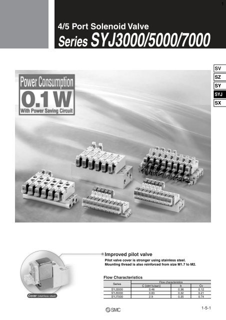
14/5 Port Solenoid Valve<strong>Series</strong> <strong>SYJ3000</strong>/<strong>5000</strong>/<strong>7000</strong>SVSZSYSYJSXImproved pilot valvePilot valve cover is stronger using stainless steel.Mounting thread is also reinforced from size M1.7 to M2.Cover (stainless steel)Flow Characteristics<strong>Series</strong><strong>SYJ3000</strong>SYJ<strong>5000</strong>SYJ<strong>7000</strong>Flow characteristicsC [(dm 3 /s·bar)] b Cv0.460.832.90.360.320.350.120.210.741-5-1
24/5 Port Solenoid ValveRubber Seal<strong>Series</strong> <strong>SYJ3000</strong>/<strong>5000</strong>/<strong>7000</strong>Variations<strong>Series</strong>Sonic conductanceC [dm 3 /(s . bar)]Type ofactuationVoltageElectrical entryOptionWith light/surgevoltage suppressorManualoverride<strong>SYJ3000</strong>For DCFor DCBody PortedSYJ<strong>5000</strong>SYJ<strong>7000</strong>P. 1-5-4P. 1-5-26Effective area0.9 mm 24/2 5/3{(A/B EA/EB) }0.474/2 5/3{ (A/B EA/EB) }2.44/2 5/3{ (A/B EA/EB) }2 position Single Double 24 VDC12 VDC6 VDC5 VDC3 VDCGrommet–+L plug connector–+M plug connector With surge voltagesuppressor With light/surgevoltage suppressorBase Mounted<strong>SYJ3000</strong>SYJ<strong>5000</strong>P. 1-5-50P. 1-5-4P. 1-5-260.464/2 5/3{ (A/B EA/EB) }0.834/2 5/3{ (A/B EA/EB) }3 position Closedcenter Exhaustcenter PressurecenterFor AC50 100 VAC / 60Hz50110 VAC / 60Hz50200 VAC / 60Hz50220 VAC / 60Hz+–DIN terminal(SYJ<strong>5000</strong>, <strong>7000</strong>only)For AC Note) With light/surgevoltage suppressor Non-lockingpush type Push-turnlockingslotted type Push-turnlocking levertypeSYJ<strong>7000</strong>M8 connector2.94/2 5/3{ (A/B EA/EB) }P. 1-5-50Note) All AC voltage models have built-in surge voltage suppressor.1-5-2
-+ -+PR<strong>Series</strong> <strong>SYJ3000</strong>/<strong>5000</strong>/<strong>7000</strong>3Manifold VariationsA, B port sizeManifold optionValve seriesA, B portlocationM3M51/8ø4With One-touch fittingApplicable tubing O.Dø6 ø8 N3 N7N9Individual IndividualSUP EXHspacer spacerassembly assemblyInterfaceregulatorFlat ribbon cable manifoldBody Ported<strong>SYJ3000</strong>SYJ<strong>5000</strong>SYJ<strong>7000</strong>Top:——————————————————————SVSZSY<strong>SYJ3000</strong>SideBottom——————————————————SYJSXBase MountedSYJ<strong>5000</strong>SYJ<strong>7000</strong>SideBottomSideBottom————————————————————————(P portregulation)(P portregulation)———Body portedA, B port-+ -+P portIndividual SUPspacer assemblyType 21PR P RR portPBase mountedA, B portP portR portIndividual EXHspacer assemblyR2Type 32P-+ -+A, B portPRR portP portR1Mixed mounting of 3 portvalves and 4, 5 port valves-+ -+RR portInterfaceregulator4, 5 port valve3 port valveA, B portABPP portAB-+ -+ ABA, B portBPRR portP portFor detailed specifications about<strong>SYJ3000</strong>, refer to page 1-5-17. ForSYJ<strong>5000</strong>, refer to page 1-5-41, andfor SYJ<strong>7000</strong>, refer to page 1-5-64.1-5-3
For details about certified productsconforming to international standards,visit us at www.smcworld.com.44/5 Port Solenoid ValveRubber Seal<strong>Series</strong> <strong>SYJ3000</strong>SpecificationsJIS Symbol5 port 4 port (manifold)2 position single(B)(A)2 43 1 5(R)(P)(R)2 position double(B)(A)2 43 1 5(R)(P)(R)3 position closed center(B)(A)2 43 1 5(R)(P)(R)3 position exhaust center(B)(A)2 43 1 5(R)(P)(R)2 position single(B)2 (A)41 3(P)(R)2 position double(B)2 (A)41(P)(R)33 position closed center(B)2 (A)41(P)(R)33 position exhaust center(B)2 (A)41(P)(R)33 position pressure center 3 position pressure center(B)(A)(B)2 42 (A)43 1 5(R)(P)(R)Body portedBase mounted1(P)(R)3Fluid2 position singleOperating pressure rangeMPa2 position double3 positionAmbient and fluid temperature (°C)Note 1)Response time (ms)2 position single, double(at 0.5 MPa)3 positionMax. operating2 position single, doublefrequency (Hz)3 positionManual override (Manual operation)Pilot exhaust methodLubricationMounting orientationShock/Vibration resistance (m/s 2 Note 2))EnclosureSolenoid SpecificationsElectrical entryCoil rated voltage (V)Allowable voltage fluctuationPower consumption (W)Apparent power VA ∗Bracket MountingDCAC 50 /60 HzDCStandardWith power saving circuit100 V110 V[115 V]AC200 V220 V[230 V]Air0.15 to 0.70.1 to 0.70.2 to 0.7–10 to 50 (No freezing. Refer to page 1-7-4.)15 or less30 or less103Non-locking push type, push-turn locking slotted type, push-turn locking lever typeIndividual exhaust for the pilot valve, common exhaust for the pilot and main valveNot requiredUnrestricted150/30Dustproof (∗ M8 connector conforms to IP65.)∗ Based on IEC529Note 1) Based on dynamic performance test, JIS B 8375-1981. (Coil temperature: 20°C, at rated voltage)Note 2) Impact resistance: No malfunction occurred when it is tested with a drop tester in the axialdirection and at the right angles to the main valve and armature in bothenergized and de-energized states every once for each condition.(Value in the initial state)Vibration resistance: No malfunction occurred in one sweep test between 45 and 2000 Hz. Testwas performed to axis and right angle directions of the main valve when pilotsignal is ON and OFF. (Value in the initial state)Grommet (G), (H), L plug connector (L),M plug connector (M), M8 connector (W)24, 12, 6, 5, 3100, 110, 200, 220±10% of rated voltage0.35 (With indicator light: 0.4)0.1 (With indicator light only)1.4 (With indicator light: 1.5)1.6 (With indicator light: 1.7)[1.7 (With indicator light: 1.8)]2.3 (With indicator light: 2.4)2.5 (With indicator light: 2.6)[2.7 (With indicator light: 2.8)]Surge voltage suppressorDiode (Non-polarity type: valistor)Indicator lightLED∗ In common between 110 VAC and 115 VAC, and between 220 VAC and 230 VAC.∗ For 115 VDC and 230 VDC, the allowable voltage is –15% to +5% of rated voltage.q Insert the lower hook of the mounting bracket intothe groove on the bottom of the valve as shown.w Press the valve and mounting bracket togetheruntil the upper hook of the bracket snaps intoplace in the groove on top of the valve.Made to Order Specifications(For details, refer to page 1-5-72.)1-5-4
<strong>Series</strong> <strong>SYJ3000</strong>65 port(Type 20 Manifold)Body portedType of actuation123452 position single solenoid2 position double solenoid3 position closed center3 position exhaust center3 position pressure centerRated voltageDC56VSR24 VDC12 VDC6 VDC5 VDC3 VDCNilSZRUHow to OrderLight/Surge voltage suppressorWithout light/surge voltage suppressorWith surge voltage suppresorWith light/surge voltage suppressorWith surge voltage suppressor (Non-polar type)With light/surge voltage suppressor (Non-polar type)∗ For AC voltage valves there is no “S” option.It is already built-in to the rectifier circuit.∗ For type “R” and “U”, DC voltage is onlyavailable.∗ Power saving circuit is only available in the“Z” type.AC ( 50 /60 Hz)1 100 VAC2 200 VAC3 110 VAC [115 VAC]4 220 VAC [230 VAC]∗ For type “W”, DC voltage is only available.SYJ3 1 2 0 5 M M3BracketNil: Without bracketF: With bracketSingle-+DoubleNote) • The double solenoid mountingbracket is supplied unattached.• To order the double solenoidbracket for use with a singlesolenoid valve, order the singlesolenoid valve without a bracketand order the bracket (VJ3000-13-1) separately.(Example) SYJ3120-5M-M3VJ3000-13-1Base mounted(4 port)Base mounted(5 port)SYJ3 2 3 0 5 MSYJ3 2 4 0 5 M(Manifold use only)4 portFor manifold type31, S31, 32, S325 portBody option0: Pilot valve individualexhaust for the pilotvalveCoil specificationsNil StandardWith power saving circuitT(24, 12 VDC only)∗ Power saving circuitis not available in thecase of “W” type.3: Common exhaust typefor main and pilot valveManual overrideNil: Non-locking push typeD: Push-turn locking slotted typePort sizeNil: Without sub-plate(With gasket and screws)M5: With M5 port sub-plateFor sub-plate,manifold type 41, S41, 46, S46R port P, E port R port P, E portElectrical entry24, 12, 6, 5, 3 VDC100,110, 200, 220 VACGrommet L plug connector M plug connectorG: Lead wirelength 300 mmL: With lead wire(Length 300 mm)M: With lead wire(Length 300 mm)MN: Withoutlead wire24, 12, 6, 5, 3 VDCM8 connectorWO: Withoutconnector cableE: Push-turn locking lever type+–+–– +–+H: Lead wirelength 600 mmLN: Withoutlead wireLO: WithoutconnectorMO: Withoutconnector1-5-6–+–+∗ “LN”, “MN” type: with 2 sockets.∗ For connector cable of M8 connector, refer to page 1-5-78.Note) When placing an order for body portedsolenoid valve as a single unit, mountingbolt for manifold and gasket are notattached. Order them separately, ifnecessary. (For details, refer to page 1-5-18 on catalog.)
4/5 Port Solenoid ValveRubber Seal<strong>Series</strong> <strong>SYJ3000</strong>7Construction(A)(B)2 position single4 22 position double(A)(B)4 2et(A)45 1 3(R)(P)(R)qrw(B)25 1 3(R)(P)(R)wq t r(A)4(B)2SV5(R)3 position closed center/exhaust center/pressure center3 position closed center(A)(B)4 25 1 3(R)(P)(R)3 position exhaust center(A)4 (B)21(P)3(R)uwtq(A)4(B)2r5(R)1(P)3(R)yuSZSYSYJSX5 1 3(R)(P)(R)3 position pressure center(A)4 (B)2Component PartsNo.qwertV11156VSR12345 1 3(R)(P)(R)DescriptionBodyPiston plateEnd coverPistonSpool valve assemblyMaterialZinc die-castedResinResinResinAlminum, HNBRHow to Order Pilot Valve AssemblyCoil specificationsNilATStandard: DC specificationsStandard: AC specificationsWith power saving circuit(24, 12 VDC only)∗ Power savingcircuit is notavailable in thecase of “W” type.Rated voltage24 VDC12 VDC6 VDC5 VDC3 VDC100 VAC 50/60 Hz200 VAC 50/60 Hz110 VAC 50/60 Hz[115 VAC 50/60 Hz]220 VAC 50/60 Hz[230 VAC 50/60 Hz]∗ For type “W”, DCvoltage is onlyavailable.5 GGHLLNLOMMNMOW0NoteWhiteWhiteWhiteLight/Surge voltage suppressorNil Without light/surge voltage suppressorS With surge voltage suppresorZ With light/surge voltage suppressorWith surge voltage suppressorR(Non-polar type)With light/surge voltage suppressorU(Non-polar type)∗ For AC voltage valves thereis no “S” option. It is alreadybuilt-in to the rectifier circuit.∗ For type “R” and “U”, DCvoltage is only available.∗ Power saving circuit is onlyavailable in the "Z" type.Electrical entryGrommet, 300 mm lead wireGrommet, 600 mm lead wireL plugconnectorM plugconnectorM8 connectorWith lead wireWithout lead wireWithout connectorWith lead wireWithout lead wireWithout connectorWithout connector cable∗ For connector cable of M8connector, refer to page 1-5-78.5(R)(This figure shows a closed center type.)Replacement PartsNo.yu1(P)Part no.<strong>SYJ3000</strong>-22-1V111 (T) -How to Order Connector Assebmlyfor L/M Plug ConnectorFor DC3(R)For 100 VACFor 200 VACDescriptionSub-platePilot valveFor othervoltages of ACWithout lead wire(with connector and2 of sockets only): SY100-30-4A-: SY100-30-1A-: SY100-30-2A-: SY100-30-ANil6101520253050Lead wire length300 mm600 mm1000 mm1500 mm2000 mm2500 mm3000 mm<strong>5000</strong> mmHow to Order M8 Connector Cable: SY100-30-3A-V100-49-1-12347uCable length300 mm500 mm1000 mm2000 mm<strong>5000</strong> mmNoteZinc die-casted1-5-7
2 Position SingleGGrommet (G), (H): SYJ3120- H -M3With bracket:GSYJ3120- -M3-FH13.254.4 [56.6]32.27.1G: Approx. 300H: Approx. 600(Lead wire length)2-ø3.5(For mounting)28.4223.28.24A B+1016.4-<strong>Series</strong> <strong>SYJ3000</strong>8[ ]: AC11.5M5 x 0.8(A, B port)7Manual override2-ø1.8(For manifold mounting)(Light/Surge voltage suppressor)19.334.7 [41.7]22.11513.5- +12.628 [35]54.4 [56.6]1110R P R(Bracket) 15277ø1.2(PE port)22.115M5 x 0.8(P, R port)L plug connector (L) :SYJ3120-L-M3 (-F)M plug connector (M):SYJ3120-M-M3 (-F)M8 connector (WO):SYJ3120-WO-M3 (-F)(2) 64.3 [66.5]Approx. 300(Lead wire length)28 [35]12.613.5Approx. 300(Lead wire length)(2) 54.5 [56.7]49.539.1 [46.1]13.5(2) 63.4M8 x 15632.51513.515151522.122.122.1Refer to page 1-5-79 for dimentionswith connector cable.1-5-8
4/5 Port Solenoid ValveRubber Seal<strong>Series</strong> <strong>SYJ3000</strong>92 Position Double[ ]: ACGGrommet (G), (H): SYJ3220- H-M3 (-F)78.8 [83.2]34.47.11.84G: Approx. 300H: Approx. 600(Lead wire length)SV8.2M3 x 0.5(A, B port)A B7Manual override2-ø1.8(For manifold mounting)SZSYSYJ2-ø3.2 equivalent(For mounting)(18.5)Bracket(Light/Surge voltage suppressor)SX22.1(18.5)1513.5- +100.512.628 [35](11.5)R P R14ø1.2(PE port)M5 x 0.8(P, R port)L plug connector (L):SYJ3220-L-M3 (-F)M plug connector (M):SYJ3220-M-M3 (-F)M8 connector (WO):SYJ3220-WO-M3 (-F)Approx. 300(Lead wire length)28 [35]12.6Approx. 300(Lead wire length)39.1 [46.1]M8 x 132.51513.513.513.598.6[103]79 [83.4]6996.8821522.11522.11522.1Refer to page 1-5-79 for dimentionswith connector cable.1-5-9
<strong>Series</strong> <strong>SYJ3000</strong>103 Position Closed Center/Exhaust Center/Pressure Center[ ]: ACGrommet (G), (H): SYJ3 420- H -M3 (-F)35G91.7 [96.1]40.2 [42.4]29.3 181.8 5.3G: Approx. 300H: Approx. 600(Lead wire length)8.2M3 x 0.5(A, B port)A B74Manual override2-ø1.8(For manifold mounting)2-ø3.2 equivalent(For mounting)(18.5)Bracket(Light/Surge voltage suppressor)22.1(18.5)0.51513.5- +(11.5)12.628 [35]R P R1410ø1.2(PE port)M3 x 0.5(P, R port)L plug connector (L):3SYJ3 4 20-L-M3 (-F)5M plug connector (M):3SYJ3 4 20-M-M3 (-F)5M8 connector (WO):3SYJ3 4 20-WO-M3 (-F)5Approx. 300(Lead wire length)28 [35]12.6Approx. 300(Lead wire length)39.1 [46.1]M8 x 132.515111.5 [115.9]50.1 [52.3]13.591.9 [96.3]40.3 [42.5]46.6 35.349.241.813.5 13.5109.753.11522.11522.11522.1Refer to page 1-5-79 for dimentionswith connector cable.1-5-10
R2R2PPR1R14/5 Port Solenoid ValveRubber Seal<strong>Series</strong> <strong>SYJ3000</strong>112 Position Single[ ]: ACGrommet (G), (H): SYJ3140- -M5GHM5 x 0.8(A, B port)10105(Light/Surge voltage suppressor)G: Approx. 300H: Approx. 600(Lead wire length)2-ø3.2(For mounting)Manual overrideB32.2B2254.4 [56.6]AA42.5111SVSZSYSYJSX- +1017.51326.141.5 [48.5]R2P10 10R11428528.535.6M5 x 0.8(P, R1, R2 port)L plug connector (L):SYJ3140-L-M5M plug connector (M):SYJ3140-M-M5M8 connector (WO):SYJ3140-WO-M541.5 [48.5]26.1Approx. 300(Lead wire length)52.6 [59.6]Approx. 300(Lead wire length)28.546M8 x 1142810 10R2P64.3 [66.5]142810 1049.554.5 [56.7]142810 105663.4R1528.535.6528.535.6528.535.6Refer to page 1-5-79 for dimentionswith connector cable.1-5-11
<strong>Series</strong> <strong>SYJ3000</strong>122 Position Double[ ]: ACGrommet (G), (H): SYJ3240- -M5GHM5 x 0.8(A, B port)101052-ø3.2(For mounting)Manual override222.5AB11BA(Light/Surge voltage suppressor)G: Approx. 300H: Approx. 600(Lead wire length)34.478.8 [83.2]- +1017.51326.141.5 [48.5]35.6R2PR110 1014285M5 x 0.8(P, R1, R2 port)L plug connector (L):SYJ3240-L-M5M plug connector (M):SYJ3240-M-M5M8 connector (WO):SYJ3240-WO-M541.5 [48.5]26.1Approx. 300(Lead wire length)52.6 [59.6] Approx. 300(Lead wire length)28.546M8 x 1142810 1098.6[103]14286979 [83.4]1428R2PR1R2PR1R2PR110 1010 108296.8555Refer to page 1-5-79 for dimentionswith connector cable.1-5-12
R2R2R2PPPR1R1R14/5 Port Solenoid ValveRubber Seal<strong>Series</strong> <strong>SYJ3000</strong>133 Position Closed Center/Exhaust Center/Pressure CenterGGrommet (G), (H): SYJ3 440- -M535H[ ]: AC10M5 x 0.8(A, B port)105SV2-ø3.2(For mounting)Manual override3222A B15.332.511SZSYSYJG: Approx. 300H: Approx. 600(Lead wire length)(Light/Surge voltage suppressor)BA37.5 [39.7]91.7 [96.1]SX- +1017.51326.141.5 [48.5]35.6R2PR110 1014285M5 x 0.8(P, R1, R2 port)L plug connector (L):3SYJ3 4 40-L-M55M plug connector (M):3SYJ3 4 40-M-M55M8 connector (WO):3SYJ3 4 40(R)-WO-M5541.5 [48.5]26.1Approx. 300(Lead wire length)52.6 [59.6]Approx. 300(Lead wire length)28.546M8 x 1281410 10547.4 [49.6]111.5 [115.9]281410 10532.6 49.337.6 [39.8]91.9 [96.3]281410 10555.8109.739.146.5Refer to page 1-5-79 for dimentionswith connector cable.1-5-13
14Manifold Standard<strong>Series</strong> <strong>SYJ3000</strong>Manifold SpecificationsManifold SpecificationsModelType 20Type 31, S31 Type 32, S32 Type 41, S41 Type 46, S46Manifold typeP (SUP), R (EXH)Valve stationsA, B portPorting specificationsPort sizeLocationDirectionP, R portA, B portValveTopM5 x 0.8M3 x 0.5Single base/B mountCommon SUP/Common EXH2 to 20 stationsBaseSideCommon SUPIndividual EXH1/8P: 1/8R: M5 x 0.8M5 x 0.8, C4 (One-touch fitting for ø4)Flow CharacteristicsBody portedfor internal pilotBase mountedfor internal pilotManifoldSS5YJ3-20Port size1(P), 5/3(R)port2(B), 4(A)portSYJ32 M5 x 0.8 M3 x 0.531SS5YJ3- S31 SYJ33 M5 x 0.8 M3 x 0.5 — —SS5YJ3-32-M5M5 x 0.8 0.25 0.19SS5YJ3-32-C4C4 0.25 0.18SYJ33 1/8SS5YJ3-S32-M5M5 x 0.8 0.25 0.26SS5YJ3-S32-C4C4 0.24 0.21SS5YJ3-41-M5M5 x 0.8 0.32 0.25SS5YJ3-41-C4C4 0.32 0.28SYJ34 1/8SS5YJ3-S41-M5M5 x 0.8 0.33 0.29SS5YJ3-S41-C4C4 0.32 0.27SS5YJ3-46-M5M5 x 0.8 0.20 0.25SS5YJ3-46-C41/8 C4 0.21 0.27SYJ34SS5YJ3-S46-M5M5 x 0.8 M5 x 0.8 0.20 0.25SS5YJ3-S46-C4C4 0.22 0.34Note) Value at manifold base mounted, 2 position single operatingFlow characteristics14/2 (PA/B) 4/25/3 (A/BR)C[dm 3 /(s·bar)]—b—Cv——0.0600.0590.0600.0570.0810.0790.0820.0790.0480.0500.0480.057C[dm 3 /(s·bar)]——0.320.300.290.270.330.350.340.340.100.210.190.10b—Cv—— —0.25 0.0770.27 0.0750.15 0.0620.18 0.0620.19 0.0790.24 0.0840.17 0.0810.24 0.0840.12 0.0240.13 0.0470.16 0.0240.090 0.024Effectivearea(mm 2 )0.90.9————————————How to Order Manifold (Example)Instruct by specifying the valves and blanking plate assembly to be mounted on the manifold alongwith the manifold base model no.Example: SS5YJ3-20-03 ··········· 1 set (Manifold base) SS5YJ3-S41-03-C4 ··· 1 set (Manifold base)∗ SYJ3120-5G-M3 ··· 2 sets (Valve)∗ SYJ3140-5LZ ··········· 2 sets (Valve)∗ <strong>SYJ3000</strong>-21-1A ···· 1 set (Blanking plate assembly) ∗ <strong>SYJ3000</strong>-21-2A ······· 1 set (Balnking plate assembly)The asterisk denotes the symbol for assembly. Prefix it to the part nos. of the solenoid valve, etc.∗ Use manifold specification sheet.1-5-14
4/5 Port Solenoid ValveRubber Seal<strong>Series</strong> <strong>SYJ3000</strong>15Flat Ribbon Cable Manifold Multiple valve wiring issimplified through the use ofthe flat cable connector. Clean appearanceIn the case of a flat ribbon cable type, eachvalve is wired on the print board of manifoldbase to allow the external wiring to be pipedall together with 26 pins MIL connector.Flat Ribbon Cable Manifold SpecificationsModelManifold typeP (SUP), R (EXH)Valve stationsA, B portPorting specificationsPort sizeLocationDirectionP, R portA, B portApplicable flat ribbon cableconnectorType 21PType 32PSingle base/B mountCommon SUP, Common EXH4 to 12 stationsValveBaseTopSide1/8M3 x 0.5 M5 x 0.8, C4 (One-touch fitting for ø4)Socket: 26 pins MIL type with strain relief(MIL-C-83503)Internal wiringIn common between +COM and –COM (Z type: +COM only)Rated voltage24, 12 VDC/100, 110 VACNote) The withstand voltage specification for the wiring unit section conforms to JIS C 0704, Grade 1 orits equivalent.SVSZSYSYJSXType 21PFlow CharacteristicsBody portedfor internal pilotBase mountedfor internal pilotManifoldSS5YJ3-21P SYJ323SS5YJ3-32P-M5SS5YJ3-32P-C4SYJ333Port size1(P), 5/3(R)port1/81/82(B), 4(A)portM3 x 0.5M5 x 0.8C4Note) Value at manifold base mounted, 2 position single operatingFlow characteristics14/2 (PA/B) 4/25/3 (A/BR)C[dm 3 /(s·bar)]–0.250.25bCv– –0.19 0.0600.18 0.059C[dm 3 /(s·bar)]–0.320.3bCv– –0.25 0.0770.27 0.075Effectivearea(mm 2 )0.9––How to Order Manifold SS5YJ3-32P-07-C4 ····· 1 pc. (Manifold base)∗ SYJ3133-5LOU ········· 3 pcs. (Valve)∗ SYJ3233-5LOU ········· 3 pcs. (Valve)∗ <strong>SYJ3000</strong>-21-4A ····· 1 pc. (Blanking plate assembly)∗ SY3000-37-28A ····· 3 pcs. (Connector assembly)∗ SY3000-37-29A ····· 3 pcs. (Connector assembly)The asterisk denotes the symbol for assembly. Prefix it to the part nos. of the solenoid valve, etc.How to Order Valves12345NilDEFor DC: SYJ3For AC: SYJ3Type of actuation2 position single2 position double3 position closed center3 position exhaust center3 position pressure center13Non-locking push typePush-turn locking slotted typePush-turn locking lever typeRated voltage561 2 331 2 33Rated voltage24 VDC12 VDC100 VAC110 VAC (AC115V)Manual override∗ Use manifold specification sheet.Light/Surge voltage suppressorZ With light/surge voltage suppressorWith light/surge voltage suppressorU(Non-polar type)Note) Z: Positive common specifications only.5 LO U1 LO ZA, B port sizeSymbolNilM3Port sizeBase mountedM3 x 0.5Note) In the case of flat cabletype, “U” type is for DCspecifications and “Z” typeis for AC specifications. Forthe opposite specification,please contact <strong>SMC</strong>.How to Order Connector Assembly12, 24 VDCSingle solenoidDouble solenoid,3 position type100 VACSingle solenoidDouble solenoid,3 position type110 VAC (115 VAC)Single solenoidDouble solenoid,3 position typeSY3000-37-28ASY3000-37-29ASY3000-37-46ASY3000-37-47ASY3000-37-54ASY3000-37-55A1-5-15
A<strong>Series</strong> <strong>SYJ3000</strong>16Common SUP/Common EXHType 20 (5 Port/Body ported)A, B portM3 x 0.5– +– +R portM5 x 0.8RR P P portM5 x 0.8Note) For more than 10 stations, supply air to both sides of P port and exhaust air from both sides of R port.How to OrderSS5YJ3–20– 05Number of stations02 2 stations: :20 20 stationsApplicable solenoid valveSYJ320--M3SYJ323--M3Applicable blanking plateassembly<strong>SYJ3000</strong>-21-1AType 31 (4 Port/Base mounted)Type 31Type S31 Single solenoid coil is on( )same side as the A, B port.How to OrderSS5YJ3– 31– 05 –M3A, B portM3 x 0.5R portM5 x 0.8P portM5 x 0.8A, B portM3 x 0.5Type 32 (4 Port/Base mounted)– +– +– +– +Type 32A, B portM5 x 0.8, C4ABABPP RRR port1/8P port1/8Type S32– + – + – + – + – +A, B portM5 x 0.8, C4P RSingle solenoid coil is on(same side as the A, B port.)– + – + – + – + – +BABAP RR portM5 x 0.8P portM5 x 0.8R port1/8P port1/8Valve mounting directionSingle solenoid coil is onNilopposite side as the A, B port.Single solenoid coil is onSsame side as the A, B port.How to OrderSS5YJ3–Valve mounting directionSingle solenoid coil is onNilopposite side as the A, B port.Single solenoid coil is onSsame side as the A, B port.32– 05 – M5M5C4N3Stations02 2 stations: :20 20 stationsStations02 2 stations: :20 20 stationsA, B port sizeM5 x 0.8One-touch fitting for ø4One-touch fitting for ø5/32"Applicable solenoid valveSYJ330-SYJ333-Applicable blanking plateassembly<strong>SYJ3000</strong>-21-2AP, R portthread typeNil RcF GN NPTT NPTFType 41 (5 Port/Base mounted)R port1/8A, B portM5 x 0.8, C4Type 41Common SUP/Individual EXH typeType 46 (5 Port/Base mounted)– +– +– +– +Type 46A, B portM5 x 0.8, C4ABABPPType S41Single solenoid coil is onsame side as the A, B port.( )P port1/8A, B portM5 x 0.8, C4Type S46Single solenoid coil is onsame side as the A, B port.P port1/8P port1/8R1 R2 portM5 x 0.8– + – + – + – + – +( )A, B portM5 x 0.8, C4BA– + – + – + – + – +R RBAPR port1/8How to OrderSS5YJ3–Valve mounting directionP port1/8Single solenoid coil is onNilopposite side as the A, B port.Single solenoid coil is onSsame side as the A, B port.How to OrderSS5YJ3–41– 05 – C4M5C4N3M5C4N3Stations02 2 stations: :20 20 stationsA, B port sizeM5 x 0.8One-touch fitting for ø4One-touch fitting for ø5/32"Note) For more than 10 stations, supply air to both sides of P port.R1 R2 portM5 x 0.8Valve mounting directionSingle solenoid coil is onNilopposite side as the A, B port.Single solenoid coil is onSsame side as the A, B port.46– 05 – M5Stations02 2 stations: :20 20 stationsA, B port sizeM5 x 0.8One-touch fitting for ø4One-touch fitting for ø5/32"Applicable solenoid valveSYJ340-SYJ343-Applicable blanking plateassembly<strong>SYJ3000</strong>-21-2AP, R portthread typeNil RcF GN NPTT NPTFApplicable solenoid valveSYJ340-SYJ343-Applicable blanking plateassembly<strong>SYJ3000</strong>-21-2AP portthread typeNil RcF GN NPTT NPTF1-5-16
<strong>Series</strong> <strong>SYJ3000</strong>18Combinations of Solenoid Valve, Manifold Gasket and Manifold Base5 port body ported0(Type SYJ32 3)A MarkApplicable manifold baseType SS5YJ3-20 ManifoldType SS5YJ3-21P base4 port base mounted0(Type SYJ33 3)Combination of Blanking Plate Assembly and Manifold BaseBlanking plate assembly<strong>SYJ3000</strong>-21-1AA MarkABlankingplate<strong>SYJ3000</strong>-21-1Blanking plate assembly<strong>SYJ3000</strong>-21-2ARound head combination screwSY100-33 -2(M1.7 x 7, matt nickel plated)<strong>SYJ3000</strong>-21-1Manifoldgasket<strong>SYJ3000</strong>-14 -2Applicable manifold baseType SS5YJ3-31Type SS5YJ3-S31 ManifoldType SS5YJ3-32 baseType SS5YJ3-S32Type SS5YJ3-32PSteel ball is driven in.5 port base mounted0(Type SYJ34 3)ManifoldA MarkManifoldManifoldgasketgasketgasket<strong>SYJ3000</strong>-14-7 <strong>SYJ3000</strong>-14-6 <strong>SYJ3000</strong>-14-2AManifoldgasket<strong>SYJ3000</strong>-14 -7ABlanking plateRound head combination screwSY100-33-3(M1.7 x 17, Matt nickel plated)Applicable manifold baseType SS5YJ3-41Type SS5YJ3-S41 ManifoldType SS5YJ3-46 baseType SS5YJ3-S460Difference between SYJ33 and SYJ34SYJ330, 333(4 port)3SYJ340, 343(5 port)03Applicable manifold baseType SS5YJ3-20 Manifold baseApplicable manifold baseSub-plateType SS5YJ3-41Type SS5YJ3-S41Type SS5YJ3-46Type SS5YJ3-S46Type SS5YJ3-31 Manifold baseType SS5YJ3-S31Type SS5YJ3-32Type SS5YJ3-S32Note) Manifold gasket “<strong>SYJ3000</strong>-14-2” can beused with the following manifold bases.Type SS5YJ3-31Manifold base ofTypeType-S31-32Type -S32Configuration of surface is different.Blanking plate assembly<strong>SYJ3000</strong>-21-4ABlanking plate assembly<strong>SYJ3000</strong>-21-3ARound head combination screwSY100-33-2(M1.7 x 7, matt nickel plated)Round head combination screwSY100-33-2(M1.7 x 7, matt nickel plated)Blanking plate<strong>SYJ3000</strong>-21-1Dust cap<strong>SYJ3000</strong>-42-1Blanking plateA Mark<strong>SYJ3000</strong>-21-1Manifoldgasket<strong>SYJ3000</strong>-14-6Dust cap<strong>SYJ3000</strong>-42-1A MarkManifoldgasket<strong>SYJ3000</strong>-14-7CautionMounting screw tightening torquesApplicable manifold baseType SS5YJ3-32PManifold baseApplicable manifold baseType SS5YJ3-21PManifold baseM1.7: 0.12 N·mUse caution to the assembly orientation forsolenoid valves, gasket, and optional parts.1-5-18
4/5 Port Solenoid ValveRubber Seal<strong>Series</strong> <strong>SYJ3000</strong>19Type 20 Manifold: Top Ported/SS5YJ3-20- Stations[ ]: ACGrommet (G)Approx. 300(Lead wire length)(Pitch)P = 10.5 12.591.7 [96.1]53.7 [55.9]Manual override31.5 15.8R P RABABABABAB4R P R7 1019.5 1.53.730.752.9 [55.1]2-ø3.5(For mounting)78.8 [83.2]511 101429M5 x 0.8(P, R port)SVSZSYSYJSXL2L13.5M3 x 0.5(A, B port)(Station n)(Light/Surge voltage suppressor)(Station 1)42 [49]26.613.5- + - + - + - + - +L plug connector (L)Approx. 300(Lead wire length)42 [49]26.6M plug connector (M)M8 connector (WO)Approx. 300(Lead wire length)53.1 [60.1]M8 x 1111.5 [115.9]0.898.6[103]62.8 [65]1.591.9 [96.3]79 [83.4]0.853 [55.2]1.561.9109.796.80.854.5 1.58294.9290.846.5Refer to page 1-5-79 for dimentionswith connector cable.Station nL1L2Station 235.528.534639456.549.556760677.570.578881898.591.5910910210119.5112.51113012312140.5133.51315114414161.5154.51517216516182.5175.51719318618203.5196.519214207Station 20224.5217.51-5-19
<strong>Series</strong> <strong>SYJ3000</strong>20Type 31 Manifold: Side Ported/SS5YJ3-31- Stations -M3[ ]: ACGrommet (G)91.7 [96.1] Approx. 30052.2 [54.4](Lead wire length)17.3 303.5RPBABAL1L2BABABAP R13.529.251.4 [53.6]78.8 [83.2]35.22-ø3.5(For mounting)7.57.5 12M5 x 0.8(P, R port)25Type S31 Manifold: Side PortedSS5YJ3-S31- Stations -M391.7 [96.1]Manual override52.2 [54.4]17.330RPABABABABABP R313.5Single solenoid coilis on same side asthe A,B port.255.229.251.4 [53.6]78.8 [83.2]12.5(Pitch)P = 10.5Manual override(Pitch)P = 10.5 9L2L13.52-ø3.5(For mounting)(Station 1)(Light/Surge voltage suppressor)(Station n)(Station n)(Light/Surge voltage suppressor)(Station 1)43.5 [50.5]28.1AB113.5- + - +(Pitch)P = 10.5AB31215M3 x 0.5(A, B port)15123M3 x 0.5(A, B port)BA- + - + - + - + - +(Pitch)P = 10.5BA114.5L plug connector (L)111.5 [115.9]98.6[103]0.861.3 [63.5]M plug connector (M)91.9 [96.3]79 [83.4] 0.851.5 [53.7]M8 connector (WO)M8 x 1109.796.8 0.860.44830.553820.894.9Approx. 300(Lead wire length)54.6 [61.6]Approx. 300(Lead wire length)2843.4 [47.3]Refer to page 1-5-79 for dimentionswith connector cable.Station nL1L2Station 235.528.534639456.549.556760677.570.578881898.591.5910910210119.5112.51113012312140.5133.51315114414161.5154.51517216516182.5175.51719318618203.5196.519214207Station 20224.5217.51-5-20
4/5 Port Solenoid ValveRubber Seal<strong>Series</strong> <strong>SYJ3000</strong>21Type 32 Manifold: Side Ported/SS5YJ3-32- Stations -M5,C4N3ForC4N3 (Built-in One-touch fitting)Grommet (G)For M591.7 [96.1] Approx. 30054.2 [56.4] (Lead wire length)3215.3(Station 1) (Station n)(Light/Surge voltage suppressor)48.5 [55.5]33.1415.5RPBA16.5 1BABA- + - +L1L2BABABAP R(Pitch)P = 10.5AB(Pitch)P = 10.55Manual override1 163.2 31.22-ø4.5(For mounting)152053.4 [55.6]78.8 [83.2]M5 x 0.8(A, B port)10 1/8(P, R port)31.57.5 174.515.5(Station 1)AB- + - +101736.512.5(4.4)(Station n)L1L2(Light/Surge voltage suppressor)A51520B[ ]: AC1.5 (Pitch) One-touch fitting16 P = 10.5(A, B port)Applicable tubing O.D.: ø4, ø5/32"SVSZSYSYJSXL plug connector (L)111.5 [115.9]98.6[103] 0.8(Lead wire length)Approx. 30033.148.4 [55.4]63.3 [65.5]M plug connector (M)0.891.9 [96.3]79 [83.4]Approx. 300(Lead wire length)59.6 [66.6]53.5 [55.7]M8 connector (WO)M8 x 1109.796.8 0.862.45335.50.81 558294.9Refer to page 1-5-79 for dimensionswith connector cable.Type S32 Manifold: Side PortedFor M591.7 [96.1]57.2 [59.4]2-ø4.5(For mounting)12.335(Light/Surge voltage suppressor)RPABL1L2Manual overrideAB(Pitch)P = 10.5(Station n)ABABAB- + - + - + - + - +15.5P R4Single solenoid coil is onsame side as the A,B port.31.534.215.5(Station 1)0.278.8 [83.2]56.4 [58.6]/SS5YJ3-S32- Stations -M5,C4N3ForC4 (Built-in One-touch fitting)N3101736.512.5(4.4)(Station n) (Station 1)L1L2 4.5(Light/Surge voltage suppressor)15.5-+- + - + - + - +20155M5 x 0.8(A, B port)BA(Pitch)P = 10.5BA117.5One-touch fitting(A, B port)Applicable tubing O.D.: ø4, ø5/32"BA(Pitch) 1.5P = 10.5 18BA51520SS5YJ3-32, S32- Stations -M5Station nL1L2SS5YJ3-32, S32- Stations -C4Station nL1L2Station 241.533.5Station 242.533.53524435344462.554.5463.554.55736557465683.575.5684.575.579486795868104.596.58105.596.59115107911610710125.5117.510126.5117.5111361281113712812146.5138.512147.5138.5131571491315814914167.5159.514168.5159.5151781701517917016188.5180.516189.5180.5171991911720019118209.5201.518210.5201.51922021219221212Station 20230.5222.5Station 20231.5222.51-5-21
RRP<strong>Series</strong> <strong>SYJ3000</strong>22Type 41 Manifold: Side Ported/SS5YJ3-41- Stations -M5,C4N3Grommet (G)For M511.5 18101/8(R port)91.7 [96.1] Approx. 30061.7 [63.9] (Lead wire length)7.8 39.532-ø4.5(For mounting)416(Pitch)P = 10.5L2L1(Station 1)(Light/Surge voltage suppressor)48.5 [55.5]33.1ABBA217BA- + - +BABABAP(Pitch)P = 10.5Manual override4.338.7(Station n)AB5152060.9 [63.1]78.8 [83.2]M5 x 0.8(A, B port)101/8(P port)36.521.5For C4N3 (Built-in One-touch fitting)(Station 1)(Light/Surge voltage suppressor)20155AB- + - +1036.421.41/8(P port)(4.4)(Station n)AB[ ]: AC217(Pitch)P = 10.5One-touch fitting(A, B port)Applicable tubing O.D.: ø4, ø5/32"L plug connector (L)111.5 [115.9]98.6[103] 0.870.8 [73]M plug connector (M)91.9 [96.3]79 [83.4] 0.861 [63.2]M8 connector (WO)M8 x 1109.796.8 0.869.95335.50.862.58294.9(Lead wire length)Approx. 30033.148.5 [55.5]Approx. 300(Lead wire length)59.6 [66.6]Refer to page 1-5-79 for dimensionswith connector cable.Type S41 Manifold: Side PortedFor M5Manual override(Pitch)P = 10.5 16Single solenoid coil is onsame side as the A,B port.C4/SS5YJ3-S41- Stations -M5, N3For C4N3 (Built-in One-touch fitting)91.7 [96.1]55.2 [57.4]14.333(Station n)(Light/Surge voltage suppressor)ABABABABAR R2.2L2 4L1B(Station 1)32.233.536.578.8 [83.2]54.4 [56.6]2-ø4.5(For mounting)(Light/Surge voltage suppressor) (Station n)1036.421.4(4.4)(Station 1)1/8(P port)-+-+-+-+- +-+-+-+-+- +20155M5 x 0.8(A, B port)BABA(Pitch) 2P = 10.5 1520155One-touch fitting(A, B port)Applicable tubing O.D.: ø4, ø5/32"BA(Pitch)P = 10.5BA215Station nL1L2Station 239.531.535042460.552.557163681.573.5792848102.594.5911310510123.5115.51113412612144.5136.51315514714165.5157.51517616816186.5178.51719718918207.5199.519218210Station 20228.5220.51-5-22
4/5 Port Solenoid ValveRubber Seal<strong>Series</strong> <strong>SYJ3000</strong>23Type 46 Manifold: Side Ported/SS5YJ3-46- Stations -M5,C4N3Grommet (G)For M5Approx. 300(Lead wire length)91.7 [96.1]60.7 [62.9]38.58.81014.5(Station 1)(Light/Surge voltage suppressor)48.5 [55.5]33.14PAB1.511.8BA-+BA-+(Pitch)P = 10.5BAL2L1BABA(Pitch)P = 10.5PManual override3.337.7(Station n)AB59.9 [62.1]78.8 [83.2]2-ø4.5(For mounting)51520M5 x 0.8(A, B port)1019351/8(P port)ForC4N3 (Built-in One-touch fitting)-+-+1018.934.91/8(P port)(4.4)(Station 1) (Station n)(Light/Surge voltage suppressor)2015511.8ABAB[ ]: AC1.5 (Pitch) One-touch fittingP = 10.5(A, B port)Applicable tubing O.D.: ø4, ø5/32"SVSZSYSYJSXL plug connector (L)0.8M plug connector (M)0.8M8 connector (WO)M8 x 10.85335.5111.5 [115.9]98.6[103]69.8 [72]79 [83.4]91.9 [96.3]60 [62.2]96.8109.768.98294.961.50.8(Lead wire length)Approx. 3003348.5 [55.5]Approx. 300(Lead wire length)59.6 [66.6]Type S46 Manifold: Side PortedFor M5Manual override(Pitch)P = 10.5 14.5Single solenoid coil is onsame side as the A,B port.C4/SS5YJ3-S46- Stations -M5,N3ForRefer to page 1-5-79 for dimensionswith connector cable.C4N3 (Built-in One-touch fitting)91.9 [96.3]54.7 [56.9]32.5 14.825PABABABABABP0.52.7L2 4L1(Station n) (Station 1)2531.73553.9 [56.1]78.8 [83.2]2-ø4.5(For mounting)18.934.9(4.4)(Light/Surge voltage suppressor) (Station n) (Station 1)101/8(P port)(Light/Surge voltage suppressor)-+-+-+-+-+-+-+-+-+-+20155M5 x 0.8(A, B port)BA(Pitch)P = 10.5BA1.515.720155BAOne-touch fitting(Pitch)(A, B port)P = 10.5Applicable tubing O.D.: ø4, ø5/32"BA1.515.7Station nL1L2Station 239.531.535042460.552.557163681.573.5792848102.594.5911310510123.5115.51113412612144.5136.51315514714165.5157.51517616816186.5178.51719718918207.5199.519218210Station 20228.5220.51-5-23
AAAAAABBBBBB-+-+-+-+-+-+-+-+<strong>Series</strong> <strong>SYJ3000</strong>24Flat Ribbon Cable Manifold[ ]: ACSS5YJ3-21P- Stations -00Manual overrideL1L24M3 x 0.5(A, B port)111.5 [115.9]62.1 [64.3]30 17.37 8.52-ø4.5(For mounting)PR(Pitch)P = 12.52 218.5(Station n) (Station 1)(Light/Surge voltage suppressor)-+-+-+-+-+-+R P35.21629.245.598.6[103]61.3 [63.5]Triangle mark1017 7.531.51/8(P, R port)65.348.5 [55.5]2028.55.825.6Applicable connector: 26 pins MIL typeWith strain relief(Conforming to MIL-C-83503)SS5YJ3-32P- Stations -M5,C4 ForC4N3N3 (Built-in One-touch fitting)For M5(Pitch)M5 x 0.8(A, B port)BAP = 12.5 19.51BA515One-touch fitting(A, B port)Applicable tubing O.D.: ø4, ø5/32"(Pitch)P = 12.5 19.5151520AABBManual overrideL1L241010111.5 [115.9]64.1 [66.3]15.33216(Station n) (Station 1)(Light/Surge voltage suppressor)Applicable connector: 26 pins MIL typeWith strain relief(Conforming to MIL-C-83503)48.5 [55.5]20PR2-ø4.5(For mounting)A-B+A-B+A-B+A-B+A-B+A-BR P(Pitch)P = 12.5 18.5+13.231.263.3 [65.5]5.825.698.6[103]Triangle mark17 7.531.51/8(P, R port)65.312.5(4.4)1736.51/8(P, R port)50.570.31-5-2428.5Station nL1L2Station 472.564.558577697.589.571101028122.5114.5913512710147.5139.511160152Station 12172.5164.5
1-5-2525
For details about certified productsconforming to international standards,visit us at www.smcworld.com.265 Port Solenoid ValveRubber Seal<strong>Series</strong> SYJ<strong>5000</strong>SpecificationsJIS SymbolBody ported2 position single(A)(B)4 25 1 3(R1)(P)(R2)2 position double(A)(B)4 25 1 3(R1)(P)(R2)3 position closed center(A)(B)4 25 1 3(R1)(P)(R2)3 position exhaust center(A)(B)4 25 1 3(R1)(P)(R2)3 position pressure center1-5-26(A)(B)4 25 1 3(R1)(P)(R2)Body portedBase mountedBase mounted (with sub-plate)2 position single(B)(A)2 43 1(R)(P)2 position double(B)(A)2 43 1(R)(P)3 position closed center(B)(A)2 43 1(R)(P)3 position exhaust center(B)(A)2 43 1(R)(P)3 position pressure center(B)(A)2 43 1(R)(P)Made to Order Specifications(For details, refer to pages 1-5-72 to 73.)Fluid2 position singleOperating pressure rangeMPa2 position double3 positionAmbient and fluid temperature (°C)Response time (ms)(at 0.5 MPa)Max. operating frequency(Hz)Note 1)Manual override (Manual operation)Pilot exhaust methodLubricationMounting orientationShock/Vibration resistance (m/s 2 )EnclosureNote 2)Solenoid SpecificationsElectrical entryCoil rated voltage (V)Allowable voltage fluctuationPower consumption (W)Apparent power VA ∗Surge voltage suppressorIndicator light2 position single, double3 position2 position single, double3 positionBuilt-in Speed ControllerSYJ55StandardWith power saving circuit100V110V[115V]200V220V[230V] Built-in exhaust flow controls enable simple cylinderspeed adjustments. When mounted on the manifold, the common exhaustdischarges the pilot and main valve exhaust through acommon EXH port to enable simple exhausting.(B)JIS Symbol2 (A)4(Single)How to order valve with built-in speed controllerSYJ5 5 – –Type ofactuationBody optionRated voltageLead wire3(R)(P)1DCAC 50/60 HzDCACPort sizeManual overrideLight/Surge voltage suppressorAir0.15 to 0.70.1 to 0.70.15 to 0.7–10 to 50 (No freezing. Refer to page 1-7-4.)25 or less40 or less53Non-locking push type, push-turn locking slotted type, push-turn locking lever typeIndividual exhaust for the pilot valve, common exhaust for the pilot and main valveNot requiredUnrestricted150/30Dustproof (∗ DIN terminal, M8 connector conforms to IP65.)∗ Based on IEC529Note 1) Based on dynamic performance test, JIS B 8375-1981. (Coil temperature: 20°C, at rated voltage, without surge suppressor)Note 2) Impact resistance: No malfunction occurred when it is tested with a drop tester in the axial direction and at the right angles tothe main valve and armature in both energized and de-energized states every once for each condition.(Value in the initial state)Vibration resistance: No malfunction occurred in one sweep test between 45 and 2000 Hz. Test was performed to axis and rightangle directions of the main valve and armature when pilot signal is ON and OFF. (Value in the initial state)Grommet (G), (H), L plug connector (L)M plug connector: (M), DIN terminal (D)M8 connector (W)24, 12, 6, 5, 3100, 110, 200, 220±10% of rated voltage0.35 {With light: 0.4 (DIN terminal with indicator light: 0.45)}0.1 (With indicator light only)1.4 (With indicator light: 1.5)1.6 (With indicator light: 1.7)[1.7 (With indicator light: 1.8)]2.3 (With indicator light: 2.4)2.5 (With indicator light: 2.6)[2.7 (With indicator light: 2.8)]Diode (DIN terminal, varistor when non-polar types)LED (Neon light when AC with DIN terminal)∗ In common between 110 VAC and 115 VAC, and between 220 VAC and 230 VAC.∗ For 115 VAC and 230 VAC, the allowable voltage is –15% to +5% of rated voltage.AThrottle Valve Characteristics ( R)Effective area (mm 2 )210(Fully 1 2 3 4 5 6 7 (Fullyclosed)open) When using SYJ553 model the speed controllermust be opend more than 1 complete rotation fromfully closed in order to function proerly. Adjust the speed controller with a torque of 0.3 N mor less.Plate fixing screwNote) Do not loosen plate fixing screw.B
5 Port Solenoid ValveRubber Seal<strong>Series</strong> SYJ<strong>5000</strong>27Flow Characteristics/WeightBody portedBase mountedValve modelSYJ520--M53 positionSYJ520--C43 positionSYJ520--C63 positionSYJ540--013 positionType of actuation2 position2 position2 position2 positionSingleDoubleClosed centerExhaust centerPressure centerSingleDoubleClosed centerExhaust centerPressure centerSingleDoubleClosed centerExhaust centerPressure centerSingleDoubleClosed centerExhaust centerPressure centerPort sizeNote 1)Flow characteristics1, 5, 3 4, 2 14/2 (PA/B) 4/25/3 (A/BEA/EB)(P, EA, EB) (A, B) C [dm 3 /(s·bar)]0.47b0.41Cv0.13C [dm 3 /(s·bar)]0.47b0.41Cv0.13M5 x 0.8 M5 x 0.8 0.49 0.44 0.13 0.44 0.40 0.120.46 0.37 0.12 0.47 [0.39] 0.43 [0.35] 0.13 [0.10]0.49 [0.39] 0.51 [0.38] 0.14 [0.10] 0.45 0.42 0.120.69C4M5 x 0.8 (One-touch 0.69fitting for ø4) 0.560.57 [0.41]0.390.400.400.4 [0.37]0.180.190.150.15 [0.10]C6M5 x 0.8 (One-touchfitting for ø6)0.700.720.670.360.370.540.190.190.190.82 [0.44] 0.41 [0.39] 0.23 [0.12]1/81/80.790.800.710.210.280.260.190.180.180.99 [0.47] 0.29 [0.38] 0.24 [0.12]0.440.430.41 [0.41]0.410.470.440.41 [0.41]0.410.830.861.1 [0.60]0.720.390.400.37 [0.37]0.370.400.340.38 [0.38]0.360.320.340.24 [0.44]0.380.120.120.10 [0.11]0.100.120.120.11 [0.11]0.110.210.200.26 [0.18]0.18Grommet46647553718253718280 (49)98 (64)109 (75)L/M plugconnector47667754738454738481 (47)100 (66)111 (77)Note 2, 3)Weight (g)DINterminal681081197511512675115126102 (68)142 (108)153 (119)Note 1) [ ]: Denotes normal position. Exhaust center: 4/2 5/3, Pressure center: 1 4/2Note 2) ( ): Without sub-plate.Note 3) For DC voltages. For AC voltages add 3 g to the weight of the single solenoid and 6 g to the weight of the double solenoid and 3 position types.M8connector517485588172588192517485SVSZSYSYJSXCylinder Speed ChartBody ported<strong>Series</strong>SYJ5120-M5Averagespeed(mm/s)8007006005004003002001000Use as a guide for selection.Please confirm the actual conditions with <strong>SMC</strong>Sizing Program.Bore size<strong>Series</strong> CJ2Pressure 0.5 MPaLoad rate: 50%Stroke 60 mm<strong>Series</strong> CM2Pressure 0.5 MPaLoad rate: 50%Stroke 300 mmø6 ø10 ø16 ø20 ø25 ø32 ø40Perpendicular, upward actuationHorizontal actuationBase mounted<strong>Series</strong>SYJ5140-01Averagespeed(mm/s)<strong>Series</strong> CJ2Pressure 0.5 MPaLoad rate: 50%Stroke 60 mmBore size<strong>Series</strong> CM2Pressure 0.5 MPaLoad rate: 50%Stroke 300 mm<strong>Series</strong> MB/CA2Pressure 0.5 MPaLoad rate: 50%Stroke 500 mmø6 ø10 ø16 ø20 ø25 ø32 ø40 ø40 ø50 ø63 ø80 ø1008007006005004003002001000∗ Cylinder is in extending. Speed controller is meter-out, which is directly connected with cylinder and its needle is fully opened.∗ Average speed of cylinder is obtained by dividing the full stroke time by the stroke.∗ Load factor: ( (Load weight x 9.8)/Theoretical force) x 100%Perpendicular, upward actuationHorizontal actuationConditionsSYJ5120-M5Body portedTubing bore x LengthSpeed controllerSilencer<strong>Series</strong> CJ2 <strong>Series</strong> CM2 <strong>Series</strong> MB/CA2ø4 x 1 m ø6 x 1 m ø8 x 1 mAS1301F-04 AS3301F-06 AS3301F-08AN120-M5 AN110-01Base mountedTubing bore x LengthSYJ5140-01 Speed controllerSilencer<strong>Series</strong> CJ2 <strong>Series</strong> CM2 <strong>Series</strong> MB/CA2ø4 x 1 m ø6 x 1 mAS2301F-04 AS3001F-06AN101-01 AN101-011-5-27
–+–+<strong>Series</strong> SYJ<strong>5000</strong>2812345Type of actuation2 position single solenoid2 position double solenoid3 position closed center3 position exhaust center3 position pressure center(For manifold type 20)Rated voltageDC56VSRNilSZRU24 VDC12 VDC6 VDC5 VDC3 VDCHow to OrderLight/Surge voltage suppressorElectrical entry for G, H, L, M, W∗ DC specifications of type “D”and “DO” is only availablewith 12 and 24 VDC.Without light/surge voltage suppressorWith surge voltage suppresorWith light/surge voltage suppressorWith surge voltage suppressor (Non-polar type)With light/surge voltage suppressor (Non-polar type)∗ For AC voltage valves there is no “S” option.It is already built-in to the rectifier circuit.∗ For type “R” and “U”, DC voltage is only available.∗ Power saving circuit is only available in the "Z" type.AC ( 50 /60 Hz)1 100 VAC2 200 VAC3 110 VAC [115 VAC]4 220 VAC [230 VAC]∗ For type “W”,DC voltage isonly available.A, B port sizeM5C4C6N3N7Electrical entry for DNil Without light/surge voltage suppressorS With surge voltage suppressor (Non-polar type)Z With light/surge voltage suppressor (Non-polar type)∗ “DOZ” is not available.∗ For AC voltage valves there is no “S” option.It is already built-in to the rectifier circuit.BracketM5 x 0.8One-touch fitting for ø4One-touch fitting for ø6One-touch fitting for ø5/32"One-touch fitting for ø1/4"Nil: Without bracketF: With bracketNote) The mounting bracket issupplied unattached.Body ported SYJ5 1 2 0 5 LM5Base mountedSYJ5 2 4 0 5LFor sub-plate, manifold type40, 41, 42, 43Body option0: Pilot valve individualexhaust for the pilot valveR portP, E port3: Common exhaust typefor main and pilot valveCoil specificationsNil StandardWith power saving circuitT∗ Power saving circuit isnot available in thecase of “D”, “DO” or“W” type.Manual overrideNil: Non-locking pushtypeThread typeNil RcF GN NPTT NPTFPort sizeNil: Without sub-plateD: Push-turn lockingslotted typeR portP, E portElectrical entry24, 12, 6, 5, 3 VDC100,110, 200, 220 VAC24,12 VDC100,110, 200, 220 VACGrommet L plug connector M plug connector DIN terminalG: Lead wire L: With lead wire M: With lead wire MN: Withoutlength 300 mm (Length 300 mm) (Length 300 mm) lead wire24, 12,6, 5, 3 VDCM8 connectorD: With connector WO: WithoutconnectorcableE: Push-turn lockinglever type(With gasket and screws)01: 1/8 With sub-plate–+–+H: Lead wirelength 600 mmLN: Withoutlead wireLO: WithoutconnectorMO: WithoutconnectorDO: Withoutconnector–+–+1-5-28∗ LN, MN type: with 2 sockets.∗ DIN terminal “Type Y” conforming to DIN43650C standard is also available.(For details, refer to catalog in page 1-5-73.)∗ For connector cable of M8 connector, refer to page 1-5-78.
5 Port Solenoid ValveRubber Seal<strong>Series</strong> SYJ<strong>5000</strong>29Construction2 position single (A) (B)2 position double42(A)4(B)25(R1)(A)41(P)5 1 3(R1) (P) (R2)(B)23(R2)5(R1)(A)41(P)(B)25 1 3(R1) (P) (R2)e qy trwwq t ri3(R2)uiSVSZSYSYJSX3 position closed center/exhaust center/pressure center3 position closed center(A) (B)4 25 1 3(R1) (P)(R2)3 position exhaust center(A)4 (B)2tq(A)4(B)2rw5 1 3(R1) (P)(R2)3 position pressure center(A)4 (B)2i5 1 3(R1) (P)(R2)5(R1)1(P)3(R2)(This figure shows a closed center type.)Component PartsNo.qwertyDescriptionMaterialBodyAluminum die-castedPiston plateResinEnd coverResinPistonResinSpool valve assembly Aluminum, H-NBRSpool springStainless steelNoteWhiteWhiteWhite———Replacement PartsNo.uiDescriptionSub-platePilot valvePart no.SYJ<strong>5000</strong>-22-1V111(T)-NoteAluminum die-casted1-5-29
<strong>Series</strong> SYJ<strong>5000</strong>How to Order Pilot Valve AssemblyV111Coil specificationsNil Standard: DC specificationsA Standard: AC specificationsWith power saving circuitT(24, 12 VDC only)∗ Power saving circuit is notavailable in the case of “W” type.56VSR1234Rated voltage24 VDC12 VDC6 VDC5 VDC3 VDC100 VAC 50/60 Hz200 VAC 50/60 Hz110 VAC 50/60 Hz[115 VAC 50/60 Hz]220 VAC 50/60 Hz[230 VAC 50/60 Hz]∗ For type “W”, DCvoltage is onlyavailable.5 GLight/Surge voltage suppressorNil Without light/surge voltage suppressorS With surge voltage suppresorZ With light/surge voltage suppressorR With surge voltage suppressor (Non-polar type)U With light/surge voltage suppressor (Non-polar type)∗ For AC voltage valves thereis no “S” option. It is alreadybuilt-in to the rectifier circuit.∗ For type “R” and “U”, DCvoltage is only available.∗ Power saving circuit is onlyavailable in the "Z" type.Electrical entryG Grommet, 300 mm lead wireH Grommet, 600 mm lead wireLWith lead wireL plugLNWithout lead wireconnectorLOWithout connectorMWith lead wireM plugMNWithout lead wireconnectorMOWithout connectorW0 M8 connector Without connector cable∗ For connector cable of M8connector, refer to page 1-5-78.How to Order Connector Assemblyfor L/M Plug ConnectorFor DCFor 100 VACFor 200 VACFor othervoltages of AC: SY100-30-4A-: SY100-30-1A-: SY100-30-2A-: SY100-30-AWithout lead wire(with connector and 2 of sockets only)Lead wire lengthNil 300 mm6 600 mm10 1000 mm15 1500 mm20 2000 mm25 2500 mm30 3000 mm50 <strong>5000</strong> mmHow to Order M8 Connector Cable: SY100-30-3A-V100-49-1-30V1155 24 VDC6 12 VDC1 100 VAC 50/60 Hz5 D2 200 VAC 50/60 Hz110 VAC 50/60 Hz3[115 VAC 50/60 Hz]4Rated voltage220 VAC 50/60 Hz[230 VAC 50/60 Hz]∗ DC specifications oftype “D” and “DO” isonly available with12 and 24 VDC.∗ Power saving circuitis not available inthe case of “D” or“DO” type.Light/Surge voltage suppressorNilSZWithout light/surge voltage suppressorWith surge voltage suppressor (Non-polar type)With light/surge voltage suppressor (Non-polar type)∗ “DOZ” is not available.∗ For AC voltage valves there is no “S” option.It is already built-in to the rectifier circuit.Electrical entryD DIN With connectorDO terminal Without connectorNote) Do not replace SV111 (G, H, L, M,W) to SV115 (DIN terminal) andvice versa when replacing pilotvalve assembly only.Cable length1 300 mm2 500 mm3 1000 mm4 2000 mm7 <strong>5000</strong> mm1-5-30
2 Position SingleGGrommet (G), (H): SYJ5120- -M5H63.1 [65.3]4119.5G: Approx. 300H: Approx. 600(Lead wire length)With bracketGSYJ5120- -M5-F2-ø3.5(For mounting)3730 3.5+182510.61152-M3 x 0.5(Mounting screw)2.5 18M5 x 0.8(A, B port)23203.5A4101911B3Manual override2-ø2.6(For manifold mounting)(Light/Surge voltage suppressor)2-ø2.6(For mounting)-+12.728.1 [35.1](Bracket)Built-in One-touch fitting:G C4, N3SYJ5120- - (-F)19.5HC6, N73.5-5 Port Solenoid ValveRubber Seal<strong>Series</strong> SYJ<strong>5000</strong>31[ ]: ACH19.735.1 [42.1]63.1 [65.3]2.3SVSZSYSYJSXAB16M5 x 0.8(P, R1, R2 port)R1P21R215ø1.4(PE port)32.3 (3.2)10.6One-touch fitting(A, B port)Applicable tubing O.D.: ø4, ø5/32": ø6, ø1/4"(2.3)L plug connector (L):SYJ5120-L-M5(-F)M plug connector (M):SYJ5120-M-M5(-F)DIN terminal (D):SYJ5120-D-M5(-F)M8 connector (WO):SYJ5120-WO-M5(-F)Approx. 300(Lead wire length)73 [75.2](2.3)202328.1 [35.1]12.731119.5Approx. 300(Lead wire length)2-ø2.6(For mounting)63.2 [65.4]58.2(2.3)39.2 [46.2]202331119.582.1 Max. 10Pg72-ø2.6(For mounting)Applicable cable O.D.ø3.5 to ø742.2(2.3)60.953.442.120232731119.5832-ø2.6(For mounting)M8 x 172.164.7(2.3)32.615.1202331119.52-ø2.6(For mounting)Refer to page 1-5-79 for dimentionswith connector cable.1-5-31
<strong>Series</strong> SYJ<strong>5000</strong>322 Position Double[ ]: ACGrommet (G), (H): SYJ5220- -M5GHBuilt-in One-touch fitting:G C4, N3SYJ5220- -HC6, N787.2 [91.6]43511G: Approx. 300H: Approx. 600(Lead wire length)3.5ABABM5 x 0.8(A, B port)1019Manual override2-ø2.6(For manifold mounting)10.6(Light/Surge voltage suppressor)2023-+(3.2)32.3One-touch fitting(A, B port)Applicable tubing O.D.: ø4, ø5/32": ø6, ø1/4"3112-ø2.6(For mounting)12.728.1 [35.1]M5 x 0.8(P, R1, R2 port)R1 P21R215ø1.4(PE port)L plug connector (L):SYJ5220-L-M5M plug connector (M):SYJ5220-M-M5DIN terminal (D):SYJ5220-D-M5M8 connector (WO):SYJ5220-WO-M5Approx. 300(Lead wire length)28.1 [35.1]12.7Approx. 300(Lead wire length)39.2 [46.2]Pg7Max. 10Applicable cable O.D.ø3.5 to ø760.953.442.1M8 x 132.615.1107 [111.4]203112-ø2.6(For mounting)87.4 [91.8]77.4203112-ø2.6(For mounting)125.245.42023311127105.290.4203112-ø2.6(For mounting)2323272-ø2.6(For mounting)23Refer to page 1-5-79 for dimentionswith connector cable.1-5-32
5 Port Solenoid ValveRubber Seal<strong>Series</strong> SYJ<strong>5000</strong>333 Position Closed Center/Exhaust Center/Pressure Center[ ]: ACGrommet (G), (H): SYJ54 G20- H -M535103.2 [107.6]44.2 [46.4]36.9 22.15M5 x 0.8(A, B port)A101911BManual overrideG: Approx. 300H: Approx. 600(Lead wire length)2-ø2.6(For manifold mounting)(Light/Surge voltage suppressor)2023-+Built-in One-touch fitting:C4, N3SYJ5 20- -(3.2)32.33453.5GHA10.6C6, N744.2 [46.4]BOne-touch fitting(A, B port)Applicable tubing O.D.: ø4, ø5/32": ø6, ø1/4"SVSZSYSYJSX3112-ø2.6(For mounting)12.728.1 [35.1]M5 x 0.8(P, R1, R2 port)R1P21R215ø1.4(PE port)L plug connector (L):3SYJ5 4 20-L-M55M plug connector (M):3SYJ5 4 20-M-M55DIN terminal (D):3SYJ5 4 20-D-M55M8 connector (WO):3SYJ5 4 20-WO-M55Approx. 300(Lead wire length)123 [127.4]54.1 [56.3]202328.1 [35.1]12.73112-ø2.6(For mounting)Approx. 300(Lead wire length)103.4 [107.8]44.3 [46.5]54.1 39.339.2 [46.2]20233112-ø2.6(For mounting)Max. 10Pg7141.263.2Applicable cable O.D.ø3.5 to ø760.953.442.138.1 23.3202331164.11432-ø2.6(For mounting)121.2M8 x 1 32.615.153.245.860.620233112-ø2.6(For mounting)27Refer to page 1-5-79 for dimentionswith connector cable.1-5-33
B<strong>Series</strong> SYJ<strong>5000</strong>342 Position Single[ ]: ACGrommet (G), (H): SYJ5140- -01GHBuilt-in speed controller:GSYJ5150- -01H1/8(A, B port)1711.519.4 10.38.5Max. 13.52-ø4.3(For mounting)Manual override37.5A B4With interface regulatorA24(Light/Surge voltage suppressor)G: Approx. 300H: Approx. 600(Lead wire length)R P41 0.563.6 [65.8]107.5 [109.7]50.1 [57.1]4534.7- +15243221.561/8(P, R port)17 1745.568.569.6 [76.6]54.243.931.5L plug connector (L):SYJ5140-L-01M plug connector (M):SYJ5140-M-01DIN terminal (D):SYJ5140-D-01M8 connector (WO):SYJ5140-WO-0145.5171750.1 [57.1]34.760.5Approx. 300(Lead wire length)73.5 [75.7]45.51717661.2 [68.2]Approx. 300(Lead wire length)0.558.763.7 [65.9]83.5Applicable cable O.D.ø3.5 to ø782.975.464.14945.51717642.782.6 Max. 10Pg745.51717654.637.10.5M8 x 165.272.668.521.568.521.568.521.50.58.5621.5Refer to page 1-5-79 for dimentionswith connector cable.1-5-34
5 Port Solenoid ValveRubber Seal<strong>Series</strong> SYJ<strong>5000</strong>352 Position Double[ ]: ACGGrommet (G), (H): SYJ5240- -01HBuilt-in speed controller:GSYJ5250- -01H1/8(A, B port)17 11.58.5Max. 13.519.4 10.3SV2-ø4.3(For mounting)Manual override37.5 4BA BA24SZSYSYJG: Approx. 300H: Approx. 600(Lead wire length)R P41.5 1.587.2 [91.6]23.6 [25.8]With interface regulatorSX107.5 [109.7](Light/Surge voltage suppressor)50.1 [57.1]4534.7- +15243221.561/8(P, R port)17 1745.568.569.6 [76.6]54.243.931.5L plug connector (L):SYJ5240-L-01M plug connector (M):SYJ5240-M-01DIN terminal (D):SYJ5240-D-01M8 connector (WO):SYJ5240-WO-0145.5171768.521.550.1 [57.1]34.7633.5 [35.7]Approx. 300(Lead wire length)107 [111.4]45.51717668.521.561.2 [68.2]Approx. 300(Lead wire length)58.718.723.7 [25.9]87.4 [91.8]12745.51743.5178.566Applicable cable O.D.ø3.5 to ø721.582.975.464.14942.72.742.6125.2 Max. 10Pg745.51717654.637.168.521.565.2M8 x 125.232.6105.2Refer to page 1-5-79 for dimentionswith connector cable.1-5-35
<strong>Series</strong> SYJ<strong>5000</strong>363 Position Closed Center/Exhaust Center/Pressure Center[ ]: ACGrommet (G), (H): SYJ5 4 40- -0135GHBuilt-in speed controller:3SYJ5 4 50- -015GH1/8(A, B port)17 11.58.5Max. 13.519.410.32-ø4.3(For mounting)Manual override37.5 4A BBA24G: Approx. 300H: Approx. 600(Lead wire length)R P42.1 16.939 [41.2]103.2 [107.6]With interface regulator(Light/Surge voltage suppressor)108.1 [110.3]50.1 [57.1]4534.7- +15243221.561/8(P, R port)17 1745.568.569.6 [76.6]54.243.931.5L plug connector (L):3SYJ5 4 40-L-01550.1 [57.1]34.76Approx. 300(Lead wire length)M plug connector (M):3SYJ5 4 40-M-016561.2 [68.2]Approx. 300(Lead wire length)DIN terminal (D):3SYJ5 4 40-D-0156Applicable cable O.D.ø3.5 to ø782.975.464.149Max. 10Pg7M8 connector (WO):3SYJ5 4 40-WO-015654.637.1M8 x 145.517178.5621.548.9 [51.1]123 [127.4]45.517178.5621.534.1 59.339.1 [41.3]103.4 [107.8]14345.51758.91768.521.518.1 43.358141.245.517178.5621.565.840.648121.2Refer to page 1-5-79 for dimentionswith connector cable.1-5-36
37<strong>Series</strong> SYJ<strong>5000</strong>Manifold SpecificationsManifold StandardManifold SpecificationsManifold typeModelType 20 Type 40 Type 41 Type 42 Type 43Single base/B mountSVSZP (SUP), R (EXH)Valve stationsA, B portPorting specificationsPort sizeLocationDirectionP, R portA, B portValveTopM5 x 0.8,C4 (One-touch fitting for ø4)C6 (One-touch fitting for ø6)Common SUP, Common EXH2 to 20 stationsBaseBottom1/8M5 x 0.8BaseSide1/41/8, C6(One-touchfitting for ø6)1/8C4 (One-touchfitting for ø4)SYSYJSXFlow CharacteristicsBody portedfor internal pilotBase mountedfor internal pilotManifoldSS5YJ5-20SS5YJ5-40SS5YJ5-41SS5YJ5-42-01SS5YJ5-42-C6SS5YJ5-43SYJ52SYJ54Port size1(P), 5/3(R)Port1/81/81/81/81/81/41/41/82(B), 4(A)PortM5 x 0.8C4C6M5 x 0.8M5 x 0.81/8C6C40.460.620.790.550.590.740.710.550.390.330.360.350.350.220.240.29Note) Value at manifold base mounted, 2 position single operatingFlow characteristics14/2 (PA/B) 4/25/3 (A/BR)Cb Cvb Cv[dm 3 /(s·bar)]0.120.160.210.150.160.180.170.14C[dm 3 /(s·bar)]0.750.830.910.640.680.820.80.740.320.270.360.260.230.310.290.320.190.200.240.160.170.210.200.19How to Order Manifold (Example)Instruct by specifying the valves and blanking plate assembly to be mounted on the manifold alongwith the manifold base model no.Example: SS5YJ5-20-03 ······················ 1 pc. (Manifold base)∗ SYJ5120-5G-M5 ················· 2 pcs. (Valve)∗ SYJ<strong>5000</strong>-21-1A···················1 pc. (Blanking plate assembly)SS5YJ5-43-03-C4 ·············· 1 pc. (Manifold base)∗ SYJ5140-5LZ·······················1 pc. (Valve)∗ SYJ5240-5LZ·······················1 pc. (Valve)∗ SYJ<strong>5000</strong>-21-1A···················1 pc. (Blanking plate assembly)The asterisk denotes the symbol for assembly. Prefix it to the part nos. of the solenoid valve, etc.∗ Use manifold specification sheet.1-5-37
<strong>Series</strong> SYJ<strong>5000</strong>38Flat Ribbon Cable Manifold Multiple valve wiring issimplified through the use ofthe flat cable connector. Clean appearanceIn the case of a flat ribbon cable type, eachvalve is wired on the print board ofmanifold base to allow the external wiringto be piped all together with 26 pins MILconnector.Flat Ribbon Cable Manifold SpecificationsModelManifold typeP (SUP), R (EXH)Valve stationsA, B portPorting specificationsPort sizeApplicable flat ribbon cableconnectorInternal wiringType 20 Type 41P Type 43PSingle base/B mountCommon SUP, Common EXH3 to 12 stationsLocationDirectionP, R portValveTop1/8BaseSide1/8A, B portM5 x 0.8,C4C4 (One-touch fitting for ø4) M5 x 0.8C6 (One-touch fitting for ø6)(One-touch fitting for ø4)Socket: 26 pins MIL type with strain relief(MIL-C-83503)In common between +COM and –COM (Z type: +COM only)Rated voltage24, 12 VDC/100, 110 VACNote) The withstand voltage specification for the wiring unit section conforms to JIS C 0704, Grade 1 or itsequivalent.Flow CharacteristicsPort sizeManifold1(P), 5/3(R) 2(B), 4(A) CbPort Port [dm 3 /(s·bar)]1/8 M5 x 0.8 0.46 0.39Body portedSS5YJ5-20P1/8for internal pilotSYJ523C4 0.62 0.331/8 C6 0.79 0.36Base mounted SS5YJ5-41P1/8 M5 x 0.8 0.59 0.35SYJ543for internal pilot SS5YJ5-43P1/8 C4 0.55 0.29Note) Value at manifold base mounted, 2 position single operatingFlow characteristics14/2 (PA/B) 4/25/3 (A/BR)Cv0.120.160.210.160.14C[dm 3 /(s·bar)]0.750.830.910.680.74b0.320.270.360.230.32Cv0.190.200.240.170.19How to Order Valves12345NilDE1-5-38For DC:For AC:Type of actuationSYJ52 position single2 position double3 position closed center3 position exhaust center3 position pressure center13SYJ5Non-locking push typePush-turn locking slotted typePush-turn locking lever type100 VAC110 VAC (115 VAC)Manual overrideHow to Order Manifold (Example)Instruct by specifying the valves and blanking plate assembly to be mounted on the manifold alongwith the manifold base model no.Example:∗ Use manifold specification sheet.SS5YJ5-41P-07-C4 ··········· 1 pc. (Manifold base)∗ SYJ5143-5LOU ··················· 3 pcs. (Valve)∗ SYJ5243-5LOU ··················· 3 pcs. (Valve)∗ SYJ<strong>5000</strong>-21-3A ··················· 1 pc. (Blanking plate assembly)∗ SY3000-37-28A ··················· 3 pcs. (Connector assembly)∗ SY3000-37-29A ··················· 3 pcs. (Connector assembly)The asterisk denotes the symbol for assembly. Prefix it to the part nos. of the solenoid valve, etc.How to Order Connector AssemblyRated voltage Light/Surge voltage suppressor 12, 24 VDC5 24 VDC Z With light/surge voltage suppressor Single solenoidSY3000-37-28A6 12 VDC U With light/surge voltage suppressor (Non-polar type) Double solenoid, 3 position type SY3000-37-29ANote) Z: Positive common specifications only. Single solenoid, individual SUP, EXH spacer SY3000-37-3A1 2 43 5 LO ZDouble solenoid, 3 position individual SUP/EXH spacer SY3000-37-4AInterface regulator for single solenoid SY3000-37-3ADouble solenoid, 3 position interface regulator SY3000-37-6A1 2 43 1 LOZ3 port adaptor plate SY3000-37-3A100 VACSingle solenoidSY3000-37-46ADouble solenoid, 3 position type SY3000-37-47ASingle solenoid, individual SUP, EXH spacer SY3000-37-32AA, B port sizeDouble solenoid, 3 position individual SUP/EXH spacer SY3000-37-33ASymbol Port sizeInterface regulator for single solenoid SY3000-37-15ANil Base mountedDouble solenoid, 3 position interface regulator SY3000-37-34ARated voltageM5 M5 x 0.83 port adaptor plate SY3000-37-32AC4 One-touch fitting for ø4 100 VAC (115 VAC)C6 One-touch fitting for ø6 Single solenoidSY3000-37-54AN3 One-touch fitting for ø5/32" Double solenoid, 3 position type SY3000-37-55AN7 One-touch fitting for ø1/4"Single solenoid, individual SUP, EXH spacer SY3000-37-35ANote) In the case of flat cable type, “U” and “Z” Double solenoid, 3 position individual SUP/EXH spacer SY3000-37-36Atypes are for DC specifications and “Z” Interface regulator for single solenoid SY3000-37-19Atype is for AC specifications. “Z” type forDouble solenoid, 3 position interface regulator SY3000-37-37ADC is positive common specificationonly. For the ohter combination, please 3 port adaptor plate SY3000-37-35Acontact <strong>SMC</strong>.
5 Port Solenoid ValveRubber Seal<strong>Series</strong> SYJ<strong>5000</strong>39Common SUP/Common EXHType 20 (5 Port/Body ported)A, B portM5 x 0.8-+ -+R P RType 40 (5 Port/Base mounted)A, B portM5 x 0.8P port1/8R port1/8P port1/8R port1/8Note) For more than 8 stations, supply air to both sides of P port and exhaust air from both sides of R port.How to OrderSS5YJ5–20– 05 –Number of stations02 2 stations: :20 20 stationsHow to OrderSS5YJ5– 40– 05 – M5Stations02 2 stations: :20 20 stationsA, B port sizeM5 M5 x 0.8P, R portthread typeNil00F00N00TRcGNPTNPTFP, R portthread typeNilFNTRcGNPTNPTFApplicable solenoid valveM5SYJ520--C4C6M5SYJ523--C4C6Applicable blankingplate assemblySYJ<strong>5000</strong>-21-1AApplicable individualEXH spacer assemblySYJ<strong>5000</strong>-17-1AApplicable solenoid valveSYJ540-SYJ543-SYJ550-SYJ553-Applicable blankingplate assemblySYJ<strong>5000</strong>-21-1AApplicable individualEXH spacer assemblyApplicable individualSUP spacer assemblyARBYJ<strong>5000</strong>-00-PSVSZSYSYJSXType 41 (5 Port/Base mounted)-+ -+A, B portM5 x 0.8Type 42 (5 Port/Base mounted)A, B port1/8, C6-+ -+ AType 43 (5 Port/Base mounted)BPRBP port1/8PRR port1/8P port1/4R port1/4How to OrderSS5YJ5– 41– 05 –M502:20Stations2 stations:20 stationsA, B port sizeM5 M5 x 0.8How to OrderSS5YJ5– 42– 05 – C6Stations02 2 stations: :20 20 stationsA, B port size011/8C6 One-touch fitting for ø6N7 One-touch fitting for ø1/4"How to OrderP, R portthread typeNilFNTSS5YJ5– 43– 05 – C4RcGNPTNPTFThread typeNilFNTRcGNPTNPTFApplicable solenoid valveSYJ540-SYJ543-SYJ550-SYJ553-Applicable blankingplate assemblySYJ<strong>5000</strong>-21-1AApplicable individualEXH spacer assemblySYJ<strong>5000</strong>-17-1AApplicable individualSUP spacer assemblySYJ<strong>5000</strong>-16-2AApplicable individualSUP spacer assemblyARBYJ<strong>5000</strong>-00-PStations-+ -+A, B portC4ABPRR port1/8P port1/802:202 stations:20 stationsA, B port sizeC4 One-touch fitting for ø4N3 One-touch fitting for ø5/32"P, R portthread typeNilFNTRcGNPTNPTF1-5-39
BBBBBAABAAABBAAAABBBBAA<strong>Series</strong> SYJ<strong>5000</strong>40Flat Ribbon Cable ManifoldCommon SUP/Common EXHType 20 (5 Port/Body ported)A, B portType 41P (5 Port/Base mounted)AP port1/8R port1/8Note) For more than 8 stations, supply air to both sides of P port and exhaust air from both sides of R port.How to OrderSS5YJ5–20P– 05 –Number of stations03:123 stations:12 stationsHow to OrderSS5YJ5–41P– 05 –M5P, R portthread typeNil00F00N00TRcGNPTNPTFApplicable solenoid valveRefer to page 1-5-38.Applicable blankingplate assemblySYJ<strong>5000</strong>-21-3AApplicable connectorassemblyRefer to page 1-5-38.A, B portM5 x 0.8R port1/8P port1/8Type 43P (5 Port/Base mounted)A, B portCAR port1/8P port1/8Number of stations03 3 stations: :12 12 stationsHow to OrderSS5YJ5–43P– 05 – C4Number of stations03 3 stations: :12 12 stationsP, R portthread typeA, B port size NilC4N3One-touch fitting for ø4One-touch fitting for ø5/32"FNTCombinations of Solenoid Valve, Manifold Gasket and Manifold BaseNilFNTRcGNPTNPTFP, R portthread typeRcGNPTNPTFApplicable solenoid valveRefer to page 1-5-38.Applicable blankingplate assemblySYJ<strong>5000</strong>-21-3AApplicable connectorassemblyRefer to page 1-5-38.Round head combination screwM2.5 x 25,Matt nickel plated(with spring washer)Round head combination screwM2.5 x 25,Matt nickel plated(with spring washer)Manifold gasketDXT192-10-14Manifold gasketDXT192-10-16L Blanking Plate AssemblySYJ<strong>5000</strong>-21-4ARound head combination screwM2.5 x 7,Matt nickel plated(with spring washer)Blanking plateSYJ<strong>5000</strong>-21-1SYJ<strong>5000</strong>-21-3ARound head combination screwM2.5 x 7,Matt nickel plated(with spring washer)Blanking plateSYJ<strong>5000</strong>-21-1GasketDXT192-10-15Applicable manifold baseType SS5YJ5-20 Dust capType SS5YJ5-40 SY3000-42-1Type SS5YJ5-41Type SS5YJ5-42Type SS5YJ5-43GasketDXT192-10-15Applicable manifold baseType SS5YJ5-20PType SS5YJ5-41PType SS5YJ5-43PCautionMounting screw tightening torquesM2.5: 0.45 N·mUse caution to the assembly orientation forsolenoid valves, gasket, and optional parts.1-5-40
ABB5 Port Solenoid ValveRubber Seal<strong>Series</strong> SYJ<strong>5000</strong>41Mix Installation of the SYJ500 and the SYJ<strong>5000</strong> Valves on the Same ManifoldInterface Regulator (P port regulation) Use of an adapter plate makes it possible to mount <strong>Series</strong> SYJ500 on the manifold bases ofseries SYJ<strong>5000</strong>. When mounting the SYJ500 valve on the SYJ<strong>5000</strong> manifold, the SYJ500 solenoid must be positionedon the same side of the manifold as a single solenoid SYJ500. (Refer to the figure below.) For base mounted style, the A port of the 3 port valve flows out the B port of manifold base.GasketSYJ500-5-4Applicable manifold baseType SS5YJ5-20Individual EXH Spacer AssemblySYJ<strong>5000</strong>-17-1ARound head combination screwM2.5 x 36,Matt nickel plated(with spring washer)Adapter plate assemblyRound head combination screwM2.5 x 25,Matt nickel platedRound head combination screwM2.5 x 9,Matt nickel plated(with spring washer)Adapter plateSYJ500-3-1Adapter gasketSYJ500-6-1Round head combination screwM2.5 x 9,Matt nickel plated(with spring washer)Adapter gasketSYJ500-6-1Applicable manifold baseType SS5YJ5-40Type SS5YJ5-41Type SS5YJ5-42Type SS5YJ5-43Individual SUP Spacer AssemblySYJ<strong>5000</strong>–16–2Round head combination screwM2.5 x 40,Matt nickel plated(with spring washer)Adapter plateSYJ500-3-1AThread typeNilFNTRcGNPTNPTFSpacer type regulating valve on manifold blockcan regulate the pressure to the valveindividually.ARBYJ<strong>5000</strong>-00-PRound headcombination screwM2.5 x 45,Matt nickel plated(with spring washer)GasketDXT192-10-16Refer to page 1-5-80prior to handling.Base mountedApplicablemanifold baseType SS5YJ5-40Type SS5YJ5-41Type SS5YJ5-42Type SS5YJ5-43SVSZSYSYJSXManifold gasketDXT192-10-15AManifold gasketDXT192-10-16Individual EXH spacerSYJ<strong>5000</strong>-17-1Applicable manifold baseType SS5YJ5-20Type SS5YJ5-40Type SS5YJ5-41Type SS5YJ5-42Type SS5YJ5-43PIndividual SUP spacerSYJ<strong>5000</strong>-16-2Applicable manifold baseType SS5YJ5-41Type SS5YJ5-42Type SS5YJ5-43CautionMounting screw tightening torquesM2.5: 0.45 N·mUse caution to the assembly orientation forsolenoid valves, gasket, and optional parts.1-5-41
A BA BA BA BA B<strong>Series</strong> SYJ<strong>5000</strong>42Type 20: Top Ported/SS5YJ5-20- Stations -00[ ]: ACGrommet (G)Approx. 300(Lead wire length)13.4(DIN 14.6)(Pitch)P = 16212.5 2.52(DIN 0.8)12.5103.2 [107.6]67.7 [69.9]45.6(DIN 46.8)16.5 15.2Manual overrideRPRRPRL2 9L110 18.545(DIN 46.2)4-ø4.5(For mounting)67.1 [69.3]M5 x 0.8(A, B port)87.2 [91.6]16.5 16.523.5491/8(P, R port)Built-in One-touch fitting(Station n) (Station 1)(Light/Surge voltage suppressor)48.6 [55.6]33.2- +- +- +- +- +20(3.2) 52.8L plug connector (L) M plug connector (M) DIN terminal (D)M8 connector (WO)Approx. 300(Lead wire length)123 [127.4]0.6 107 [111.4]33.248.6 [55.6]77 [79.2](Lead wire length)Approx. 300103.4 [107.8]87.4 [91.8]0.659.7 [66.7]67.2 [69.4]141.2 Max. 10125.2Pg70.686.1Applicable cable O.D.ø3.5 to ø762.673.981.4871431270.6121.2105.20.676.1M8 x 135.653.190.468.70.6106.4Refer to page 1-5-79 for dimentionswith connector cable.Station nL1L2Station 258403745649072510688612210471381208154136917015210186168112021841221820013234216142502321526624816282264172982801831429619330312Station 203463281-5-42
5 Port Solenoid ValveRubber Seal<strong>Series</strong> SYJ<strong>5000</strong>43Type 40: Bottom Ported/SS5YJ5-40- Stations -M5Grommet (G)[ ]: ACApprox. 300(Lead wire length)L1L29103.2 [107.6]44.2 [46.4]36.9(DIN 38.1)22.1(DIN 23.3)R P RBAABABAB(Pitch)P = 16AB21R16.5PR4-ø4.5(For mounting)21.5(DIN 22.7)23.521.5(DIN 22.7)43.6 [45.8]87.2 [91.6]Manual override138.533472.51/8(P, R port)SVSZSYSYJSX(Station n) (Station 1)48.6 [55.6]33.2-+-+-+-+-+(Light/Surge voltage suppressor)12 2024M5 x 0.8(A, B port)Built-in speed controller(Pitch)P = 16 23Max. 13.5 43.5L plug connector (L) M plug connector (M) DIN terminal (D)M8 connector (WO)Approx. 300(Lead wire length)(Lead wire length)Approx. 300Max. 10Pg7Applicable cable O.D.ø3.5 to ø759.7 [66.7] M8 x 1123 [127.4]0.6 107 [111.4]33.248.6 [55.6]53.5 [55.7]103.4 [107.8]87.4 [91.8]0.643.7 [45.9]141.20.6125.262.662.673.981.463.51431270.6121.2105.20.652.635.653.145.2106.490.40.6Refer to page 1-5-79 for dimentionswith connector cable.Station nL1L2Station 258403745649072510688612210471381208154136917015210186168112021841221820013234216142502321526624816282264172982801831429619330312Station 203463281-5-43
<strong>Series</strong> SYJ<strong>5000</strong>44Type 41: Side Ported/SS5YJ5-41- Stations -M5[ ]: ACGrommet (G)Approx. 300(Lead wire length)4.5L1L2Manual override2-ø5.5(For mounting)103.2 [107.6]60.2 [62.4]38.1(DIN 39.3)20.9(DIN 22.1)RPBAABBABABAP R17.537.5(DIN 38.7)3.55.5(DIN 6.7)59.6 [61.8]87.2 [91.6]12213571/8(P, R port)18(Pitch)P = 16(Station 1) (Station n)Built-in speed controllerMax. 13.5 47.5(Light/Surge voltage suppressor)52.6 [59.6]37.2- +AB-+-+AB18.52423(Pitch)P = 165.5M5 x 0.8(A, B port)L plug connector (L) M plug connector (M) DIN terminal (D) M8 connector (WO)0.6123 [127.4]107 [111.4]52.6 [59.6]37.269.5 [71.7]3.5103.4 [107.8]0.687.4 [91.8]3.5 59.7 [61.9]0.6125.2141.278.685.477.966.63.5 79.5127 0.6143M8 x 10.6121.2105.268.657.139.661.23.50.690.4106.4Approx. 300(Lead wire length)63.7 [70.7]Approx. 300(Lead wire length)Max. 10Pg7Applicable code O.D.ø3.5 to ø7Refer to page 1-5-79 for dimentionswith connector cable.Station nL1L21-5-44Station 252433685948475510091611610771321238148139916415510180171111961871221220313228219142442351526025116276267172922831830829919324315Station 20340331
5 Port Solenoid ValveRubber Seal<strong>Series</strong> SYJ<strong>5000</strong>45Type 42: Side Ported/SS5YJ5-42- Stations -01,C6N7Grommet (G)For 01[ ]: ACC6For N7 (Built-in One-touch fitting)Approx. 300(Lead wire length)6.5L1L2Manual override2-ø6.5(For mounting)SV103.2 [107.6]65.2 [67.4]43.1(DIN 44.3)15.9( DIN 17.1)RP24.5BABABABA(Pitch)P = 17ABRP2342.5(DIN 43.7)0.5(DIN 1.7)64.6 [66.8]87.2 [91.6]17.5244410.51/4(P, R port)17.52443.910.41/4(P, R port)SZSYSYJSX(Station 1)(Light/Surge voltage suppressor)(Station n)Built-in speed controller(Station 1) (Station n)(Light/Surge voltage suppressor)61.6 [68.6]46.2AB624.5- + - + - +(Pitch)P = 17BA8.53324.51/8(A, B port)Max. 13.556.561.6 [68.6]46.233-+AB-+1-+(Pitch)P = 16B8.52533One-touch fitting(A, B port)Applicable tubing O.D.: ø6, ø1/4"A∗ Other dimensions are the same as the grommet type.L plug connector (L) M plug connector (M) DIN terminal (D) M8 connector (WO)0.6123 [127.4]107 [111.4]Approx. 300(Lead wire length)61.6 [68.6]46.274.5 [76.7]0.6103.4 [107.8]87.4 [91.8]Approx. 300(Lead wire length)72.7 [79.7]64.7 [66.9]0.6Max. 10 141.2125.283.6Pg794.486.975.6Applicable code O.D.ø3.5 to ø784.50.6127143M8 x 1121.2105.2 0.673.666.148.60.666.290.4106.4Refer to page 1-5-79 for dimentionswith connector cable.A, B port sizeFor 1/8ForC6/N7Station nL1L2L1L2Station 26653655238370816841008797845117104113100613412112911671511381451328168155161148918517217716410202189193180112192062091961223622322521213253240241228142702572572441528727427326016304291289276173213083052921833832532130819355342337324Station 203723593533401-5-45
<strong>Series</strong> SYJ<strong>5000</strong>46C4Type 43: Side Ported/SS5YJ3-43- Stations - N3[ ]: ACGrommet (G)Approx. 300(Lead wire length)4.5L1L2Manual override2-ø5.5(For mounting)62.7 [64.9]103.2 [107.6]40.6(DIN 41.8)RPBABAABBAABRP20.3140(DIN: 41.2)3(DIN: 4.2)62.1 [64.3]87.2 [91.6]121/8(P, R port)17.536.911.4(4.4)18.4(DIN 19.6)18(Light/Surge voltage suppressor)(Station 1)(Pitch)P = 16(Station n)Built-in slottle valveMax. 13.5 47.552.6 [59.6]37.2- +AB-+-+AB6182422.3(Pitch)P = 16One-touch fitting(A, B port)Applicable tubing O.D.: ø4, ø5/32"L plug connector (L) M plug connector (M) DIN terminal (D) M8 connector (WO)0.652.6 [59.6]37.20.60.685.477.966.60.6M8 x 10.657.139.60.6107 [111.4]123 [127.4]Approx. 300(Lead wire length)72 [74.2]87.4 [91.8]103.4 [107.8]Approx. 300(Lead wire length)63.7 [70.7]62.2 [64.4]Max. 10 141.2125.281.1Pg7Applicable code O.D.ø3.5 to ø7821127143121.2105.271.163.7190.4106.4Refer to page 1-5-79 for dimentionswith connector cable.Station nL1L21-5-46Station 252433685948475510091611610771321238148139916415510180171111961871221220313228219142442351526025116276267172922831830829919324315Station 20340331
RPRA BA BA BA BA B-+-+-+-+-+-+5 Port Solenoid ValveRubber Seal<strong>Series</strong> SYJ<strong>5000</strong>47Flat Ribbon Cable Manifold[ ]: ACSS5YJ5-20P- Stations -00Manual overrideM5 x 0.8(A, B port)123 [127.4]77.6 [79.8]45.6 13.410 18.5L1L22.52.5RPR94-ø4.5(For mounting)215.216.54577 [79.2]107 [111.4]12.523.516.516.5496582.8ForC4C6N3N7 (Built-in One-touch fitting)One-touch fitting ø6, ø1/4"(A, B port)Applicable tubing O.D.:ø4, ø5/32", ø6, ø1/4"SVSZSYSYJSX-+-+-+-+-+(Pitch)P = 17.5 21Triangle mark1/8(P, R port)(3.2)52.8(Light/Surge voltage suppressor)(Station n)(Station 1)48.6 [55.6]205.825.1Applicable connector: 26 pinsWith strain relief(Conforming to MIL-C-83503)28.5Station nL1L2Station 37759494.576.55112946129.5111.571471298164.5146.5918216410199.5181.511217199Station 12234.5216.5SS5YJ5-41P- Stations -M5M5 x 0.8(A, B port)(Pitch)P = 17.5 265.518.5Manual overrideL1L27.5Built-in slottle valve123 [127.4]70.1 [72.3]38.1 20.917.5ABBAABABAB3.55.537.55169.5 [71.7]107 [111.4]1221 73568.85.5Max. 13.54-ø5.5(For mounting)-+-+-+-+(Pitch)P = 17.5 21-+Triangle mark1/8(P, R port)(Station n)(Light/Surge voltage suppressor)(Station 1)52.6 [59.6]247.829.1Applicable connector: 26 pinsWith strain relief(Conforming to MIL-C-83503)28.5Station nL1L2Station 37762494.579.55112976129.5114.571471328164.5149.5918216710199.5184.511217202Station 12234.5219.51-5-47
-+-+-+<strong>Series</strong> SYJ<strong>5000</strong>48Flat Ribbon Cable Manifold[ ]: ACSS5YJ5-43P- Stations -C4N3One-touch fitting(A, B port)Applicable tubing O.D.:ø4, ø5/32"(Pitch)P = 17.5 25.3618Manual overrideL1L27.5Built-in speed controller123 [127.4]72.5 [74.7]40.5 18.520.2ABABBAABAB1.13.139.952.971.9 [74.1]107 [111.4]1217.5 11.436.9 (4.4)70.75.5Max. 13.54-ø5.5(For mounting)-+-+-+-(Pitch)P = 17.5+-+21Triangle mark1/8(P, R port)(Station n)(Light/Surge voltage suppressor)(Station 1)52.6 [59.6]24Applicable connector: 26 pinsWith strain relief(Conforming to MIL-C-83503)28.57.829.1Station nL1L2Station 37762494.579.55112976129.5114.571471328164.5149.5918216710199.5184.511217202Station 12234.5219.51-5-48
1-5-4949
For details about certified productsconforming to international standards,visit us at www.smcworld.com.505 Port Solenoid ValveRubber Seal<strong>Series</strong> SYJ<strong>7000</strong>SpecificationsJIS SymbolBody ported2 position single(A)(B)4 25 1 3(R1)(P)(R2)2 position double(A)(B)4 25 1 3(R1)(P)(R2)3 position closed center(A)(B)4 25 1 3(R1)(P)(R2)3 position exhaust center(A)(B)4 2Body portedBase mountedBase mounted2 position single solenoid(B)2 (A)43 1 5(R2)(P)(R1)2 position double solenoid(B)2 (A)43 1 5(R2)(P)(R1)3 position closed center(B)2 (A)43 1 5(R2)(P)(R1)3 position exhaust center(B)2 (A)4FluidOperating pressure rangeMPa3 positionAmbient and fluid temperature (°C)Response time (ms)Note 1)(at 0.5 MPa)Max. operating frequency(Hz)Manual override (Manual operation)Pilot exhaust methodLubricationMounting orientationShock/Vibration resistance (m/s 2 )Enclosure2 position single2 position double2 position single, double3 position2 position single, double3 positionNote 2)Solenoid SpecificationsElectrical entryCoil rated voltage (V)Allowable voltage fluctuationPower consumption (W)Apparent power VA ∗Surge voltage suppressorIndicator lightDCAC 50/60 HzDCACStandardWith power saving circuit100V110V[115V]200V220V[230V]Air0.15 to 0.70.1 to 0.70.15 to 0.7–10 to 50 (No freezing. Refer to page 1-7-4.)30 or less60 or less53Non-locking push type, push-turn locking slotted type, push-turn locking lever typeIndividual exhaust for the pilot valve, common exhaust for the pilot and main valveNot requiredUnrestricted150/30Dustproof (∗ DIN terminal, M8 connector conforms to IP65.)∗ Based on IEC529Note 1) Based on dynamic performance test, JIS B 8375-1981. (Coil temperature: 20°C, at rated voltage,without surge suppressor)Note 2) Impact resistance: No malfunction occurred when it is tested with a drop tester in the axialdirection and at the right angles to the main valve and armature in bothenergized and de-energized states every once for each condition.(Value in the initial state)Vibration resistance: No malfunction occurred in one sweep test between 45 and 2000 Hz. Testwas performed to axis and right angle directions of the main valve andarmature when pilot signal is ON and OFF. (Value in the initial state)Grommet (G), (H)L plug connector (L)M plug connector (M)DIN terminal (D)M8 connector (W)24, 12, 6, 5, 3100, 110, 200, 220±10% of rated voltage0.35 {With light: 0.4 (DIN terminal with indicator light: 0.45)}0.1 (With indicator light only)1.4 (With indicator light: 1.5)1.6 (With indicator light: 1.7)[1.7 (With indicator light: 1.8)]2.3 (With indicator light: 2.4)2.5 (With indicator light: 2.6)[2.7 (With indicator light: 2.8)]Diode (DIN terminal, varistor when non-polar types)LED (Neon light when AC with DIN terminal)∗ In common between 110 VAC and 115 VAC, and between 220 VAC and 230 VAC.∗ For 115 VAC and 230 VAC, the allowable voltage is –15% to +5% of rated voltage.5 1 3(R1)(P)(R2)3 position pressure center(A)(B)4 23 1 5(R2)(P)(R1)3 position pressure center(B)2 (A)45 1 3(R1)(P)(R2)3 1 5(R2)(P)(R1)Made to Order Specifications(For details, refer to pages 1-5-72 to 73.)1-5-50
5 Port Solenoid ValveRubber Seal<strong>Series</strong> SYJ<strong>7000</strong>51Flow Characteristics/WeightBody portedBase mountedValve modelType of actuation2 positionSYJ720--013 position2 positionSYJ720--C63 position2 positionSYJ720--C83 position2 positionSYJ740--013 position2 positionSYJ740--023 positionSingleDoubleClosed centerExhaust centerPressure centerSingleDoubleClosed centerExhaust centerPressure centerSingleDoubleClosed centerExhaust centerPressure centerSingleDoubleClosed centerExhaust centerPressure centerSingleDoubleClosed centerExhaust centerPressure centerPort size1,5,3(P,EA,EB)1/81/81/81/81/44,2(A,B)1/8Flow characteristics Note 1)14/2 (PA/B) 4/25/3 (A/BEA/EB)C [dm 3 /(s·bar)]2.21.8b0.360.37Cv0.580.45C [dm 3 /(s·bar)]2.42.0b0.340.35Cv0.630.491.2 0.50 0.34 3.0 [1.3] 0.35[0.52] 0.73 [0.39]3.0 [0.83] 0.37 [0.50] 0.78 [0.25] 1.8 0.37 0.451.6C6(One-touch 1.4fitting for ø6) 1.11.8 [0.78]2.0C8(One-touch 1.7fitting for ø8) 1.21.9 [0.86]2.31/8 1.91.23.3 [0.85]2.31/4 1.91.33.6 [0.83]0.330.270.370.36 [0.40]0.390.350.380.57 [0.46]0.450.360.480.43 [0.54]0.410.460.450.23 [0.55]0.40.350.270.45 [0.22]0.520.420.330.59 [0.25]0.570.480.350.78 [0.25]0.610.500.350.84 [0.25]2.21.92.5 [1.3]1.62.32.02.6 [1.3]1.72.82.13.4 [1.3]2.12.92.23.7 [1.4]2.10.320.330.32[0.54]0.300.340.290.35[0.49]0.390.370.460.36[0.57]0.450.350.440.27[0.56]0.470.530.490.61 [0.38]0.390.610.490.67 [0.38]0.420.710.570.86 [0.41]0.560.740.600.87 [0.43]0.58Grommet85981089610911996109119165 (85)178 (98)188 (108)165 (85)178 (98)188 (108)L/M plugconnector861001109711112197111121166 (86)180 (100)Weight (g) Note 2, 3)DINterminal1071421529815316398153163187 (107)222 (142)190 (110) 232 (152) 198 (118)166 (86)180 (100)187 (107)222 (142)M8connector90108118101119129101119129170 (90)188 (108)170 (90)188 (108)190 (110) 232 (152) 198 (118)Note 1) [ ]: Denotes normal position. Exhaust center: 4/2 5/3, Pressure center: 1 4/2Note 2) ( ): Without sub-plate.Note 3) For DC voltages. For AC voltages add 3 g to the weight of the single solenoid and 6 g to the weight of the double solenoid and 3 position types.Cylinder Speed ChartSVSZSYSYJSXBody ported<strong>Series</strong>SYJ7120-01Averagespeed(mm/s)800700600500400300200<strong>Series</strong> CJ2Pressure 0.5 MPaLoad rate: 50%Stroke 60 mmBore sizeUse as a guide for selection.Please confirm the actual conditions with <strong>SMC</strong> Sizing Program.<strong>Series</strong> MB/CM2Pressure 0.5 MPaLoad rate: 50%Stroke 300 mm<strong>Series</strong> MB/CA2Pressure 0.5 MPaLoad rate: 50%Stroke 500 mmø6 ø10 ø16 ø20 ø25 ø32 ø40 ø40 ø50 ø63 ø80 ø100Perpendicular, upward actuationHorizontal actuationBase mounted<strong>Series</strong>SYJ7140-02Averagespeed(mm/s)Bore size<strong>Series</strong> CJ2Pressure 0.5 MPaLoad rate: 50%Stroke 60 mm<strong>Series</strong> MB/CM2Pressure 0.5 MPaLoad rate: 50%Stroke 300 mm<strong>Series</strong> MB/CA2Pressure 0.5 MPaLoad rate: 50%Stroke 500 mmø6 ø10 ø16 ø20 ø25 ø32 ø40 ø40 ø50 ø63 ø80 ø1008007006005004003002001000∗ Cylinder is in extending. Speed controller is meter-out, which is directly connected with cylinder and its needle is fully opened.∗ Average speed of cylinder is obtained by dividing the full stroke time by the stroke.∗ Load factor: ((Load weight x 9.8)/Theoretical force) x 100%Perpendicular, upward actuationHorizontal actuationConditionsSYJ7120-01Body portedTubing bore x LengthSpeed controllerSilencer<strong>Series</strong> CJ2 <strong>Series</strong> CM2 <strong>Series</strong> MB/CA2ø6 x 1 m ø12 x 1 mAS2301F-06 AS3301F-06 AS4001F-12AN110-01 AN200-02Base mountedTubing bore x LengthSYJ7140-02 Speed controllerSilencer10001-5-51<strong>Series</strong> CJ2 <strong>Series</strong> CM2 <strong>Series</strong> MB/CA2ø6 x 1 mAS1301F-06 AS3001F-06AN110-01 AN200-02 AN3301F-06
<strong>Series</strong> SYJ<strong>7000</strong>5212345Type of actuation2 position single solenoid2 position double solenoid3 position closed center3 position exhaust center3 position pressure center(For manifold type 20, 21)Body portedRated voltageDC56VSR24 VDC12 VDC6 VDC5 VDC3 VDC∗ DC specifications of type “D”and “DO” is only availablewith 12 and 24 VDC.SYJ7 1 20How to OrderLight/Surge voltage suppressorElectrical entry for G, H, L, M, WNil Without light/surge voltage suppressorS With surge voltage suppresorZ With light/surge voltage suppressorR With surge voltage suppressor (Non-polar type)U With light/surge voltage suppressor (Non-polar type)∗ For AC voltage valves there is no “S” option.It is already built-in to the rectifier circuit.∗ For type “R” and “U”, DC voltage is only available.∗ Power saving circuit is only available in the "Z" type.AC ( 50 /60 Hz)1 100 VAC2 200 VAC3 110 VAC [115 VAC]4 220 VAC [230 VAC]∗ For type “W”,DC voltage isonly available.5 MElectrical entry for DNilSZWithout light/surge voltage suppressorWith surge voltage suppressor (Non-polar type)With light/surge voltage suppressor (Non-polar type)∗ For AC voltage valves thereis no “S” option. It is alreadybuilt-in to the rectifier circuit.Thread typeNil RcF GN NPTT NPTFA, B port size01 1/8C6 One-touch fitting for ø6C8 One-touch fitting for ø8N7 One-touch fitting for ø1/4"N9 One-touch fitting for ø5/16"01BracketNil: Without bracketF: With bracketNote) Do not remove thefactory installedbracket from modelswith the bracketoption. Removal ofthe bracket will causethe valve to leak.Base mountedSYJ7 2 4 0 5MFor sub-plate,manifold type 40, 41, 42Body option0: Pilot valve individualexhaust for the pilot valveR port P, E port3: Common exhaust typefor main and pilot valveCoil specificationsNil StandardWith power saving circuitT∗ Power saving circuit isnot available in thecase of “D”, “DO” or“W” type.Manual overrideNil: Non-locking pushtypeThread typeNil RcF GN NPTT NPTFPort sizeNil: Without sub-plateR portP, E portD: Push-turn lockingslotted typeElectrical entry24, 12, 6, 5, 3 VDC100,110, 200, 220 VACGrommet L plug connector M plug connectorG: Lead wirelength 300 mmL: With lead wire(Length 300 mm)M: With lead wire(Length 300 mm)MN: Withoutlead wire24,12 VDC100,110, 200, 220 VACDIN terminal24, 12,6, 5, 3 VDCM8 connectorD: With connector WO: WithoutconnectorcableE: Push-turn lockinglever type(With gasket and screws)Note)01: 1 /8 With sub-plate+-+-- +-+02: 1 /4 With sub-plateH: Lead wirelength 600 mmLN: Withoutlead wireLO: WithoutconnectorMO: WithoutconnectorDO: Withoutconnector- +-+∗ “LN”, “MN” type: with 2 sockets.∗ DIN terminal "Type Y" conforming to DIN 43650C is also available.For details, refer to page 1-5-73.∗ For connector cable of M8 connector, refer to page 1-5-78.Note) R1, R2 port:1/41-5-52
5 Port Solenoid ValveRubber Seal<strong>Series</strong> SYJ<strong>7000</strong>53Construction(A)(B)2 position single4 22 position double(A)4(B)25 1 3(R1)(P)(R2)5 1 3(R1)(P)(R2)e yqt r ww q t r(A)4(B)2(A)4(B)2SViiSZ5(R1)1(P)3(R2)5(R1)1(P)3(R2)SY3 position closed center/exhaust center/pressure center3 position closed center(A)(B)4 2uSYJSX5 1 3(R1)(P)(R2)3 position exhaust center(A)(B)4 2t q rw(A)4(B)25 1 3(R1)(P)(R2)3 position pressure center(A)(B)4 2i5 1 3(R1)(P)(R2)5(R1)1(P)3(R2)(This figure shows a closed center type.)Component PartsNo.qwertyDescriptionMaterialBodyAluminum die-castedPiston plateResinEnd coverAluminum die-castedPistonResinSpool valve assembly Aluminum, HNBRSpool springStainless steelNoteWhiteWhiteWhite———Replacement PartsNo.uiDescriptionSub-platePilot valvePart no.SYJ<strong>7000</strong>-22-1SYJ<strong>7000</strong>-22-2V111(T)-1/81/4NoteAluminumdie-casted—How to Order Pilot Valve AssemblyV1115 GV115 5 DCoil specificationsNilATStandard: DC specificationsStandard: AC specificationsWith power saving circuit(24, 12 VDC only)∗ Power saving circuitis not available in thecase of “W” type.56VSR1234Rated voltage24 VDC12 VDC6 VDC5 VDC3 VDC100 VAC 50/60 Hz200 VAC 50/60 Hz110 VAC 50/60 Hz[115 VAC 50/60 Hz]220 VAC 50/60 Hz[230 VAC 50/60 Hz]∗ For type “W”, DCvoltage is onlyavailable.Electrical entryGHLLNLOMMNMOW0Light/Surge voltage suppressorNil Without light/surge voltage suppressorS With surge voltage suppresorZ With light/surge voltage suppressorR With surge voltage suppressor (Non-polar type)U With light/surge voltage suppressor (Non-polar type)∗ For AC voltage valves there is no “S” option.It is already built-in to the rectifier circuit.∗ For type R and U, DC voltage is only available.∗ Power saving circuit is only available in the "Z" type.Grommet (300 mm lead wire)Grommet (600 mm lead wire)L plugconnectorM plugconnectorWith lead wireWithout lead wireWithout connectorWith lead wireWithout lead wireWithout connectorWithout connector cableM8 connector∗ For connector cable of M8connector, refer to page 1-5-78.Rated voltage5 24 VDC6 12 VDC1 100 VAC 50/60 Hz2 200 VAC 50/60 Hz3110 VAC 50/60 Hz[115 V AC 50/60 Hz]220 VAC 50/60 Hz4[230 VAC 50/60 Hz]Light/Surge voltage suppressorNilSZWithout light/surge voltage suppressorWith surge voltage suppressor (Non-polar type)With light/surge voltage suppressor (Non-polar type)∗ “DOZ” is not available.∗ For AC voltage valves thereis no “S” option. It is alreadybuilt-in to the rectifier circuit.Electrical entryD DIN With connectorDO terminal Without connectorNote) Do not replace V111 (G,H, L, M, W) to V115 (DINterminal) and vice versawhen replacing pilotvalve assembly only.1-5-53
<strong>Series</strong> SYJ<strong>7000</strong>How to Order Connector Assemblyfor L/M Plug ConnectorHow to Order M8 Connector Cable54For DCFor 100 VAC: SY100-30-4A-: SY100-30-1A-: SY100-30-3A-V100-49-1-For 200 VACFor othervoltages of AC: SY100-30-2A-: SY100-30-AWithout lead wire(with connector and 2 of sockets only)Cable length1 300 mm2 500 mm3 1000 mm4 2000 mm7 <strong>5000</strong> mmLead wire lengthNil 300 mm6 600 mm10 1000 mm15 1500 mm20 2000 mm25 2500 mm30 3000 mm50 <strong>5000</strong> mm1-5-54
2 Position SingleGrommet (G), (H): SYJ7120- -01GHWith bracket:SYJ7120- -01-F2-ø4.5(For mounting)GH4436482 [84.2]59.828.3G: Approx. 300H: Approx. 600(Lead wire length)+24.139.5 [46.5]1332-ø3.2(For manifold mounting)2-ø3.2(For mounting)A173535BManual override1/8(A, B port)(Light/Surge voltage suppressor)282521-+16.1181.6R1PR231.5 [38.5]Built-in One-touch fitting:C6, N7SYJ7120- - (-F)GH28.3C8, N91/8(P, R1, R2 port)27.2ø1.6(PE port)(4.9)1736-5 Port Solenoid ValveRubber Seal<strong>Series</strong> SYJ<strong>7000</strong>55[ ]: AC2634SVSZ(Bracket)3.685.6 [87.8]SYSYJSXABOne-touch fitting(A, B port)Applicable tubing O.D.: ø6, ø1/4": ø8, ø5/16"(3.6)L plug connector (L):SYJ7120-L-01 (-F)M plug connector (M):SYJ7120-M-01 (-F)DIN terminal (D):SYJ7120-D-01 (-F)M8 connector (WO):SYJ7120-WO-01 (-F)Approx. 300(Lead wire length)91.9 [94.1]3531.5 [38.5]16.1101 Max. 109183.628.33618.528.3Applicable cable O.D.ø3.5 to ø76557.546.231.161.135101.93528.382.1 [84.3]77.1(Lead wire length)Approx. 300 42.6 [49.6]28.335Pg7M8 x 12-ø3.2(For mounting)212528(3.6)2-ø3.2(For mounting)212528(3.6)21212-ø3.22-ø3.2(For mounting) 25(For mounting) 252828(3.6)(3.6)Refer to page 1-5-79 for dimentionswith connector cable.1-5-55
<strong>Series</strong> SYJ<strong>7000</strong>562 Position Double[ ]: ACGrommet (G), (H): SYJ7220- -01Built-in One-touch fitting:SYJ7220- - GHG C6, N7H C8, N9107.4 [111.8]63G: Approx. 300H: Approx. 600(Lead wire length)133ABAB2-ø3.2(For manifold mounting)2-ø3.2(For mounting)1735351/8(A, B port)Manual override(Light/Surge voltage suppressor)(4.9)17One-touch fitting(A, B port)Applicable tubing O.D.: ø6, ø1/4": ø8, ø5/16"2825-+1816.11.6362131.5 [38.5]R1PR21/8(P, R1, R2 port)27.2ø1.6(PE port)L plug connector (L):SYJ7220-L-01Approx. 300(Lead wire length)31.5 [38.5]16.1M plug connector (M):SYJ7220-M-01Approx. 300(Lead wire length)42.6 [49.6]DIN terminal (D):SYJ7220-D-01Max. 106557.546.231.1M8 connector (WO):SYJ7220-WO-01M8 x 13618.5127.2 [131.6]352-ø3.2(For mounting)107.6 [112]97.62-ø3.2(For mounting)35145.465.6352-ø3.2(For mounting)147.2125.4110.6352-ø3.2(For mounting)2121252528Pg728 Applicable cable O.D.ø3.5 to ø7212528212528Refer to page 1-5-79 for dimentionswith connector cable.1-5-56
5 Port Solenoid ValveRubber Seal<strong>Series</strong> SYJ<strong>7000</strong>573 Position Closed Center/Exhaust Center/Pressure Center[ ]: ACGrommet (G), (H): SYJ7 4 20- -0135Built-in One-touch fitting:SYJ7 20- - GH3 45G C6, N7H C8, N91332-ø3.2(For manifold mounting)2-ø3.2(For mounting)122 [126.4]54.5 [56.7]45.3 32.3A173535BManual override1/8(A, B port)G: Approx. 300H: Approx. 600(Lead wire length)(Light/Surge voltage suppressor)(4.9)A17BOne-touch fitting(A, B port)Applicable tubing O.D.: ø6, ø1/4": ø8, ø5/16"SVSZSYSYJSX2818 25211.6R1PR2-+16.131.5 [38.5]361/8(P, R1, R2 port)27.2ø1.6(PE port)L plug connector (L):3SYJ7 4 20-L-015M plug connector (M):3SYJ7 4 20-M-015DIN terminal (D):3SYJ7 4 20-D-015M8 connector (WO):3SYJ7 4 20-WO-015Approx. 300(Lead wire length)31.5 [38.5]16.1Approx. 300(Lead wire length)42.6 [49.6]Max. 106557.546.231.1M8 x 13618.5141.8 [146.2]64.4 [66.6]352-ø3.2(For mounting)2125122.2 [126.6]54.6 [56.8]62.649.6352-ø3.2(For mounting)212516073.546.6 33.6352-ø3.2(For mounting)74.42125161.814063.556.169.1352-ø3.2(For mounting)21252828Pg72828Applicable cable O.D.ø3.5 to ø7Refer to page 1-5-79 for dimentionswith connector cable.1-5-57
B<strong>Series</strong> SYJ<strong>7000</strong>582 Position Single[ ]: ACGrommet (G), (H): SYJ7140- -G 01H 0222G: Approx. 300H: Approx. 600(Lead wire length)Manual override(Light/Surge voltage suppressor)R2B59.885.2 [87.4]27 1234 8.52-ø4.3(For mounting)PAAR13.21/4, 1/8(P, A, B port)With interface regulator128.8 [131]- +25.542.157.5 [64.5]12205480 [87]64.636.518341/4(R1, R2 port)22 2231.56311.543.6L plug connector (L):SYJ7140-L- 01 02M plug connector (M):SYJ7140-M- 01 02DIN terminal (D):SYJ7140-D- 01 02M8 connector (WO):SYJ7140-WO- 01 026331.522 2257.5 [64.5]42.1203.2Approx. 300(Lead wire length)95.1 [97.3]6331.522 22(Lead wire length)68.6 [75.6] Approx. 300203.280.385.3 [87.5]6331.522 2220Applicable cable O.D.ø3.5 to ø79183.572.257.13.264.3Pg7104.2 Max. .106331.522 222062 M8 x 144.53.294.286.811.51225.511.51225.511.51225.511.51225.5Refer to page 1-5-79 for dimentionswith connector cable.1-5-58
B5 Port Solenoid ValveRubber Seal<strong>Series</strong> SYJ<strong>7000</strong>592 Position Double[ ]: ACG 01H 02Grommet (G), (H): SYJ7240- - 2212SVSZG: Approx. 300H: Approx. 600107.4 [111.8](Lead wire length) 63SYSYJManual override R22-ø4.3(For mounting)BPA34AR18.527With interface regulator128.8 [131]SX(Light/Surge voltage suppressor)1/4, 1/8(P, A, B port)- +25.542.157.5 [64.5]122080 [87]64.636.518341/4(R1, R2 port)22 2231.56311.543.6L plug connector (L):SYJ7240-L- 01 02M plug connector (M):SYJ7240-M- 01 02DIN terminal (D):SYJ7240-D- 01 02M8 connector (WO):SYJ7240-WO- 01 0257.5 [64.5]42.1Approx. 300(Lead wire length)(Lead wire length)68.6 [75.6] Approx. 300Applicable cable O.D.ø3.5 to ø79183.572.257.16244.5M8 x 16331.522 222011.51225.5127.2 [131.6]6331.522 222011.51225.597.6107.6 [112]147.26331.522 222011.51225.565.6Pg7Max. 10 145.46331.522 222011.51225.5110.6125.4Refer to page 1-5-79 for dimentionswith connector cable.1-5-59
B<strong>Series</strong> SYJ<strong>7000</strong>603 Position Closed Center/Exhaust Center/Pressure Center[ ]: ACG 01Grommet (G), (H): SYJ7 4 40- H - 35022212G: Approx. 300H: Approx. 600(Lead wire length)122 [126.4]2-ø4.3(For mounting)36.1 [38.3]Manual overrideA BAR2 P R134 8.563.8 13.827With interface regulator129.6 [131.8](Light/Surge voltage suppressor)1/4, 1/8(P, A, B port)- +25.542.157.5 [64.5]122080 [87]36.518341/4(R1, R2 port)22 2231.56311.543.6L plug connector (L):301SYJ7 4 40-L- 502M plug connector (M):3SYJ7 40140-M- 502DIN terminal (D):301SYJ7 4 40-D- 502M8 connector (WO):3SYJ7 40140-WO- 502632231.52211.557.5 [64.5]42.1201225.545.9 [48.1]141.8 [146.2] Approx. 300(Lead wire length)6331.522 2211.51225.5(Lead wire length)68.6 [75.6] Approx. 3002031.1 81.136.1 [38.3]122.2 [126.6]161.86331.52255.92211.5201225.5Applicable cable O.D.ø3.5 to ø79183.572.257.165.115.155Pg7160Max. 10632231.52211.520126244.525.5M8 x 137.6 87.645140Refer to page 1-5-79 for dimentionswith connector cable.1-5-60
61Manifold Standard<strong>Series</strong> SYJ<strong>7000</strong>Manifold SpecificationsManifold SpecificationsModelManifold typeP (SUP), R (EXH)Valve stationsA, B portPorting specificationsPort sizeLocationDirectionP, R portA, B portType 20 Type 21 Type 40 Type 20 Type 422 to 15 stations1/8ValveTop1/8C6 (One-touch fitting for ø6)C8 (One-touch fitting for ø8)Single base/B mountCommon SUP, Common EXH2 to 20 stationsBaseBottom1/41/8BaseSideC6 (One-touchfitting for ø6)C8 (One-touchfitting for ø8)SVSZSYSYJSXFlow CharacteristicsManifoldSS5YJ7-20Body portedfor internal pilotSS5YJ7-21SS5YJ7-40SS5YJ7-41SS5YJ7-42-C6SYJ74SS5YJ7-42-C81/4 C8Note) Value at manifold base mounted, 2 position single operatingBase mountedfor internal pilotSYJ72Port size1(P), 5/3(R) 2(B), 4(A) Cport port [dm 3 /(s·bar)]1/81/81/81/41/41/41/41/41/41/8C6C81/8C6C81/81/8C6Flow characteristics14/2 (PA/B) 4/25/3 (A/BR)2.21.41.72.11.41.82.12.01.51.9b0.350.320.380.360.320.370.280.300.320.24Cv0.570.370.450.550.360.500.510.500.380.46C[dm 3 /(s·bar)]2.32.02.12.32.12.12.52.22.22.2b0.260.250.250.260.240.200.230.300.230.26Cv0.550.490.510.540.500.500.590.550.520.53How to Order Manifold (Example)Instruct by specifying the valves and blanking plate assembly to be mounted on the manifold along withthe manifold base model no.Example: SS5YJ7-20-03 ······················ 1 pc. (Manifold base)∗ SYJ7120-5G-01 ··················· 2 pcs. (Valve)∗ SYJ<strong>7000</strong>-21-1A ··················· 1 pc. (Blanking plate assembly)SS5YJ7-41-03-01 ················ 1 pc. (Manifold base)∗ SYJ7140-5LZ ······················· 1 pc. (Valve)∗ SYJ7240-5LZ ······················· 1 pc. (Valve)∗ SYJ<strong>7000</strong>-21-1A ··················· 1 pc. (Blanking plate assembly)∗ Use manifold specification sheet.The asterisk denotes the symbol for assembly. Prefix it to the part nos. of the solenoid valve, etc.1-5-61
<strong>Series</strong> SYJ<strong>7000</strong>62Flat Ribbon Cable Manifold Multiple valve wiring issimplified through the use ofthe flat cable connector. Clean appearanceIn the case of a flat ribbon cable type, eachvalve is wired on the print board of manifoldbase to allow the external wiring to bepiped all together with 26 pins MILconnector.Flat Ribbon Cable Manifold SpecificationsModelManifold typeP (SUP), R (EXH)Valve stationsA, B port locationPort sizeApplicable flat ribboncable connectorInternal wiringP, R portA, B portType 21PSingle base/B mountCommon SUP, Common EXH3 to 12 stationsValve1/41/8, C6, C8Socket: 26 pins MIL type with strain relief(MIL-C-83503)In common between +COM and –COM (Z type: +COM only).Rated voltage24, 12 VDCNote 1) The value is for manifold base and individually operated 2 position type.Note 2) The withstand voltage specification for the wiring unit section is JIS C 0704, Grade 1 or its equivalent.Flow CharacteristicsPort sizeManifold1(P), 5/3(R) 2(B), 4(A) CbPort Port [dm 3 /(s·bar)]SS5YJ7-21P-011/4 1/8 2.1 0.36Body portedSS5YJ7-21P-C6 SYJ723 1/4 C6 1.4 0.32for internal pilotSS5YJ7-21P-C81/4 C8 1.8 0.37Note) Value at manifold base mounted, 2 position single operatingFlow characteristics14/2 (PA/B) 4/25/3 (A/BR)Cv0.550.360.50C[dm 3 /(s·bar)]2.32.12.1b0.260.240.20Cv0.540.500.50How to Order Manifold (Example)Instruct by specifying the valves, blanking plate assembly and connector assembly to be mountedon the manifold along with the manifold base model no.Example: SS5YJ7-21P-07 ··················· 1 pc. (Manifold base)∗ SYJ7123-5LOU-C8 ············ 3 pcs. (Valve)∗ SYJ7223-5LOU-C8 ············ 3 pcs. (Valve)∗ SYJ<strong>7000</strong>-21-3A ··················· 1 pc. (Blanking plate assembly)∗ SY3000-37-3A ······················ 3 pcs. (Connector assembly)∗ SY3000-37-4A ······················ 3 pcs. (Connector assembly)The asterisk denotes the symbol for assembly. Prefix it to the part nos. of the solenoid valve, etc.How to Order Valves12345Type of actuation2 position single2 position double3 position closed center3 position exhaust center3 position pressure centerNilDE13Rated voltage56For DC: SYJ7 1 231-5-62For AC: SYJ7 1 23Rated voltage100 VAC110 VAC (115 VAC)Manual overrideNon-locking push typePush-turn locking slotted typePush-turn locking lever type∗ Use manifold specification sheet.24 VDC12 VDCLight/Surge voltage suppressorZ With light/surge voltage suppressorWith light/surge voltage suppressorU(Non-polar type)Note) Z: Positive common specifications only.5 LO Z1 LOZSymbol01C6C8N7N9A, B port size0101Port size1/8One-touch fitting for ø6One-touch fitting for ø8One-touch fitting for ø1/4"One-touch fitting for ø5/16"Note) In the case of flat cable type, “U” and“Z” types are for DC specificationsand “Z” type is for AC specifications.“Z” type for DC is positive commonspecification onlly. For the ohtercombination, please contact <strong>SMC</strong>.How to Order Connector Assembly12, 24 VDCSingle solenoidSY3000-37-3ADouble solenoid, 3 position type SY3000-37-4ASingle solenoid, individual SUP, EXH spacer SY3000-37-3ADouble solenoid, 3 position individual SUP/EXH spacer SY3000-37-6AInterface regulator for single solenoid SY3000-37-3ADouble solenoid, 3 position interface regulator SY3000-37-6A3 port adaptor plate SY3000-37-3A100 VACSingle solenoidSY3000-37-32ADouble solenoid, 3 position type SY3000-37-33ASingle solenoid, individual SUP, EXH spacer SY3000-37-15ADouble solenoid, 3 position individual SUP/EXH spacer SY3000-37-34AInterface regulator for single solenoid SY3000-37-15ADouble solenoid, 3 position interface regulator SY3000-37-34A3 port adaptor plate SY3000-37-32A100 VAC (115 VAC)Single solenoidSY3000-37-35ADouble solenoid, 3 position type SY3000-37-36ASingle solenoid, individual SUP, EXH spacer SY3000-37-19ADouble solenoid, 3 position individual SUP/EXH spacer SY3000-37-37AInterface regulator for single solenoid SY3000-37-19ADouble solenoid, 3 position interface regulator SY3000-37-37A3 port adaptor plate SY3000-37-35A
Manifold Standard/Common SUP/Common EXH5 Port Solenoid ValveRubber Seal<strong>Series</strong> SYJ<strong>7000</strong>63Type 20 (5 Port/Body ported)A, B port–+ –+Type 21 (5 Port/Body ported)A, B port–+ –+Type 40 (5 Port/Base mounted)P port1/4R port1/4Type 41 (5 Port/Base mounted)–+ –+BA, B portType 42 (5 Port/Base mounted)–+ –+BA, B portR P RR P RBBAAR P RP port1/8R port1/8P port1/4R port1/4A, B portR P RP port1/4R port1/4P port1/4R port1/4How to OrderSS5YJ7–20– 05 –P, R portStationsthread typeApplicable solenoid valve02 2 stationsNil Rc0100F G: :SYJ720-- C600N NPTC815 15 stations0100T NPTF SYJ723-- C6C8Note) For more than 6 stations, supply air to both sides of P port and exhaust air from both sides of R port.Applicable blankingHow to Orderplate assemblySS5YJ7–21– 05 –SYJ<strong>7000</strong>-21-1AStations02 2 stations: :20 20 stationsNote) For more than stations, supply air to both sides of P port and exhaust air from both sides of R port.How to OrderSS5YJ7–40– 05 – 01Stations02 2 stations: :20 20 stationsNote) For more than 10 stations, supply air to both sides of P port and exhaust air from both sides of R port.How to Order02:20How to Order02:20Stations2 stations:20 stationsStations2 stations:20 stationsA, B port size01 1/8SS5YJ7–41– 05 – 01A, B port size01 1/8Note) For more than 8 stations, supply air to both sides of P port and exhaust air from both sides of R port.SS5YJ7–42– 05 – C6A, B port sizeC6 One-touch fitting for ø6C8 One-touch fitting for ø8N7 One-touch fitting for ø1/4"N9 One-touch fitting for ø5/16"P, R portthread typeNil00F00N00TRcGNPTNPTFThread typeThread typeThread typeNote) For more than stations, supply air to both sides of P port and exhaust air from both sides of R port.NilFNTNilFNTNilFNTRcGNPTNPTFRcGNPTNPTFRcGNPTNPTFApplicable individualEXH spacer assemblySYJ<strong>7000</strong>-17-1AApplicable solenoid valveSYJ740-SYJ743-Applicable blankingplate assemblySYJ<strong>7000</strong>-21-1AApplicable individualEXH spacer assemblySYJ<strong>7000</strong>-17-2AApplicable individualSUP spacer assemblySYJ<strong>7000</strong>-16-2AApplicable interfaceregulatorARBYJ<strong>7000</strong>-00-PSVSZSYSYJSXFlat Ribbon Cable Manifold/Common SUP/Common EXHType 21P (5 Port/Body ported)A, B portA BA BA BA BP port1/4R port1/4How to OrderSS5YJ7–21P– 05 –Stations03 3 stations: :12 12 stationsP, R portthread typeNote) For more than 10 stations, supply air to both sides of P port and exhaust air from both sides of R port.NilFNTRcGNPTNPTFApplicable solenoid valveRefer to page 1-5-62.Applicable blankingplate assemblySYJ<strong>7000</strong>-21-3AApplicable connectorassemblyRefer to page 1-5-62.1-5-63
<strong>Series</strong> SYJ<strong>7000</strong>64Combinations of Solenoid Valve, Manifold Gasket and Manifold BaseMix Installation of SYJ700 and SYJ<strong>7000</strong> Valves on the Same ManifoldRound head combination screwM3 x 31Matt nickel plated(with spring washer)Round head combination screwM3 x 31Matt nickel plated(with spring washer) Use of an adapter plate makes it possible to mount <strong>Series</strong> SYJ700 on themanifold bases of series SYJ<strong>7000</strong>. When mounting the SYJ700 valve on the SYJ<strong>7000</strong> manifold, the SYJ700solenoid must be positioned on the same side of the manifold as a singlesolenoid SYJ700. (Refer to the figure below.) For base mounted style, the A port of the 3 port valve flows out the B portof manifold base.GasketDXT199-21-10GasketDXT199-21-11Adapter Plate AssemblySYJ700-3-1ASYJ700<strong>Series</strong>Body portedAdapter Plate AssemblySYJ700-3-2ASYJ700<strong>Series</strong>Base mountedApplicable manifold baseType SS5YJ7-20Type SS5YJ7-21Individual EXH Spacer AssemblySYJ<strong>7000</strong>-17-1Round headcombination screwM3 x 47Matt nickel plated(with spring washer)Individual EXHspacerSJ<strong>7000</strong>-17-1R1ManifoldgasketDXT199-21-10AApplicable manifold baseSub-plateType SS5YJ7-40Type SS5YJ7-41Type SS5YJ7-42SYJ<strong>7000</strong>-17-2ManifoldgasketDXT199-21-11Applicable manifold baseType SS5YJ7-20Type SS5YJ7-21Individual SUP Spacer AssemblySYJ<strong>7000</strong>-16-2Round headcombination screwM3 x 47Matt nickel plated(with spring washer)IndividualSUP spacerSJ<strong>7000</strong>-16-2ManifoldgasketDXT199-21-11CautionAThread typeNil RcF GN NPTT NPTFMounting screw tightening torquesM3: 0.8 N·m1-5-64PPRA BA BR215 15Round headcombination screwM3 x 47Matt nickel plated(with spring washer)Individual EXHspacerSJ<strong>7000</strong>-17-2R1Thread typeNil RcF GN NPTT NPTFApplicable manifold baseType SS5YJ7-40Type SS5YJ7-41Type SS5YJ7-42RAA BR2Thread typeNil RcF GN NPTT NPTFApplicable manifold baseType SS5YJ7-40Type SS5YJ7-41Type SS5YJ7-42Interface Regulator (P port regulation)ARBYJ<strong>7000</strong>-00-PRound head combination screwM3 x 55Matt nickel plated(with spring washer)GasketDXT199-21-1115Round head combination screwM3 x 31, Matt nickel plated(with spring washer)GasketSYJ700-5-3Round head combination screwM3 x 10, Matt nickel plated(with spring washer)Adapter plateSYJ700-3-3O-ringSYJ300-9-5Spacer type regulating valve on manifold blockcan regulate the pressure to the valve individually.Base mountedApplicable manifold baseType SS5YJ7-20Type SS5YJ7-21Applicable manifold baseType SS5YJ7-40Type SS5YJ7-41Type SS5YJ7-42Dust capSY3000-42-1Applicable manifold baseType SS5YJ7-40Type SS5YJ7-41Type SS5YJ7-42L Blanking Plate AssemblySYJ<strong>7000</strong>-21-1ARound head combination screwM3 x 8Matt nickel plated(with spring washer)Blanking plateSYJ<strong>7000</strong>-21-1GasketDXT199-21-13SYJ<strong>7000</strong>-21-3AUse caution to the assembly orientation for solenoid valves, gasket, and optional parts.7Round head combination screwM3 x 38, Matt nickel plated(with spring washer)Round head combination screwM3 x 31, Matt nickel plated(with spring washer)Round head combination screwM3 x 10, Matt nickel plated(with spring washer)Adapter plateSYJ700-3-2Manifold gasketDXT199-21-11Refer to page 1-5-80 prior to handling.7Applicablemanifold baseType SS5YJ7-20Type SS5YJ7-21Type SS5YJ7-40Type SS5YJ7-41Type SS5YJ7-42Round head combination screwM3 x 8Matt nickel plated(with spring washer)Blanking plateSYJ<strong>7000</strong>-21-1GasketDXT199-21-13Applicable manifold baseType SS5YJ7-21P
AAAAABBBBB5 Port Solenoid ValveRubber Seal<strong>Series</strong> SYJ<strong>7000</strong>65Type 20: Top Ported/SS5YJ7-20- Stations -00[ ]: ACGrommet (G)Approx. 300(Lead wire length)L1L264-ø4.5(For mounting)122 [126.4]79.5 [81.7]20.3(DIN 21.6)57.3(DIN 58.6)RP R3P RR3.317 16.556.5(DIN 57.8)6.5(DIN 7.8)78.7 [80.9]107.4 [111.8]15.58172517501/8(P, R port)SVSZSYSYJSXManual override(Pitch)P = 19201/8(A, B port)Built-in One-touch fitting(Station n)(Station 1)(Light/Surge voltage suppressor)55.5 [62.5]40.123.5-+ -+-+-+-+One-touch fitting(A, B port)Applicable tubing O.D.:ø6, ø1/4"ø8, ø5/16"(4.9)60L plug connector (L) M plug connector (M) DIN terminal (D) M8 connector (WO)141.8 [146.2] Approx. 300127.2 [131.6](Lead wire length)0.855.5 [62.5]40.188.6 [90.8] 3.3122.2 [126.6](Lead wire length)Approx. 300 66.6 [73.6]107.6 [112]0.878.8 [81] 3.3Max. 10160145.4Applicable cable O.D.ø3.5 to ø789Pg781.570.20.897.73.398.6161.80.8 147.21400.8 125.487.7M8 x 142.5603.380.3110.6125.20.8Refer to page 1-5-79 for dimentionswith connector cable.Station nL1L2Station 259473786649785511610461351237154142817316191921801021119911230218122492371326825614287275Station 153062941-5-65
A BA BA BA BA B<strong>Series</strong> SYJ<strong>7000</strong>66Type 21: Top Ported/SS5YJ7-21- Stations (-00)[ ]: ACGrommet (G)Approx. 300(Lead wire length)L1L2104-ø4.5(For mounting)15.3(DIN 16.6)31.5(DIN 2.8)16.511.5122 [126.4]84.5 [86.7]62.3(DIN 63.6)17R P R2161.5(DIN 62.8)83.7 [85.9]107.4 [111.8]Manual override (Pitch)1/8P = 19 23.5 (A, B port)R P R302121601/4(P, R port)Built-in One-touch fitting(Station n) (Station 1)(Light/Surge voltage suppressor)58.5 [65.5]43.126.5- + - +-+-+-+One-touch fitting(A, B port)Applicable tubing O.D.:ø6, ø1/4"ø8, 5/16"(4.9) 63L plug connector (L) M plug connector (M) DIN terminal (D) M8 connector (WO)Approx. 300(Lead wire length)141.8 [146.2]127.2 [131.6]58.5 [65.5]43.193.6 [95.8](Lead wire length)Approx. 300 69.6 [76.6]122.2 [126.6]107.6 [112]83.8 [86]160 Max. 10145.4Applicable cable O.D.ø3.5 to ø79284.5Pg773.2102.7161.8147.2103.6140125.492.7M8 x 1125.2110.685.30.80.80.80.80.845.5630.8Refer to page 1-5-79 for dimentionswith connector cable.Station nL1L21-5-66Station 26646385654104845123103614212271611418180160919917910218198112372171225623613275255142942741531329316332312173513311837035019389369Station 20408388
AA5 Port Solenoid ValveRubber Seal<strong>Series</strong> SYJ<strong>7000</strong>67Type 40: Bottom Ported/SS5YJ7-40- Stations -01[ ]: ACGrommet (G)Approx. 300(Lead wire length)L1L2104-ø4.5(For mounting)122 [126.4]84.5 [86.7]15.3(DIN 16.6)62.3(DIN 63.6)RPRManual override(Pitch)P = 19 23.5(Station n) (Station 1)(Light/Surge voltage suppressor)ABABABBBR P R1.5(DIN 2.8)2161.5(DIN 62.8)83.7 [85.9]107.4 [111.8]16.511.50.521 21-+-+-+-- +2658 [65]42.630601/4(P, R port)SVSZSYSYJSX+BB1940AA(Pitch)P = 19223.51/8(A, B port)L plug connector (L) M plug connector (M) DIN terminal (D) M8 connector (WO)Approx. 300(Lead wire length)58 [65]42.6(Lead wire length)Approx. 30069.1 [76.1]Max. 10Applicable cable O.D.ø3.5 to ø791.584Pg772.7M8 x 1141.8 [146.2]127.2 [131.6]0.893.6 [95.8]122.2 [126.6]0.8 107.6 [112]83.8 [86]160145.40.8102.7103.6161.8147.20.8140125.40.892.74562.5125.2110.685.30.8Refer to page 1-5-79 for dimentionswith connector cable.Station nL1L2Station 26646385654104845123103614212271611418180160919917910218198112372171225623613275255142942741531329316332312173513311837035019389369Station 204083881-5-67
RPRBBBBB<strong>Series</strong> SYJ<strong>7000</strong>68Type 41: Side Ported/SS5YJ7-41- Stations -01[ ]: ACGrommet (G)Approx. 300(Lead wire length)L114 L231.520.5122 [126.4]86 [88.2]63.8(DIN 65.1)13.8(For DIN:15.1)29AAA(Pitch)P = 20AARPR192263(DIN 64.3)85.2 [87.4]107.4 [111.8]4-ø4.5(For mounting)19 1931.5601/4(P, R port)Manual override(Light/Surge voltage suppressor)(Station 1)(Station n)-+-+-+73 [80]57.6BABA10.530.541256.5 (Pitch)P = 201/8(A, B port)L plug connector (L) M plug connector (M) DIN terminal (D) M8 connector (WO)0.873 [80]57.60.80.8106.59987.70.8M8 x 10.877.5600.8141.8 [146.2]127.2 [131.6]Approx. 300(Lead wire length)95.1 [97.3]122.2 [126.6]107.6 [112]Approx. 300(Lead wire length)84.1 [91.1]85.3 [87.5]Max. 10 160145.4104.2Pg7Applicable cable O.D.ø3.5 to ø7105.1147.2161.8140125.494.286.8110.6125.2Refer to page 1-5-79 for dimentionswith connector cable.Station nL1L21-5-68Station 27850398704118905138110615813071781508198170921819010238210112582301227825013298270143182901533831016358330173783501839837019418390Station 20438410
RPRBBBBB5 Port Solenoid ValveRubber Seal<strong>Series</strong> SYJ<strong>7000</strong>69Type 42: Side Ported/SS5YJ7-42- Stations -C6,N7C8,N9[ ]: ACGrommet (G)122 [126.4] Approx. 30085.9 [88.1] (Lead wire length)63.7(DIN 65)14 L2AAL1AAARPR1921.9Manual override4-ø4.5(For mounting)62.9(DIN 64.2)85.1 [87.3]107.4 [111.8]32.51918.51831.459.9SVSZSY13.9(DIN: 15.2)29(Pitch)P = 191/4(P, R port)(4.9)SYJSX(Station 1)(Light/Surge voltage suppressor)(Station n)-+-+- +74 [81]58.6BABA8.529.542258(Pitch)P = 19One-touch fitting(A, B port)Applicable tubing O.D.: ø6, ø1/4"ø8, ø5/16"L plug connector (L) M plug connector (M) DIN terminal (D) M8 connector (WO)141.8 [146.2]0.8127.2 [131.6]Approx. 300(Lead wire length)74 [81]58.695 [97.2]122.2 [126.6]0.8107.6 [112]Approx. 300(Lead wire length)85.1 [92.1]85.2 [87.4]0.8Max. 10 160145.4104.1Pg7107.510088.7Applicable cable O.D.ø3.5 to ø71050.8147.2161.8M8 x 1140125.4 0.894.178.5610.886.7110.6125.2Refer to page 1-5-79 for dimentionswith connector cable.Station nL1L2Station 27749396684115875134106615312571721448191163921018210229201112482201226723913286258143052771532429616343315173623341838135319400372Station 204193911-5-69
RP R-+AAABB-+-+AAB-B-B<strong>Series</strong> SYJ<strong>7000</strong>70Flat Ribbon Cable Manifold[ ]: ACSS5YJ7-21P- Stations (-00)Approx. 300(Lead wire length)L1L210141.8 [146.2]94.4 [96.6]62.3 15.317 21.5-+-+-+1/8(A, B port)++R P R21 19.54-ø4.5(For mounting)1.561.593.6 [95.8]127.2 [131.6]16.511.521302116 6093.8Manual override(Non-locking)(Pitch)P = 20.5 23.5Triangle mark1/4(P, R port)(Light/Surge voltage suppressor)(Station n) (Station 1)58.5 [65.5]Applicable connector: 26 pins MIL type(Conforming to MIL-C-83503)28.58.826.532.3Built-in One-touch fittingOne-touch fitting(A, B port)Applicable tubing O.D.:ø6, ø1/4"ø8, ø5/16"(4.9)631-5-70Station nL1L2Station 388684108.588.551291096149.5129.571701508190.5170.5921119110231.5211.511252232Station 12272.5252.5
1-5-7171
<strong>Series</strong> <strong>SYJ3000</strong>/<strong>5000</strong>/<strong>7000</strong>Made to Order Specifications:Please contact <strong>SMC</strong> for detailed specifications, delivery and pricing.72Body Ported External PilotApplicable solenoid valve series SYJ520, SYJ720SYJ 5 7 20 X20Entry is the same as standard products.Operating Pressure Range MPaOperating pressure range–100 kPa to 0.7Pilot pressure range0.15 to 0.7DimensionsSYJ<strong>5000</strong>: 8 mmlonger in total length.SYJ<strong>7000</strong>: 8 mmExternal Pilot Port<strong>Series</strong>SYJ<strong>5000</strong>/<strong>7000</strong>Port sizeM5 x 0.8JIS SymbolBody ported2 position single 2 position double3 position closed center 3 position exhaust center 3 position pressure center(A)(B)(A)(B)(A)(B)(A)(B)(A)(B)4 24 24 24 24 25 1 3(R1)(P)(R2)5 1 3(R1)(P)(R2)5 1 3(R1)(P)(R2)5 1 3(R1)(P)(R2)5 1 3(R1)(P)(R2)XXXXX1-5-72
How to Order Valves<strong>Series</strong> SYJ<strong>5000</strong>/<strong>7000</strong>Made to Order Specifications:DIN Terminal Conformed to DIN 43650CDIN terminal type conforming to DIN 43650C (DIN pitch 8mm) standard.7312345Type of actuation2 position single solenoid2 position double solenoid3 position closed center3 position exhaust center3 position pressure centerRatedvoltageDC56Light/Surge voltage suppressorNilSZ24 VDC12 VDCWithout light/surge voltage suppressorWith surge voltage suppressorWith light/surge voltage suppressor∗ “YOZ” is not available.∗ For AC voltage valves there is no “S” option.It is already built-in to the rectifier circuit.AC ( 50 /60 Hz)1 100 VAC2 200 VAC3 110 VAC [115 VAC]4 220 VAC [230 VAC]A, B port sizeM501C4C6N3N7M5 x 0.81/8 (SYJ<strong>7000</strong> only)One-touch fitting for ø4One-touch fitting for ø6One-touch fitting for ø5/32"One-touch fitting for ø1/4"BracketNil Without bracketF With bracketNote) Do not remove the factoryinstalled bracket frommodels with the bracketoption. Removal of hebracket will cause thevalve to leak.SVSZSYSYJSXBody ported SYJ 5 1 2 0 5 YM5Base mountedSYJ 52 4 0 5Y57<strong>Series</strong>SYJ<strong>5000</strong>SYJ<strong>7000</strong>Body option0: Pilot valve individualexhaust for the pilotvalve3: Common exhausttype for main andpilot valveR port P, E port R port P, E portElectrical entryY: WithconnectorYO: WithoutconnectorPort sizeNil Without sub-plate01021/81/4SYJ<strong>5000</strong>SYJ<strong>7000</strong>SYJ<strong>7000</strong>Manual overrideNil Non-locking push type,D Push-turn locking slotted typeE Push-turn locking lever typeThread typeNil RcF GN NPTT NPTFHow to Order Pilot Valve AssemblyV1155 YElectrical entryY DIN With connectorYO terminal Without connectorDIN Terminal Part No.5 24 VDC12 VDC 12VNSY100-82-3-06Light/Surge voltage suppressor6 12 VDC100 VAC 100VNSY100-82-3-01Nil Without light/surge voltage suppressorAC ( 50 60 Hz)200 VAC 200VNSY100-82-3-02S With surge voltage suppressor1 100 VAC110 VAC (115 VAC) 110VNSY100-82-3-03Z With light/surge voltage suppressor2 200 VAC220 VAC (230 VAC)220VNSY100-82-3-04∗ “YOZ” is not available.3 110 VAC [115 VAC]∗ For AC voltage valves there is no Caution4 220 VAC [230 VAC]“S” option. It is already built-in toWithout indicator light SY100-82-1With indicator lightRated voltageRated voltage Voltage symbol Part no.DC24 VDC 24VNSY100-82-3-05the rectifier circuit.1. Use caution in wiring because it won't meet the IP65 (enclosure) standardif you use the other cord than prescribed heavy-duty cord of size (ø3.5 toø7.5). Also be sure to tighten the ground nut and holding screw with theprescribed torque range.Tighten the ground nut and set screw within thespecified range of torque. For how to use DIN terminal (wiring procedures,procedures for changing electrical entries, precautions, applicable cable,circuit diagram), refer to page 1-5-76.2. D type DIN connector with 9.4 mm pitch between terminals is notinterchangeable.3. DIN connector except D type has the “N” indication in the end of voltagesymbol. In case of DIN connector without light, “N” is not indicated. Pleaserefer to the name plate to distinguish.4. Dimensions are completely the same as D type connector.5. When exchanging the pilot valve assembly only, “V115-D” isinterchangeable with “V115-Y”. Do not replace V114 (G, H, L, M, W) toV115-D/Y (DIN terminal), and vice versa.1-5-73
<strong>Series</strong> <strong>SYJ3000</strong>/<strong>5000</strong>/<strong>7000</strong>Specific Product Precautions 1Be sure to read before handling.74WarningManual Override OperationWhen the manual override is operated, connected equipmentwill be actuated. Confirm safety before operating. Non-locking push type [Standard]Press in the direction of the arrowSolenoid Valve for 200 V, 220 VAC SpecificationsWarningSolenoid valves with grommet and L/M type plug connector ACspecifications have a built-in rectifier circuit in the pilot section tooperate the DC coil.With 200 V, 220 VAC specification pilot valves, this built-inrectifier generates heat when energized. The surface maybecome hot depending on the energized condition; therefore, donot touch the solenoid valves. Push-turn slotted locking type [Type D]While pressing, turn in the direction of the arrow.If it is not turned, it can be operated the same way as the nonlockingtype.CautionLocked positionWhen operating the locking type D with a screw driver, turn itgently using a watchmakers’ screwdriver.[Torque: Less than 0.1 N.m] Push-turn lever locking type [Type E]While pressing, turn in the direction of the arrow.If it is not turned, it can be operated the same way as the nonlockingtype.CautionLocked positionWhen locking the manual override on the push-turn lockingtypes (D, E), be sure to push it down before turning.Turning without first pushing it down can cause damage to themanual override and trouble such as air leakage, etc.PUSHPUSHLOCKLOCKCommon Exhaust Type for Main and Pilot ValvePlug positionType of actuationNumber of solenoidsCautionPilot air is exhausted through the main valve body rather thandirectly to atmosphere.• Suitable for applications where exhausting the pilot valve toatmosphere would be detrimental to the surrounding workingenvironment.• For use in extremely dirty environments where there is thepossibility that dust could enter the pilot exhaust and damagethe valve.Ensure that the piping of exhaust air is not too restrictive.<strong>Series</strong> <strong>SYJ3000</strong>/<strong>5000</strong>/<strong>7000</strong>Mixed Installation of 3 Port and 5 Port Valveson Same Manifold.Caution<strong>Series</strong> <strong>SYJ3000</strong>/<strong>5000</strong>/<strong>7000</strong> and <strong>Series</strong> SYJ300/500/700 can bemounted on the same manifold. How to mount on the samemanifold is shown on the following pages.<strong>SYJ3000</strong>, SYJ300 P. 1-5-17SYJ<strong>5000</strong>, SYJ500 P. 1-5-41SYJ<strong>7000</strong>, SYJ700 P. 1-5-64If 4 or 5 port valve is used as a 3 port valve<strong>Series</strong> <strong>SYJ3000</strong>, <strong>5000</strong>, <strong>7000</strong> may be used as a N.C.or N.O. 3port valve by plugging one of the A,B ports. Be sure not to plugthe exhaust ports (R). Can be used when a double solenoid, 3port valve is required.SingleDouble(A)4B portN.C.(B)25(R1) (P) 1 3 (R2)(A)4(B)25(R1) (P) 1 3 (R2)PlugPlug(JIS Symbols above: <strong>Series</strong> SYJ<strong>5000</strong>)PlugPlugA portN.O.(A)4(B)25(R1) (P) 1 3 (R2)(A)4(B)25(R1)(P) 1 3 (R2)1-5-74
<strong>Series</strong> <strong>SYJ3000</strong>/<strong>5000</strong>/<strong>7000</strong>Specific Product Precautions 2Be sure to read before handling.75CautionHow to Use Plug Connector1. Attaching and detaching connectors• To attach a connector, hold the lever and connector unitbetween your fingers and insert straight onto the pins of thesolenoid valve so that the lever’s pawl is pushed into thegroove and locks.• To detach a connector, remove the pawl from the groove bypushing the lever downward with your thumb, and pull theconnector straight out.CoverGroovePinCoverGroove2. Crimping of lead wires and socketsStrip 3.2 to 3.7 mm at the end of the lead wires, insert theends of the core wires evenly into the sockets, and then crimpwith a crimping tool. When this is done, take care that thecoverings of the lead wires do not enter the core wire crimpingarea.Use an exclusive crimping tool for crimping.(Please contact <strong>SMC</strong> for special crimping tools.)Pin-+ConnectorHookLeverDC polarity displaySocketLead wirePlug Connector Lead Wire LengthCautionStandard length is 300 mm, but the following lengths are alsoavailable.How to Order Connector AssemblyFor DC: SY100 30 4AFor 100 VAC: SY100 30 1AFor 200 VAC: SY100 30 2AFor other voltages of AC: SY100 30 3AWithout lead wire: SY100 30 A(with connector and 2 of sockets only)How to OrderInclude the connector assembly partnumber together with the part numberfor the plug connector’s solenoid valvewithout connector.EX.) In case of 2000 mm of lead wireFor DCFor ACSYJ3120-5LO-M3 SYJ3120-1LO-M3SY100-30-4A-20 SY100-30-1A-20Lead wirelengthNil6101520253050300 mm600 mm1000 mm1500 mm2000 mm2500 mm3000 mm<strong>5000</strong> mmSVSZSYSYJSXCore wire crimping areaSocketHookCrimping areaCore wireLead wireInsulation0.2 to 0.33 mm 2Max. Cover diameter: ø1.7 mm3. Attaching and detaching sockets with leadwires• AttachingInsert the sockets into the square holes of the connector (+, –indication), and continue to push the sockets all the way inuntil they lock by hooking into the seats in the connector.(When they are pushed in, their hooks open and they arelocked automatically.) Then confirm that they are locked bypulling lightly on the lead wires.• DetachingTo detach a socket from a connector, pull out the lead wirewhile pressing the socket’s hook with a stick having a thin tip(approx. 1 mm). If the socket will be used again, first spreadthe hook outward.SocketConnectorHookLead wire1-5-75
<strong>Series</strong> <strong>SYJ3000</strong>/<strong>5000</strong>/<strong>7000</strong>Specific Product Precautions 3Be sure to read before handling.76CautionGrommet, L/M Plug Connector Type Standard type (with polarity)Surge voltage suppressor (S)Red (+)BlackSurge Voltage SuppressorDiode to prevent reverse currentCoilWith light/surge voltage suppressor (Z)Diode to prevent reverse currentDIN Terminal TypeWith surge voltage suppressor (DS)VaristorCoilWith light/surge voltage suppressor (DZ)Red (+)Black Non-polar typeWith surge voltage suppressor (R)(–) (+)(+) (–)VaristorWith light/surge voltage suppressor (U)(–) (+)Varistor(+) (–)• Connect the standard type in accordance with the +, –polarity indication. (The non-polar type can be used with theconnections made either way.)• Since voltage specifications other than standard 24 V and 12VDC do not have diodes for polarity protection, be carefulnot to make errors in the polarity.• When wiring is done at the factory, positive (+) is red andnegative (–) is black.CoilCoilCoilDIN terminal has no polarity.M8 Connector Type(Ground)43 1Solenoid valve sidepin wiring diagramVaristorCoil Standard type (with polarity)With light/surge voltage suppressor (S)1 (+)3 (–)With light/surge voltage suppressor (Z)1 (+)3 (–)Diode to prevent reverse currentCoilDiode to prevent reverse currentCoil With power saving circuitPower consumption is decreasedby 1/4 by reducingthe wattage required to holdthe valve in an energizedstate. (Effective energizingtime is over 62 ms at 24VDC.)Working PrincipleTimer circuitWith the above circuit, the currentconsumption when holding isreduced to save energy. Pleaserefer to the electric wave data to theright.Electric circuit (with power saving circuit)LED1 2Black (–)1: Starting current 2: Holding current3(In the case of SYJ 5T, the electric7wave form of energy saving type)24 V0 V0.4 W0.1 W0 WDiodeApplied voltage62 msCoilStandardWith powersaving circuitRed (+)(Ground)43 1Solenoid valve sidepin wiring diagram Non-polar typeWith surge voltage suppressor (R)1 (–) (+)3 (+) (–)VaristorWith light/surge voltage suppressor (U)1 (–) (+)Varistor3 (+) (–)• In the case of standard type, connect + to 1 and – to 3according the polarity.• For DC voltages other than 12 V and 24 V, incorrect wiring willcase damage to the surge suppressor circuit.CoilCoil1-5-76
<strong>Series</strong> <strong>SYJ3000</strong>/<strong>5000</strong>/<strong>7000</strong>Specific Product Precautions 4Be sure to read before handling.77Surge Voltage Suppressor(There is no “S” type because the generation of surge voltage isprevented by a rectifier.)Grommet, L/M Plug Connector TypeWith indicator light (Z)( )( )VaristorDIN Terminal TypeWith indicator light (DZ)( )( )VaristorChanging the entry directionAfter separating the terminal block and housing, the cord entrycan be changed by attaching the housing in the desired direction(4 directions at 90° intervals).∗ When equipped with a light, be careful not to damage the lightwith the cord’s lead wires.PrecautionsPlug in and pull out the connector vertically without tilting to oneside.Compatible cableCord O.D.: ø3.5 to ø7(Reference) 0.5 mm 2 , 2 core or 3 core, equivalent to JIS C 3306CoilCoilNote) Surge voltage suppressor of varistor has residual voltagecorresponding to the protective element and rated voltage;therefore, protect the controller side from the surge. The residualvoltage of the diode is approximately 1 V.CautionHow to Use DIN TerminalConnection1. Loosen the holding screw and pull the connector out of thesolenoid valve terminal block.2. After removing the holding screw, insert a flat head screwdriver,etc. into the notch on the bottom of the terminal block and pry itopen, separating the terminal block and the housing.3. Loosen the terminal screws (slotted screws) on the terminalblock, insert the cores of the lead wires into the terminalsaccording to the connection method, and fasten them securelywith the terminal screws.4. Secure the cord by fastening the ground nut.CautionWhen making connections, take note that using other than thesupported size (ø3.5 to ø7) heavy duty cord will not satisfy IP65(enclosure) standards. Also, be sure to tighten the ground nutand holding screw within their specified torque ranges.CautionNL: Neon lightGround nuttighteningtorque1.65 to 2.5 NmWasherCautionWithout indicator lightHow to Use DIN TerminalGrommet (Rubber)(Rating symbol)Refer to table of DINconnector part no. below.Terminal screw(3 locations)Tightening torque0.2 to 0.25 NmDIN Terminal Part No.With indicator lightRated voltage Voltage symbol24 VDC24V12 VDC12V100 VAC100V200 VAC200V110 VAC110V220 VAC220VCircuit Diagram with Indicator LightAC circuitNL : Neon lightR: ResisterSY100-61-1Set screwTighteningtorque0.3 to 0.4 NmHousing(Light mountinglocation)Terminal blockNotchPart no.SY100-61-3-05SY100-61-3-06SY100-61-2-01SY100-61-2-02SY100-61-2-03SY100-61-2-04DC circuitLED : Light emitting diodeR : ResisterNote) Refer to page 1-5-73 for DIN connector (Y) conforming to DIN 43650C.SVSZSYSYJSX1-5-77
<strong>Series</strong> <strong>SYJ3000</strong>/<strong>5000</strong>/<strong>7000</strong>Specific Product Precautions 5Be sure to read before handling.78Connector Assembly with CoverCautionConnector assembly with dust proof protective cover.• Effective to prevention of short circuit failure due to the entry offoreign matter into the connector.• Chloroprene rubber for electrical use, which providesoutstanding weather resistance and electrical insulation, isused for the cover material. However, do not allow contact withcutting oil, etc.• Simple and unencumbered appearance by adopting roundshapedcord.How to OrderSY100 68 ALead wire lengthNil 300 mm6 600 mm10 1000 mm15 1500 mm20 2000 mm25 2500 mm30 3000 mm50 <strong>5000</strong> mmCautionM8 Connector1. M8 connector types have an IP65 (enclosure) rating, offeringprotection from dust and water. However please note: theseproducts are not intended for use in water.Select a <strong>SMC</strong> connector cable (V100-49-1-) or a FA sensortype connector, with M8 threaded 3 pin specificationsconforming to Nippon Electric Control Equipment AssociationStandard, NECA4202 (IEC60947-5-2). Make sure theconnector O.D. is 10.5 mm or less when used with the <strong>Series</strong><strong>SYJ3000</strong> manifold. If more than 10.5 mm, it cannot bemounted due to the size.2. Do not use a tool to mount the connector, as this may causedamage. Only tighten by hand. (0.4 to 0.6 Nm)CautionFailure to meet IP65 performance may result if using alternativeconnectors than those shown above, or when insufficiently tightened.• Connector cable mountingTriangle markArrow markConnector Assembly with Cover: Dimensions(40)Gray(8)(6.9)(10)Red Black(14.5) L(ø4.1)(8)Note) Connector cable should be mounted in the correctdirection. Make sure that the arrow symbol on theconnector is facing the triangle symbol on the valvewhen using <strong>SMC</strong> connector cable (V100-49-1-). Becareful not to squeeze it in the wrong direction, asproblems such as pin damage may occur. Connector cable M8 connector cable for M8 can be ordered as follows:How to OrderEnter the part number for a plug connector solenoid valve withoutconnector together with the part number for a connector assemblywith cover.Ex. 1) Lead wire length of 2000 mmSYJ3120-5LOZ-M3SY100-68-A-20Ex. 2) Lead wire length of 300 mm (standard)SYJ3120-5LPZ-M3Symbol for connector assembly with cover∗ In this case, the part number for the connector assembly withcover is not required.How to Order1. To order solenoid valve and connector cable at the same time.(Connector cable will be included in the shipment of thesolenoid valve.)SYJ357Electrical entryW1: Cable length 300 mmW2: Cable length 500 mmW3: Cable length 1000 mmW4: Cable length 2000 mmW7: Cable length <strong>5000</strong> mmEx. 1) Cable length: 300 mmSYJ3120-5W1ZE-M3Symbol for electrical entry1-5-78
<strong>Series</strong> <strong>SYJ3000</strong>/<strong>5000</strong>/<strong>7000</strong>Specific Product Precautions 6Be sure to read before handling.792. To order connector cable only(Ground)43 1Type 21Pø9Cable length (L) Part no.300 mm V100-49-1-1500 mm V100-49-1-21000 mm V100-49-1-32000 mm V100-49-1-4<strong>5000</strong> mm V100-49-1-7CautionM8 ConnectorConnector dimensions33.922 33.9Type 32P14Flat Ribbon Cable ManifoldBrown: 1 Blue: 3Black: 4L 35 10Internal Wiring of Manifold2526Common (+) (-)Common (+) (-){Side ACoilConnectedon theprinted boardStation 12Side BCoil2324Side A coil (+) (-)Side B coil (+) (-){Station 12Side ACoilMax. 12 stationsFlat Ribbon Cable ManifoldStation 4 Station 3 Station 2 Station 1CoilSide BCoil78Side A coil (+) (-)Side B coil (+) (-){Station 4Side ACoilSide BCoil56Side A coil (+) (-)Side B coil (+) (-){Station 3Side ACoilSide BCoil34Side A coil (+) (-)Side B coil (+) (-){Station 2Side ACoilTriangle markNote)Terminal no. is not indicated on the connector.The terminal no. indicated in the connectionschematic of connector, as shown in thereference, means a correlation of 1, 2, 3····26from the triangle mark side on the flat ribboncable of connector.Side BCoil12Side A coil (+) (-)Side B coil (+) (-){Station 1Triangle markindicatorpositionNote)ConnectorReference figure123242526• For more than 10 stations, both poles of the common should bewired.• For single solenoid, connect to the solenoid B side.• The maximum number of stations that can be accommodated is12. For more stations, please contact <strong>SMC</strong>.• Only non-polar valves are available for the DC flat cablemanifold, therefore negative COM or positive COM wiring of themanifold is possible. The valve does not switch with negativeCOM if a Z type is used. Be sure to use a positive COM.SVSZSYSYJSX• In the manifold valves, the wiring to the individual valves isprovided on a printed circuit board, and the connection to theexternal wires is consolidated through the use of a flat cable.• A single MIL flat cable connects the entire manifold to yourpower source. This greatly reduces installation time.CautionBracketFor bracket attached styles of <strong>SYJ3000</strong> (Single) and SYJ<strong>7000</strong>,do not use it without bracket.CautionMount it so that there is no slippage or deformation in gaskets,and tighten with the tightening torque as shown below.Model<strong>SYJ3000</strong>SYJ<strong>5000</strong>SYJ<strong>7000</strong>Replacement of Pilot ValveThread sizeM1.7M2.5M3Tightening torque0.12 N·m0.45 N·m0.8 N·m1-5-79
- +- +A<strong>Series</strong> <strong>SYJ3000</strong>/<strong>5000</strong>/<strong>7000</strong>Specific Product Precautions 7Be sure to read before handling.80New typeCautionReplacement of Pilot ValvePilot valves in this series are improved to provide excellent energysaving results. However following this improvement, these newvalves are no longer compatible with the conventional pilot valveused at the interface. Please consult with <strong>SMC</strong> when you need toexchange these pilot valves, in the case of manual override(marked in orange) of the adapter plate.Manual override(Blue)ABInterfaceFlow Characteristics(P A) Condition: Inlet pressure 0.7 MPa ARBYJ<strong>5000</strong>-00-P0.6Interface RegulatorNote 1) Set the pressure within the operating pressure range ofthe solenoid valve.Note 2) The maximum operating temperature for the solenoidvalve is 50°C.Note 3) The effective area listed is for a single solenoid 2 positionvalve mounted on a sub-plate.Note 4) Apply pressure from P port in the base for interfaceregulator.Conventional typePilot valve(V111)Manual override(Orange)Adapter plateBInterfaceOutlet pressure (MPa)0.50.40.30.20.1Pilot valve(SY114)Adapter plate00 50 100 150 200Flow rate l/min (ANR)CautionInterface Regulator ARBYJ<strong>7000</strong>-00-P0.60.5SpecificationsInterface regulatorSpacer type regulating valveon manifold block canregulate the pressure to thevalve individually.ARBYJ<strong>5000</strong>ARBYJ<strong>7000</strong>Outlet pressure (MPa)0.40.30.2Applicable solenoid valve modelSYJ<strong>5000</strong>SYJ<strong>7000</strong>0.1Regulating portProof pressureMaximum operating pressureSet pressure rangeAmbient and fluid temperatureThread size for connection of pressure gaugeWeight (kg)Effective area at exhaust Note 3)PAside (mm 2 )S at P1 = 0.7 MPa, P2 = 0.5 MPa PBEffective area at supply Note 3)AEAside (mm 2 )S at P1 = 0.7 MPa, P2 = 0.5 MPa BEB1-5-80PP1.5 MPa1.0 MPaNote 1)0.05 to 0.7 MPaNote 2)–5 to 60°C (No freezing)M5 x 0.80.06 0.091.95.12.15.84.5 12.64.5 12.60 0 100 200 300 400Flow rate l/min (ANR)