You also want an ePaper? Increase the reach of your titles
YUMPU automatically turns print PDFs into web optimized ePapers that Google loves.
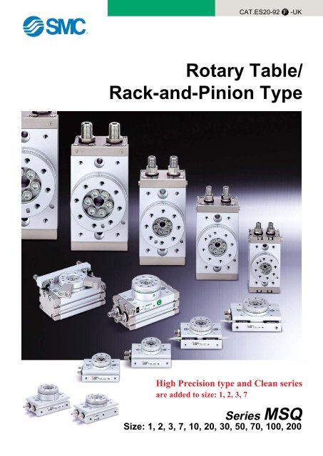
CAT.ES20-92F-UKRotary Table/Rack-and-Pinion TypeHigh Precision type and Clean seriesare added to size: 1, 2, 3, 7Series <strong>MSQ</strong>Size: 1, 2, 3, 7, 10, 20, 30, 50, 70, 100, 200
Compact rotary table with Low Table HeightEasy mounting of work piece.Table I.D/O.D tolerancesBasic type: <strong>MSQ</strong>B H9/h9High precision type: <strong>MSQ</strong>A H8/h8Positioning pin holeHollow axisAccommodates wiring and pipingfor equipment mounted on the tableTable inside and outside diametersFor alignment of rotation center and work piecePositioningpin holeFor position ofrotation directionLarge rolling elementbearing3 to 4 times higher axial load(compared with series CRQ)Rolling bearingHollow axisSize 1Hollow axis ø3.5Size 10Hollow axis ø52ø3.820ø93ø530ø97ø650ø10Pivoting angleadjustment range: 0 to 190 With internalshock absorber2 to 5 times more kinetic energy(compared with an adjustment bolt)70ø16100ø19200ø24Basic type<strong>MSQ</strong>BEasy mounting of bodyReference dia: Boss, HolePositioning pin holePin holeMounting from 2 directionsMovement in direction of table'sradial thrust: 0.01mm or lessBy using high precision bearing, the movement in thedirection of table’s radial thrust is reduced.High precision type<strong>MSQ</strong>AHigh precision typeHigh precisionbearingReference diameter(boss)Reference diameter(hole)Pin holeFeatures 1Piping from 2 directions (front and side) is possiblePiping position can be selected toaccommodate mounting conditionsA portSide directionA portFront directionB portB portSide direction
Basic type/<strong>MSQ</strong>BSize12371020305070100200With adjustment boltCleanWith internal shock absorberCleanHigh precision/<strong>MSQ</strong>ASize123710203050With adjustment boltCleanWith internal shock absorberClean: Additional seriesWith externalshockabsorber: Additional seriesWith externalshockabsorberHigh Precision type and Clean seriesare added to size: 1, 2, 3, 7NewModel Selection Procedure Formula Selection Example123Operating conditionsEnumerate the operating conditionsaccording to the mounting position.Vertical MountingRequired torqueConfirm the type of load as shownbelow, and select an actuator thatsatisfies the required torque.. Static load: Ts. Resistance load: Tf Load types. Inertial load: TaRotation timeSeries <strong>MSQ</strong>Model SelectionConfirm that it is within theadjustable range of rotation time.HFrM=Fr⋅LHorizontal MountingLGFSGM=FS⋅H. Model used. Operating pressure. Mounting orientation. Load typeTs (N⋅m)Tf (N⋅m)Ta (N⋅m). Load configuration. Rotation time t (s). Rotation angle θ (rad). Load mass m (kg). Distance between central axis andcenter of gravity H (mm). Mass point distance L (mm)Effective torque TsEffective torque (3 to 5) ⋅ TfEffective torque 10 ⋅ TaEffective torque0.2 to 1.0 s / 90 bRotary table: <strong>MSQ</strong>B50A, Pressure: 0.5 MPaMounting orientation: VerticalLoad type: Inertial load TaLoad configuration: 100 mm x 60 mm (Rectangular plate)Rotation time t: 0.3s, Rotation angle: 90 Load mass m: 0.4 kgDistance between centralaxis and centre of gravity H: 40 mmInertial load.10 x Ta = 10 x Ι x ωH= 10 x 0.00109 x (2 x ( / 2) / 0.3 2 )= 0.380 N⋅m Effective torque OKNote) I substitutes for t the value for inertial moment.G0.3 s / 90 OKaP.7INDEXSize: 1, 2, 3, 74Allowable loadConfirm that the radial load, thrustload and moment are within theallowable ranges.Thrust load: m x 9.8 Allowable loadMoment: m x 9.8 x H Allowable momentAllowable load0.4 x 9.8 = 3.92 N < Allowable load OK0.4 x 9.8 x 0.04 = 0.157 N⋅m0.157 N⋅m < Allowable moment OKP.12P.19Size: 10, 20, 3050, 70, 100200With externalshock absorberSize: 10, 2030, 505Inertial momentFind the load's inertial moment"Ι" for the energy calculation.Kinetic energy6Confirm that the load's kineticenergy is within the allowable value.Ι = m x (a 2 + b 2 ) / 12 + m x H 2Inertial moment1 / 2 x Ι x ω 2 allowable energyω = 2θ / t (ω: Terminal angular velocity)θ: Rotation angle (rad)t : Rotation time (s)Allowable kinetic energy/Rotation timeΙ = 0.4 x (0.10 2 + 0.06 2 ) / 12 + 0.4 x 0.04 2= 0.00109 kg⋅m 21/ 2 x 0.00109 x (2 x ( / 2) / 0.3) 2= 60 mJ Allowable energy OKFeatures 31
Model Selection Series <strong>MSQ</strong>Effective TorqueSize12371020305070100200Allowable LoadDo not allow the load and moment applied to the table to exceed theallowable values shown in the table below.(Operation beyond the allowable values can cause adverse effects onservice life, such as play in the table and loss of accuracy.)123710203050701002000.10.0170.0350.0580.110.180.370.550.91.362.033.960.20.0350.0710.120.220.360.731.091.852.724.057.92Allowableradial load (N)0.30.0520.110.170.330.531.101.642.784.076.0811.9Operating pressure (MPa)0.4 0.5 0.6 0.7 0.80.070 0.087 0.10 0.12 0.14 0.18 0.21 0.25 0.23 0.29 0.35 0.41 0.45 0.56 0.67 0.78 0.71 0.89 1.07 1.25 1.421.47 1.84 2.20 2.57 2.932.18 2.73 3.19 3.82 4.373.71 4.64 5.57 6.50 7.435.43 6.79 8.15 9.50 10.98.11 10.1 12.2 14.2 16.215.8 19.8 23.8 27.7 31.7Allowable thrust load (N)0.91.603.294.918.3512.218.235.6Note) Effective torque values are representative values and not to be considered as guaranteed values.Use them as a guide.Size: 1 to 7Effective torque (N⋅m)0.80.60.40.200Size0.1 0.2 0.3 0.4 0.5 0.6 0.7Operating pressure (MPa)7321Size: 10 to 50Effective torque (N⋅m)10864200 0.2 0.4 0.6 0.8 1Operating pressure (MPa)(a)(a)(b)50302010(b)Size: 70 to 200Effective torque (N⋅m)40302010Unit: N⋅m1.01.783.665.459.2813.620.339.600 0.2 0.4 0.6 0.8 1Operating pressure (MPa)Allowablemoment (N⋅m)High precisionHigh precisionHigh precisionBasic type Basic type Basic type Basic typetypetypetype313233547814719631433339054331323354861662333784145487174137197296296493740414548717413719729641454871781373634514767081009414548711071973985170.560.821.11.52.44.05.39.712.018.025.00.841.21.62.22.94.86.412.020010070High precisiontypeLoad TypesStatic load: TsA load as represented by the clamp which requirespressing force onlyDuring examination if it is decided to consider the mass of( the clamp itself in the drawing below, it should be regardedas an inertial load.)(Example)l(Example)ClampF: Pressing force (N)Static torque calculationTs = F x l (N⋅m)ShaftcenterResistance load: TfA load that is affected by external forces such asfriction or gravitySince the object is to move the load, and speedadjustment is necessary, allow an extra margin of 3to 5 times in the effective torque.∗Actuator effective torque (3 to 5) TfDuring examination if it is decided to consider the mass ofthe lever itself in the drawing below, it should be regardedas an inertial load.( )Mass mMovementLoadLeverFriction coefficient µF = µ mgStatic torque calculationTf = F x l (N⋅m)g = 9.8 m/s 2Inertial load: TaA load that must be rotated by the actuatorSince the object is to rotate the inertial load, andspeed adjustment is necessary, allow an extramargin of 10 times or more in the effectivetorque.lShaftcenter∗Actuator effective torque S . Ta(S is 10 times or more).Ta = I ⋅ (N⋅m)I: Inertial momentRefer to page 3..: Angular acceleration. 2θLoad = (rad/s 2 )t 2θ: Rotation angle (rad)t: Rotation time (s)Rotary actuator2
Series <strong>MSQ</strong>Inertial Moment Formula (Calculation of Inertial Moment Ι)Ι: Inertial moment kg⋅m 2 m: Load mass kgqThin shaft wThin shaft eThin rectangular plate rThin rectangular plate(Rectangular parallelopiped) (Rectangular parallelopiped)Position of rotational axis:Perpendicular to the shaftthrough one endPosition of rotational axis:Through the shaft's centre ofgravityPosition of rotational axis:Through the plate's centre ofgravityPosition of rotational axis:Perpendicular to the plate throughone of its points (also thesame in case of a thicker plate)Ι = m1 ⋅a1 2 a2+m2 ⋅23 3Ι = m ⋅a 212Ι = m ⋅a 212Ι = m1 ⋅+ m2 ⋅4a1 2 + b 2124a2 2 + b 212tThin rectangular plate(Rectangular parallelopiped) yCylinder(Including thin round plate)Position of rotational axis:Through the centre of gravity andperpendicular to the plate (alsothe same in case of a thickerplate)Position of rotational axis:Centre axisuSolid spherePosition of rotational axis:DiameteriThin round platePosition of rotational axis: DiameterΙ = m ⋅a 2 + b 212Ι = m ⋅r 2 2rΙ = m ⋅ 225Ι = m ⋅r 24oLoad at lever end!0Gear transmissionNumber of teeth= aΙ = m1 ⋅ + m2 ⋅ a2 2 + K3(Example) When shape of m2 is a sphere,2rrefer to 7, and K = m2 ⋅25a1 21. Find the inertial moment ΙB for therotation of shaft (B).2. Next, ΙB is entered to find ΙA the inertialmoment for the rotation of shaft (A) asaΙA = ( ) 2 ⋅ ΙBbKinetic Energy/Rotation TimeEven in cases where the torque required for rotation of the load is small, damage to internal parts may result from theinertial force of the load.Select models giving consideration to the load's inertial moment and rotation time during operation.(The inertial moment and rotation time charts can be used for your convenience in making model selections on page 4.)qAllowable kinetic energy and rotation time adjustment rangeFrom the table below, set the rotation time within the adjustment range for stable operation. Note that operation exceeding therotation time adjustment range, may lead to sticking or stopping of operation.Size12371020305070100200Withadjustment bolt11.5267254881240320560Allowable kinetic energy (mJ)With internalshock absorber39116116294110016002900With external shock absorberFor low energy For high energyNote) Refer to the note regarding the rotation time adjustment range on page 20.1615748051310Number of teeth= b231106012101820Rotation time adjustment range for stable operation s/90 Withadjustment bolt0.2 to 0.70.2 to 1.00.2 to 1.50.2 to 2.00.2 to 2.5With internalshock absorber0.2 to 0.70.2 to 1.0With externalshock absorberNote)0.2 to 1.0wInertial moment calculationSince the formula for inertial moment differ depending on the configuration of the load, refer to the inertial moment calculationformula on this page.3
Model Selection Series <strong>MSQ</strong>Kinetic Energy/Rotation TimeeModel selection Select models by applying the inertial moment and rotation time which have been found to the charts below.With adjustment boltInertial moment (kg⋅m 2 )10.10.010.0010.00010.00001<strong>MSQ</strong>B200A<strong>MSQ</strong>B100A<strong>MSQ</strong>B70A<strong>MSQ</strong>50A<strong>MSQ</strong>30A<strong>MSQ</strong>20A<strong>MSQ</strong>10A<strong>MSQ</strong>7A<strong>MSQ</strong>3A<strong>MSQ</strong>2A<strong>MSQ</strong>1AWith internal shock absorberInertial moment (kg⋅m 2 )10.10.010.001<strong>MSQ</strong>B200R<strong>MSQ</strong>B100R<strong>MSQ</strong>B70R<strong>MSQ</strong>50R<strong>MSQ</strong>10R<strong>MSQ</strong>20R·<strong>MSQ</strong>30R0.0000010.2 0.30.5 0.7 1.02.0 3.0Rotation time (s/90 )0.00010.2 0.3 0.4 0.5 0.6 0.7 0.8 0.9 1.0Rotation time (s/90 )With external shock absorberInertial moment (kg⋅m 2 )0.10.0510.0150.01<strong>MSQ</strong>50H<strong>MSQ</strong>50L<strong>MSQ</strong>30H<strong>MSQ</strong>20H<strong>MSQ</strong>30L<strong>MSQ</strong>20Lqw<strong>MSQ</strong>10H<strong>MSQ</strong>10Lq⋅ Inertial moment 0.015 kg⋅m 2⋅ Rotation time 0.45 s/90 <strong>MSQ</strong>20L is selected for the above.wLoad configuration: A cylinder of radius 0.5 m and mass 0.4 kgRotation time: 0.7 s/90 0.5 2Ι = 0.4 x = 0.05 kg⋅m22In the inertial moment and rotation time chart, find the intersection ofthe lines extended from the points corresponding to 0.05 kg⋅m 2 on thevertical axis (inertial moment) and 0.7 s/90 on the horizontal axis(rotation time). Since the resulting intersection point lines within the<strong>MSQ</strong>20L selection range, <strong>MSQ</strong>20L can be selected.0.0010.2 0.3 0.4 0.45 0.5 0.6 0.7 0.8 0.9 1.0Rotation time (s/90 )Rotation Accuracy: Displacement Value at 180° (reference value)Rotating amount of table topRotating amount of table sidemmMeasuring plate <strong>MSQ</strong>A <strong>MSQ</strong>BRotating amount of table topRotating amount of table side0.030.030.10.1Values in the table are actual values and not guaranteed values.4
Series <strong>MSQ</strong>Table Displacement (reference values)• The following graphs show the displacementat point A, which is 100 mm apart from thecenter of rotation, where the load is applied.100ALoad<strong>MSQ</strong>1ADisplacement<strong>MSQ</strong>10Displacement µm10080604020<strong>MSQ</strong>B1A (Basic type)<strong>MSQ</strong>A1A (High precision type)Displacement µm40035040302010<strong>MSQ</strong>B10 (Basic type)<strong>MSQ</strong>A10 (High precision type)01234 5Load N67890 5 10 15 20 25 30Load N<strong>MSQ</strong>2A<strong>MSQ</strong>20Displacement µm10080604020<strong>MSQ</strong>B2A (Basic type)<strong>MSQ</strong>A2A (High precision type)Displacement µm30025020019040302010<strong>MSQ</strong>B20 (Basic type)<strong>MSQ</strong>A20 (High precision type)0246Load N810120 10 20 30 40 50Load N<strong>MSQ</strong>3A100Displacement µm80604020<strong>MSQ</strong>B3A (Basic type)<strong>MSQ</strong>A3A (High precision type)<strong>MSQ</strong>30Displacement µm30025020015013050<strong>MSQ</strong>B30 (Basic type)<strong>MSQ</strong>A30 (High precision type)02468 10Load N121416180 10 20 30 40 50 60 70Load N<strong>MSQ</strong>7A<strong>MSQ</strong>50Displacement µm10080604020<strong>MSQ</strong>B7A (Basic type)<strong>MSQ</strong>A7A (High precision type)Displacement µm20015012050<strong>MSQ</strong>B50 (Basic type)<strong>MSQ</strong>A50 (High precision type)0246810 12 14Load N16182022240 20 40 60 80 100Load N1205
Rotary TableAir ConsumptionAir consumption is the volume of air which is expended by the rotary table's reciprocal operation inside the actuator and in thepiping between the actuator and the switching valve, etc. This is necessary for selection of a compressor and for calculation of itsrunning cost.∗The air consumption (QCR) required for one reciprocation of the rotary table alone is shown in the table below, and can be usedto simplify the calculation.FormulaeQCRQCPVPlaQCP+0.1QCR = 2V x x 10 30.1PQCP = 2 x a x l x x 10 60.1QC = QCR + QCP=======Air consumption of rotary tableAir consumption of tubing or pipingInternal volume of rotary tableOperating pressureLength of pipingInternal cross section of pipingAir consumption required for onereciprocation of rotary tableAir Consumption[l (ANR)][l (ANR)][cm 3 ][MPa][mm][mm 2 ][l (ANR)]When selecting a compressor, it is necessary to choose one whichhas sufficient reserve for the total air consumption of all pneumaticactuators downstream. This is affected by factors such as leakage inpipping, consumption by drain valves and pilot valves, etc., andreduction of air volume due to drops in temperature.FormulaQc2 = Qc x n x Number of actuators x Reserve factorQc2 = Compressor discharge flow rate[l /min(ANR)]n = Actuator reciprocations per minuteInternal cross section of tubing and steel pipingNominal sizeT 0425T 0604TU 0805T 08061/8BT 1075TU 1208T 12091/4BTS 16123/8BT 16131/2B3/4B1BO. D.(mm)46881012121616I. D.(mm)2.54566.57.5899.21212.71316.121.627.6Internal cross sectiona (mm 2 )4.912.619.628.333.244.250.363.666.5113127133204366598Size12371020305070100200RotationangleInternalvolume (cm 3 )0.661.32.24.26.6190 13.520.134.150.074.7145.90.10.00260.00520.00870.0170.0260.0540.0800.1360.2000.2990.5840.20.00390.00770.0130.0250.0400.0810.1210.2050.3000.4480.8750.30.00520.0100.0170.0330.0530.1080.1610.2730.4000.5981.1670.40.00650.0130.0220.0420.0660.1350.2010.3410.5000.7471.459Operating pressure (MPa)0.5 0.60.0078 0.00910.015 0.0180.026 0.0300.050 0.0580.079 0.0920.162 0.1890.241 0.2810.409 0.4770.600 0.7000.896 1.0461.751 2.043Air consumption of rotary table: QCR l (ANR)0.70.0100.0210.0350.0660.1060.2160.3220.5460.8001.1952.3340.80.1190.2430.3620.6140.9001.3452.6260.90.1320.2700.4020.6821.0001.4942.9181.00.1450.2970.4420.7501.1001.6433.2106
Rotary Table Series <strong>MSQ</strong>SpecificationsBasic typeSizeFluidMaximum operating pressureMinimum operating pressureAmbient and fluid temperatureCushionAngle adjustment rangeMaximum rotationCylinder bore sizePort size1 2 3 7Air (non-lube)0.7 MPa0.1 MPa0 to 60 C (with no freezing)NoneRubber bumper0 to 190 190 ø6 ø8 ø10 ø12M3M5Allowable Kinetic Energy and Rotation Time Adjustment RangeJIS symbolHigh precision typeSize1237Allowable kinetic energy (mJ)11.526Rotation time adjustment range for suitable operation (s/90˚)0.2 to 0.70.2 to 1.0Weight(g)Clean SeriesSize1 2 3 7Basic typeHigh precision type7580105115150165250265Note) Excluding the weight of auto switchesPrevents dispersion of the particles generated inside of the product into the clean room by sucking them out of the vacuum port on the body side.How to Order11 <strong>MSQ</strong>Clean SeriesVacuum typeABHigh precision typeBasic typeB 1 A E M9B SSize1237AAuto switchPort locationNilESide portFront portWith adjustment boltNumber ofauto switchesSpecifications and allowable loadParticle generation gradeSuction flow rate (example)Grade 1Note 1)1 l/min (ANR)11-<strong>MSQ</strong>A is identical to the high precision type and11-<strong>MSQ</strong>B is identical to the basic type.Note) Please refer to “Pneumatic Clean Series”catalogue for further details.DimensionsClean series products do not have a hollow axis.Basic type11-<strong>MSQ</strong>BAHigh precision type11-<strong>MSQ</strong>AAPA(Vacuum port)BKSize BK PA12375.37.59.57M3M3M3M5Dimensions other than above are identical tothe basic type and the high precision type.8
Series <strong>MSQ</strong>Rotation Direction and Rotation Angle• The rotary table turns in the clockwise direction when the A port is pressurized, and in the counter-clockwise direction when the B port is pressurized.• By adjusting the adjustment bolt, the rotation end can be set within the range shown in the drawing for the desired rotation angle.Counter-clockwisePositioning pin holeB portClockwiseWith adjust bolt, internal shock absorberSize1237A portB portAdjustment angle per rotation ofangle adjustment screw8.2 10.0 10.9 10.2 Adjustment bolt A(For counter-clockwiserotation end adjustment)Adjustment bolt B(For clockwiserotation end adjustment)Clockwise rotationadjustmentrange 95ClockwiseendNote) • The drawing shows the rotation range of the positioning pin hole.• The pin hole position in the drawing shows the counter-clockwiserotation end when the adjustment bolts A and B are tightenedequally and the rotation is adjusted 180 .5 Maximum rotation range22.5 Counter-clockwiserotationrange 95 end adjustment190 Rotation Range Example• Various rotation ranges are possible as shown in the drawings below using adjustment bolts A and B.(The drawings also show the rotation ranges of the positioning pin hole.)Adjustment bolt A(For counter-clockwiserotation end adjustment)Adjustment bolt B(For clockwiserotation end adjustment)Positioning pin holeAdjustment amount byadjustment bolt AAdjustment amount byadjustment bolt B190 (Maximum) RotationPin hole rotation range180 RotationAdjustment amount byadjustment bolt AAdjustment amount byadjustment bolt AAdjustment amount byadjustment bolt AAdjustment amountby adjustment bolt B90 RotationAdjustment amountby adjustment bolt B90 RotationAdjustment amountby adjustment bolt B90 Rotation9
Rotary Table Series <strong>MSQ</strong>Constructionq!8!7@0u@1 !6 !1 !2!8!7<strong>MSQ</strong>AA(High precision type)re!9o i @2 t !0 y !3!4!5@4@3wComponent partsNo.1234567891011121314Description Material No.Description MaterialBodyCoverAluminium alloyAluminium alloy1516Piston sealDeep groove ball bearingNBRBearing steelPlateAluminium alloyBasic typeDeep groove ball bearing17SealNBRHigh precision typeSpecial bearingBearing steelEnd coverPistonAluminium alloyStainless steel18Round head Philips screw No.0Round head Philips screwBasictypeSize: 1 to 3Size: 7Steel wirePinionChrome molybdenum steelRound head Philips screw High precision typeHexagon nutAdjustment boltCushion padTableBearing retainerMagnetWear ringSize: 3, 7Steel wireSteel wireRubber materialAluminium alloyAluminium alloyMagnetic materialResin192021222324Round head Philips screw No.0Hexagon socket head set boltParallel pinSeal washerHexagon socket head set screwO-ringSteel wireStainless steelCarbon steelNBRStainless steelNBR∗23 The hexagon socket head set screws are tightened at different positionsdepending on the position of the connecting port.10
Series <strong>MSQ</strong>Dimensions/Size 1, 2, 3, 7Basic type/<strong>MSQ</strong>BA1 YAYB effective depth YC2-PSide port(Plugged with a hexagonsocket head set screwwhen front ports are used.)2-JCDepth from bottom(not including JD) JE2-JUøDDøDøDEBHEffectivedepth 1.2Q(UU)Effective depth FBFDFAAWSDHBGAU(Max. approx. SU)JDBBSøDF(through)øDGBC2-PFront port(Plugged with a hexagonsocket head set screwwhen side ports are used.)AVSFAAYAX8-WD depth WE(Circumference: 8 equivalents)4-JJ depth JK2-J throughJA depth of counter bore JBWA1XAWB effective depth WC1Size1237DH DI DJ DL27h8 27.5h8 14H8 4.5H829h8 29.5h8 14H8 5 H833h8 34h8 17H8 6 H839h8 40h8 20H8 7 H8FE8.29.79.79.5HA13.515.515.516.5(mm)UV29.533.53639.522.5°BEBDBAWFXB effective depth XCHigh precision type/<strong>MSQ</strong>AAøDIøDHøDJSize1237Size1237A283034.541BC4.55.55.55.5AU2.83.64.44.8BD32343845AV1112.615.518.4BE1718.52330AW AX8.2 5.59.2 710.5 812.2 10BG BH11 8.212.6 9.215.5 10.518.4 12.2AY1.522.53BI30354050BA35374350BJ4.54.54.55(mm)BB39.645.146.759.2D DD DE27h9 27.5h9 14H929h9 29.5h9 14H933h9 34 h9 17H939h9 40 h9 20H9DF3.53.856DG4.5H95 H96 H97 H9BIFA4.85.35.36.5FB22.52.52.5FD3.74.24.24.5H9101011.5BJ2-JF depth JGJ3.33.34.24.2JA667.57.5JB3.53.54.54.5JCM4M4M5M5JD2.22.22.52.5FEHA(UV)øDL(mm)JE JF JG5.3 M4 45.3 M4 46 M4 46 M5 5Size1237JJM3M3M3M4JK3.53.53.54.5JUM3M4M5M6PM3M3M3M5Q S SD SF SU UU WA WB WC16 50.5 10.8 24.4 9.4 25 9.5 2H9 218 56 13.4 26.2 11.3 28 10 2H9 220.5 60 15.2 31 11.8 30.5 12 2H9 223 73.5 15.4 37.4 14.9 34.5 14 3H9 3WDM3M3M3M4WE4.85.35.36.5WF XA XB202122.5 2H924.5 2H925 27 2H929 32.5 3H9XC2223(mm)YA YB YC112H9 211.5 2H913.5 2H915.5 3H922311
Rotary Table/Rack-and-Pinion TypeSeries <strong>MSQ</strong>Size: 10, 20, 30, 50, 70, 100, 200Size10203050How to OrderHigh Precision TypeBasic Type<strong>MSQ</strong> A 10 A<strong>MSQ</strong> B 10 AM9BM9BAR10203050Size70100200With adjustment boltWith internal shock absorberNumber of auto switchesNilSn2 pcs.1 pc.n pcs.Auto switch typeNil Without auto switch (built-in magnet)∗ Refer to the table below for auto switch types.∗ The auto switch is included in the package (unmounted).Applicable auto switches/Refer to pages 25 through 31 for detailed auto switch specifications.TypeReed switchSolid state switchSpecialfunction——Diagnosticindication(2-colour display)Improvedwaterresistance(2-colour display)ElectricalentryGrommetGrommetIndicatorlightNoYesYesWiring(Output)2-wire3-wire(NPN equiv.)2-wire3-wire (NPN)3-wire (PNP)2-wireLoad voltageDC5 V12 V5 V, 12 V12 VAC24 V 5 V, 12 V 100 V or less—24 V3-wire (NPN)24 V 5 V, 12 V3-wire (PNP)2-wire—100 V—Auto switch typePerpendicularA90VA96VA93VM9NVM9PVM9BVM9NWVM9PWVM9BWV—In-lineA90A96A93M9NM9PM9BM9NWM9PWM9BWM9BA∗∗∗∗ Though it is possible to mount water resistant auto switch, the rotary table itself is not water resistance type.∗ Lead wire length symbols: 0.5 m Nil (Example) M9N3 m L (Example) M9NL5 m Z (Example) M9NZ∗ Solid state switches marked "" are produced upon receipt of order.12 VLead wire length (m) ∗0.5(Nil)—3(L)5(Z)———Applicable loadRelay, PLCIC circuit—— Relay, PLCIC circuit—Relay, PLCIC circuit—Made to Order Contact <strong>SMC</strong>.• –50 Without indicator light• –61 Flexible lead wire• Pre-wire connector12
Series <strong>MSQ</strong>SpecificationsJIS symbolHigh precision type/<strong>MSQ</strong>ABasic type/<strong>MSQ</strong>BSize10 20 30 50 70 100 200FluidAir (non-lube)Maximum With adjustment bolt1 MPaoperatingNote 1)pressure With internal shock absorber0.6 MPaMinimum Basic typeoperating0.1 MPapressure High precision type 0.2 MPa 0.1 MPa Ambient and fluid temperatureWith adjustment bolt0 to 60 C (with no freezing)Rubber bumperCushion With internal shock absorberShock absorberShock absorber RBA0805model -X692 RBA1006-X692 RBA1411-X692 RBA2015-X821 RBA2725-X821Angle adjustment rangeMaximum rotation0 to 190 Note 2)190 Cylinder bore sizeø15 ø18 ø21 ø25 ø28 ø32 ø40Port sizeEnd portsM5Rc 1/8Side portsM5Note 1) The maximum operating pressure of the actuator is restricted by the maximum allowable thrustof the shock absorber.Note 2) Be careful if the rotation angle of a type with internal shock absorber is set below the value in thetable below, the piston stroke will be smaller than the shock absorber's effective stroke, resultingin decreased energy absorption ability.SizeMinimum rotation angle that will not allowdecrease of energy absorption abilitySide ports1020 30 50 70 100 20052 43 40 60 71 62 82 Front portsAllowable Kinetic Energy and Rotation Time Adjustment RangeSizeAllowable kinetic energy (mJ)Withadjustment boltWithinternal shock absorberRotation time adjustment range for stable operation (s/90 )Withadjustment boltWithinternal shock absorber10739202511630481160.2 to 1.0 0.2 to 0.750812947024011000.2 to 1.510032016000.2 to 2.00.2 to 1.020056029000.2 to 2.5Note 1) Be careful if a type with internal absorber is used below the minimum speed, the energyabsorption ability will decrease drastically.Note1)Weight(g)SizeWith adjustment boltBasic typeWith internal shock absorberHigh precision With adjustment bolttype With internal shock absorber10530540560570209909901090109030129012901410141050208021002240226070288028901004090410020075807650Note) Values above do not include auto switch weights.13
Rotary Table Series <strong>MSQ</strong>Rotation Direction and Rotation Angle• The rotary table turns in the clockwise direction where the A port is pressurized, and in the counter-clockwise direction when the B portis pressurized.• By adjusting the adjustment bolt, the rotation end can be set within the ranges shown in the drawing for the desired rotation angle.• The rotation angle can also be set on a type with internal absorber.Positioning pin holeA portCounter-clockwise5 B portClockwiseWith adjust bolt, internal shock absorberSize1020305070100200Rotation Range ExampleAdjustment angle per rotation ofangle adjustment screw10.2°7.2°6.5°8.2°7.0°6.1°4.9°Adjustment bolt A(For counter-clockwiserotation end adjustment)Adjustment bolt B(For clockwiserotation end adjustment)Clockwise rotation endadjustment range 95 Clockwise22.5 95 adjustment rangeCounter-clockwiserotation endMaximum rotation range 190Note) • The drawing shows the rotation range of the positioning pin hole.• The pin hole position in the drawing shows the counter-clockwiserotation end when the adjustment bolts A and B are tightenedequally and the rotation is adjusted 180 .• Various rotation ranges are possible as shown in the drawings below using adjustment bolts A and B.(The drawings also show the rotation ranges of the positioning pin hole.)• The rotation angle can also be set on a type with inertial absorber.Positioning pin holeAdjustment amount byadjustment bolt AAdjustment bolt A(For counter-clockwiserotation end adjustment)Adjustment bolt B(For clockwiserotation end adjustment)Adjustment amountby adjustment bolt BPin hole rotation range190 (Maximum) Rotation 180 RotationAdjustment amount byadjustment bolt AAdjustment amount byadjustment bolt AAdjustment amount byadjustment bolt AAdjustment amountby adjustment bolt BAdjustment amountby adjustment bolt BAdjustment amountby adjustment bolt B90 Rotation 90 Rotation 90 Rotation14
Series <strong>MSQ</strong>Clean SeriesPrevents dispersion of the particles generated inside of the product into the clean room by sucking them out of the vacuum port on the body side.How to Order11 <strong>MSQ</strong>Clean seriesVacuum typeABHigh precision typeBasic typeB 10 A A90 SSize10203050ARNumber ofauto switchesAuto switch typeWith adjustment boltShock absorberSpecifications and Allowable LoadParticle generation gradeSuction flow rate (example)Note 1)Grade 11 l/min (ANR)11-<strong>MSQ</strong>A is identical to the high precision type and11-<strong>MSQ</strong>B is identical to the basic type.Note) Please refer to “Pneumatic Clean Series”catalogue for further details.DimensionsClean series products do not have a hollow axis.Basic type11-<strong>MSQ</strong>BA11-<strong>MSQ</strong>BRøDAøDBøDCøDDM5 x 0.8 depth 5(Vacuum port)5.511.5HBHC(HD)Size10203050DA(h9)46616777DB(h9)45606575DC(H9)20283235DD(h9)35404854HB20222224Dimensions other than above are identical to the basic type.HC5667(mm)HD59656877High precision type11-<strong>MSQ</strong>AA11-<strong>MSQ</strong>ARøDAøDBøDCøDDM5 x 0.8 depth 5(Vacuum port)HEHAHBHC(HD)Size10203050DA(h8) DB(h8) DC(H8) DD(h8)46616777456065752028323535404854HA15.519.519.521.5HB24303034HC5667Dimensions other than above are identical to the high precision type.HD63737687(mm)HE9.513.513.515.515
Rotary Table Series <strong>MSQ</strong>Construction<strong>MSQ</strong> R(With internal shock absorber)@0 !3 #0 @9 q @2 @0 @3u @6!9!4!5!2@1<strong>MSQ</strong>A (High precision type)Parts listNo.123456789101112131415161718BodyCoverPlateSealEnd coverPistonPinionHexagon nut with flangeHexagon nutAdjustment boltCushion padSeal retainerGasketGasketTableBearing retainerMagnetWear ringPiston sealDescription Material No.Description Material192021 Round head philips screw No.0Deep groove ball bearingDeep groove ball bearingSize: 10 to 50Basic typeNeedle bearingAngular contact ball bearingSize: 70 to 200High precision typeBearing steelBearing steelSize: 10 to 50Size: 70 to 200#1 o i @7 @8 t !0 y !6 !7 !8 !1 @5 er w@4Aluminium alloyAluminium alloyAluminium alloyNBRAluminium alloyStainless steelChrome molybdenum steelSteel wireChrome molybdenum steelRubber materialAluminium alloyNBRNBRAluminium alloyAluminium alloyMagnetic materialResinNBR22232425262728293031Round head philips screw Size: 10Low head cap screw Size: 20 to 50Hexagon socket head set bolt Size: 70 to 200Hexagon socket head set boltHexagon sockethead set boltCS type snap ringParallel pinParallel keySeal washerPlugO-ringSteel ballsShock absorberSize: 10 to 50Size: 70 to 200Size: 10 to 50Size: 70 to 200Size: 70 to 200 onlySize: 70 to 200 onlySteel wireStainless steelChrome molybdenum steelStainless steelStainless steelCarbon steelSpring steelCarbon steelNBRBrassNBRStainless steel—Replacement partsDescriptionSeal kit10KT-<strong>MSQ</strong>1020KT-<strong>MSQ</strong>2030KT-<strong>MSQ</strong>30Kit no.50KT-<strong>MSQ</strong>5070KT-<strong>MSQ</strong>70100KT-<strong>MSQ</strong>100200KT-<strong>MSQ</strong>200NoteA set of above numbers r, !2, !3, !7, !8 and @716
Series <strong>MSQ</strong>Dimensions/Size 10, 20, 30, 50Basic type/<strong>MSQ</strong>BAYA 2ViewYB effectivedepth YC2-JC depth JD2-JUCBCAøDDøDøDEEffectivedepth FBFDFAHQ(UU)SEBB2-PPiping portAWBCAU(Max. approx. SU)BASøDF(Through)øDGEffectivedepth FCBASDAYAXAVSFAAAXB effectivedepth XC8-WD depth WE(Circumference: 8 equivalents)4-JJ depth 82-J throughJA counter boredepth JBXA 2WA 245 22.5 WB effective depth WCBE2-M5 x 0.8Piping port (Plugged)With internal shock absorber<strong>MSQ</strong>AR<strong>MSQ</strong>BRBDHigh precision type<strong>MSQ</strong>AA/With adjustment bolt<strong>MSQ</strong>AR/With internal shock absorberøDIøDHøDJWF(Max. approx. FU)Size10203050(mm)FU31.534.734.751.7FEHAøDK (Through)øDL(UV)Size10203050DH DI DJ45h8 46h8 20H860h8 61h8 28H865h8 67h8 32H875h8 77h8 35H8DK59910DL FE15H8 1017H8 15.522H8 16.526H8 17.5HA18.5262730(mm)UV52.5636776Size10203050AA55.470.875.485.4A50657080AU AV8.6 2010.6 27.510.6 2914 38AW15.51618.522AX12141419AY4556BA9.5121215.5BB34.5465063BC27.8303237.5BD607684100BE27343750CA4.566.510CB D DD DE28.5 45h9 46h9 20H930.5 60h9 61h9 28H933.5 65h9 67h9 32H937.5 75h9 77h9 35H9DF59910DG15H917H922H926H9FA8101012FB464.55FC32.533FD4.56.56.57.5H13171720J6.88.68.610.5JA11141418(mm)JB6.58.58.510.5Size10203050JCM8M10M10M12JD12151518JJM5M6M6M8JUM8 x 1M10 x 1M10 x 1M14 x 1.5PM5M5Rc 1/8Rc 1/8Q34374046S SD92 9117 10127 11.5152 14.5SE13121415SF45606575SU UU17.7 4725 5425 5731.4 66WA WB WC15 3H9 3.520.5 4H9 4.523 4H9 4.526.5 5H9 5.5WDM5M6M6M8WE8101012WF32434855XA27363945XB3H94H94H95H9XC3.54.54.55.5YA19242833(mm)YB YC3H94H94H95H93.54.54.55.517
Rotary Table Series <strong>MSQ</strong>Dimensions/Size 70, 100, 200Basic type/<strong>MSQ</strong>BAViewYA 2YB effectivedepth YC2-JC depth JD2-M5 x 0.8 (plug)Port size2-JU9øDDøDøDEEffectivedepth FBFAHABBB2-Rc 1/8Port size30 (Max. approx. SU)8BASøDF(Through)øDGXB effective depth XCBAFDEffectivedepth FCWB effective depth WCQ(UU)SD 15AXAYAVSFAAAAWCBBC8-WD depth WE(Circumference: 8 equivalents)4-JJ depth JK2-J throughJA counter boredepth JBXA 2WA 245 22.5 BEBDWFWith shock absorber<strong>MSQ</strong>BR(mm)Size FU70 55.4100 55.5200 79.5(Max. approx. FU)Size70100200AA90101119AB92102120A8495113AV425060AW25.529.536.5AX272736AY8810BA171724BB7585103BC44.550.565.5BD110130150BE576680CB364257D DD DE88h9 90h9 46H998h9 100h9 56H9116h9 118h9 64H9DF161924DG FA22H9 12.524H9 14.532H9 16.5FB569FC3.53.55.5FD91215H222732J10.410.414.2JA17.517.520(mm)JB10.510.512.5Size70100200JCM12M12M16JD181825JJM8M8M12JK101013JUM20 x 1.5M20 x 1.5M27 x 1.5Q535974S170189240SD182229SF7990108SU UU34.234.3758640.2 106WA WB WC32.5 5H937.5 6H95.56.544 8H9 8.5WDM8M10M12WE WF12.5 6714.5 7716.5 90XA545969XB5H96H98H9XC3.54.54.5YA394954(mm)YB YC5H96H98H93.54.56.518
Rotary Table/Rack-and-Pinion TypeSeries <strong>MSQ</strong>With External Shock AbsorberSize: 10, 20, 30, 50How to Order<strong>MSQ</strong>B10L2M9BSABHigh precision typeBasic typeLHSize10203050Shock absorber typeShock absorber for low energyShock absorber for high energyNumber of auto switchNilSn2 pcs.1 pc.n pcs.Auto switch typeNil Without auto switch (Built-in magnet)∗Refer to the table below for auto switch types.∗The auto switch is included in the package (unmounted).2345StandardtypeSymmetrictype180 90 180 90 Refer to the table to the right.Port location/RotationRotation180 90 2: Standard type, 180 3: Standard type, 90 4: Symmetric type, 180 Connecting port positionSymmetric type Standard typeConnecting portConnecting portConnecting port5:Symmetric type, 90 Connecting portApplicable auto switches/Refer to pages 25 through 31 for detailed auto switch specifications.TypeReed switchSolid state switchSpecialfunctionDiagnosticindication(2-colourdisplay)ElectricalentryGrommetGrommetIndicatorlightNoYesYesWiring(Output)2-wire3-wire(NPN equiv.)Load voltageDC5 VAC24 V 5 V, 12 V 100 V or less2-wire3-wire (NPN)24 V 12 V5 V, 12 V3-wire (PNP)2-wire12 V3-wire (NPN) 24 V5 V, 12 V3-wire (PNP)100 VAuto switch typePerpendicularA90VA96VA93VM9NVM9PVM9BVM9NWVM9PWVM9BWVIn-lineA90A96A93M9NM9PM9BM9NWM9PWM9BW∗∗M9BAImprovedwaterresistance2-wire12 V(2-colour display)∗∗ Though it is possible to mount water resistant auto switch, the rotary table itself is not water resistance type.∗ Lead wire length symbols: 0.5 m Nil (Example) M9N3 m L (Example) M9NL5 m Z (Example) M9NZ∗Solid state switches marked "" are produced upon receipt of order.Lead wire length (m) ∗0.5(Nil)3(L)5(Z)Applicable loadRelay, PLCIC circuit Relay, PLCIC circuitRelay, PLCIC circuitMade to Order Contact <strong>SMC</strong>.• –50 Without indicator light• –61 Flexible lead wire• Pre-wire connector19
Rotary Table Series <strong>MSQ</strong>SpecificationsSizeFluidMaximum operating pressureMinimum operating pressureAmbient and fluid temperatureCushionShock absorbertypeRotationAngle adjusting rangeCylinder bore sizePort sizeFor low energyFor high energyEnd portsSide ports10 20 30 50Air (non-lube)1 MPa0.2 MPa0 to 60 C (with no freezing)RB0805RB0806Shock absorberRB1006RB100790 , 180 Each rotation end 3 RB1411RB1412ø15 ø18 ø21 ø25M5Rc 1/8M5JIS symbolSide portsFront portsAllowable Kinetic Energy and Rotation Time Adjustment RangeSize10203050Allowable kinetic energy (mJ)Shock absorber for low energy Shock absorber for high energy1612315741060805121013101820SizeFor low energyFor high energyRotation time adjustment rangefor stable operation (s/90 )Note)0.2 to 1.0Note) Values above indicate the time between the start of rotation and the deceleration caused bythe shock absorber. Although the time required by the rotary table to reach the rotation endafter deceleration differs depending on the operating conditions (inertial moment of theload, rotation speed and operating pressure), approximately 0.2 to 2 seconds are required.The range of angles within which the shock absorber operates is between the rotation endand the values shown below.102030508.6 8.0 7.3 10.5 7.1 6.9 6.2 9.6 Weight(g)Size90 specificationBasic type180 specificationHigh precision 90 specificationtype 180 specification10630600700670Note) Values above do not include auto switch weights.20 30 5012001140139013401520145017501680248023702810269020
Series <strong>MSQ</strong>Rotation Direction and Rotation Angle. The rotary table turns in the clockwise direction where the A port is pressurized, and in the counter-clockwise direction when the B port is pressurized.. By adjusting the shock absorber, the rotation end can be set within the ranges shown in the drawing.Standard typeFor 180 For 90 A portCounter-clockwiseA portPositioning pin hole3 A portPositioning pin hole3 3 3 B portClockwise3 3 Clockwise180 22.5 Maximum rotation174 Minimum rotation range186 range3 Clockwise322.5 rotation range 84 Minimum90 Maximum96 rotation rangePositioning pin holePositioning pin holePosition of bottom positioning pin holePosition of bottom positioning pin holeSymmetric typeFor 180 For 90 Positioning pin holePositioning pin holeCounter-clockwiseB port3 3 A port22.5 3 3 3 180 A port22.5 3 ClockwiseA portClockwiseMinimum rotation rangeMaximum rotation174 186 range3 Clockwise3 rotation range 84 Minimum90 rotation range 96 MaximumPositioning pin holePositioning pin holePosition of bottom positioning pin holePosition of bottom positioning pin holeWith external shock absorberSize10203050Adjustment angle per rotation of angle adjustment screw1.4 1.2 1.1 1.3 Note) ⋅ The drawings show the rotation range for the top positioning pinhole of the table.⋅ The pin hole position in the drawing shows the counter-clockwiserotation end when the shock absorbers are tightened equallyand the rotation is adjusted to 180 and 90 .21
Rotary Table Series <strong>MSQ</strong>Constructioniy u qe t r w oComponent partsNo.123456789DescriptionEnd coverTableArmShock absorber holderHexagon socket head set boltHexagon socket head set boltTaper plugHexagon nutShock absorberMaterialAluminium alloyAluminium alloyChrome molybdenum steelAluminium alloyStainless steelStainless steelSteel wireSteel wireReplacement partsDescriptionSeal kit10P523010-620P523020-6Kit no.30P523030-650P523040-6NoteSeal washer @7 is excluded from the kit contents described on page 16.22
Rotary Table Series <strong>MSQ</strong>Proper Auto Switch Mounting Position at Rotation End Size: 1 to 7AABBWhen D-M9 and M9 are usedWhen D-F8 is usedSize1237Rotation190°190°190°190°A20.922.824.428.7D-M9WOperatingangle θ m40°35°30°25°Hysteresisangle10°10°10°10°A20.922.824.428.7Solid state switchD-M9Operating Hysteresisangle θ m angle55°45°40°40°10°10°10°10°B16.918.820.424.7Operating angle θ m: Value of the operating range Lm of a single auto switch converted to an axial rotation angle.Hysteresis angle : Value of auto switch hysteresis converted to an angle.D-F8Operatingangle θ m20°20°15°15°Hysteresisangle10°10°10°10° Size: 10 to 200BAMagnetOperating range at propermounting position (Lm/2)Most sensitive positionOperating range ofsingle auto switch LmSize1020305070100200Rotation190°190°190°190°190°190°190°A17232733374457B365066687891115Reed switchD-A9, D-A9VOperatingangle θ m90°80°65°50°45°40°35°Hysteresisangle10°10°10°10°10°10°10°A21273137414861Solid state switchD-M9W,D-M9WV, D-M9BALB40546072829519Operatingangle θ m90°80°65°50°45°40°35°Hysteresisangle10°10°10°10°10°10°10°Operating angle θ m: Value of the operating range Lm of a single auto switch converted to an axial rotation angle.Hysteresis angle : Value of auto switch hysteresis converted to an angle.A21273137414861B40546072829519D-M9Operatingangle θ m60°50°50°40°40°30°20°Hysteresisangle10°10°10°10°10°10°10°24
Series <strong>MSQ</strong>Auto Switch SpecificationsAuto Switch Common SpecificationsTypeLeakage currentOperating timeImpact resistanceInsulation resistanceWithstand voltageAmbient temperatureEnclosureReed switchSolid state switchNone3-wire: 100 µA or less, 2-wire: 0.8 mA or less1.2 ms1 ms or less300 m/s 21000 m/s 250 MΩ or more at 500 VDC (Between lead wire and case)1000 VAC for 1 min.(Between lead wire and case)10 to 60 CIEC529 standard IP67, JISC0920 watertight construction1000 VAC for 1 min.(Between lead wire and case)Lead Wire LengthLead wire length indication(Example)D-M9P LLead wire lengthNil 0.5 mL 3 mZ 5 mNote 1) Lead wire length Z: Auto switch applicable to 5 m lengthSolid state switch: All types are produced upon receipt of order(standard procedure).Note 2) For solid state switches with flexible lead wire specification, add "-61"at the end of the lead wire length.Contact Protection Boxes/CD-P11, CD-P12D-A9/A9VThe above auto switches do not have internal contact protection circuits.1. The operating load is an induction load.2. The length of wiring to the load is 5 m or more.3. The load voltage is 100 VAC.Use a contact protection box in any of the above situations.The life of the contacts may otherwise be reduced. (They may stay ONall the time.)SpecificationsPart numberLoad voltageMaximum load currentCD-P11100 VAC 200 VAC25 mA 12.5 mA∗ Lead wire lengthSwitch connection side 0.5 mLoad connection side 0.5 mCD-P1224 VDC50 mAInternal circuitsCD-P11Surge absorberChokecoilOUT BrownOUT BlueCD-P12Zener diodesChoke coilOUT (+)BrownOUT ()BlueDimensionsConnection25To connect a switch to a contact protection box, connect the lead wirefrom the side of the contact protection box marked SWITCH to the leadwire coming out of the switch. Furthermore, the switch unit should be keptas close as possible to the contact protection box, with a lead wire lengthof no more than 1 meter between them.
Basic WiringSeries <strong>MSQ</strong>Auto Switch Connections and ExamplesSolid state 3-wire, NPNMainswitchcircuitBrownLoadBlackBlueSolid state 3-wire, PNPMainswitchcircuitBlackBrownBlueLoad2-wireMainswitchcircuitLoadBrownBlue2-wireIndicatorlight,protectioncircuit,etc.BrownLoadBlue(Power supplies for switch and loadare separate.)MainswitchcircuitBrownLoadBlackBlueMainswitchcircuitBrownLoadBlueIndicatorlight,protectioncircuit,etc.BrownBlue LoadExamples of Connection to PLC (Programmable Logic Controller)Sink input specifications3-wire, NPNBrownSwitchBlack InputSource input specifications3-wire, PNPBrownSwitchBlackInputConnect according to the applicablePLC input specifications, as theconnection method will vary dependingon the PLC input specifications.BlueBlue2-wireBrownCOMInputPLC internal circuit2-wireBlueCOMInputPLC internal circuitSwitchSwitchBlueCOMPLC internal circuitBrownConnection Examples for AND (Series) and OR (Parallel)3-wireAND connection for NPN output(using relays)Switch 1Switch 2BrownBlackBlueBrownBlackBlueRelayRelayLoadRelaycontactSwitch 1Switch 2BrownBlackBrownCOMAND connection for NPN output(performed with switches only)BlueBlackBlueLoadPLC internal circuitOR connection for NPN outputSwitch 1Switch 2BrownBlackBlueBrownBlackBlueLoad2-wire with 2 switch AND connectionSwitch 1Switch 2BrownBlueBrownBlueLoadWhen two switches areconnected in series, a loadmay malfunction becausethe load voltage will declinewhen in the ON state.The indicator lights willlight up if both of the switchesare in the ON state.Load voltage at ON =Power supplyResidualvoltage voltagex 2 pcs.= 24 V 4 V x 2 pcs.= 16 VExample: Power supply is 24 VDCVoltage drop in switch is 4 VThe indicator lights will light up whenboth switches are turned ON.2-wire with 2 switch OR connectionSwitch 1Switch 2BrownBlueBrownBlueLoadWhen two switchesare connected inparallel, malfunctionmay occur becausethe load voltage willincrease when inthe OFF state.Load voltage at OFF =Leakagex 2 pcs. x Loadcurrentimpedance= 1 mA x 2 pcs. x 3 kΩ= 6 VExample: Load impedance is 3 kΩLeakage current from switch is 1 mABecause there is no currentleakage, the load voltagewill not increase when turnedOFF. However, dependingon the number of switchesin the ON state, the indicatorlights may sometimesget dark or not light up,because of dispersion andreduction of the current flowingto the switches.26
Reed Switches: Direct Mounting TypeD-A90(V), D-A93(V), D-A96(V)GrommetElectrical entry: In-lineCautionPrecautionsqWhen securing the switch, be sure to usethe fixing screws attached to the autoswitch body. The switch may be damagedif screws other than specified ones areused.Auto Switch Internal CircuitsD-A90VD-A93VReed switchReed switchLEDResistorZener diodeBrown (Red)Blue (Black)ContactprotectionboxCD-P11CD-P12ContactprotectionboxCD-P11CD-P12OUT ()BrownOUT ()BlueOUT (+)BrownOUT (–)BlueAuto Switch SpecificationsD-A90, D-A90V (without indicator light)Auto switch part no.D-A90, D-A90VApplicable loadLoad voltageMax. load currentContact protection circuitInternal resistanceD-A93, D-A93V, D-A96, D-A96V (with indicator light)Auto switch part no.D-A93, D-A93VD-A96, D-A96VApplicable loadLoad voltageLoad current rangeand Max. loadcurrentContact protection circuitNoneInternal voltage drop D-A93 2.4 V or less (to 20 mA)/3 V or less (to 40 mA)D-A93V 2.7 V or less0.8 V or lessIndicator lightRed LED lights when ONLead wireD-A90(V), D-A93(V) Oil proof heavy duty vinyl cable, ø2.7, 0.18 mm 2 x 2 cores (brown, blue), 0.5 mD-A96(V)Oil proof heavy duty vinyl cable, ø2.7, 0.15 mm 2 x 3 cores (brown, black, blue), 0.5 mNote 1) Refer to page 25 for reed switch common specifications.Note 2) Refer to page 25 lead wire length.WeightModelLead wire length 0.5 mLead wire length 3 mDimensionsD-A90, D-A93, D-A96IC circuit, Relay, PLCACACAC24 V DC or less48 V DC or less 100 V DC or less50 mA40 mANone20 mA1 Ω or less (Includes the lead wire length of 3 m)24 VDC5 to 40 mAD-A90630M2.5 x 4 lSlotted set screwRelay, PLCD-A90V630100 VAC5 to 20 mAD-A93630For details about certified products conforming tointernational standards, visit us at www.smcworld.com.PLC: Programable Logic ControllerD-A93V630IC circuit4 to 8 VDCD-A96841Indicator lightType D-A90 iswithout indicator light20 mAUnit: gD-A96V841D-A96VReed switchLEDResistorReversecurrentpreventiondiodeDC (+)BrownOUTBlackDC (-)BlueLoadNote) qThe operating load is the induction load.wThe wiring length to the load is 5 m or more.eThe load voltage is 100 VACUnder any of the above conditions, the life time ofthe contact may be shortened. Please use acontact protection box. (Please refer to page 19for more information on the contact protectionbox.)(+)DC power(–)D-A90V, D-A93V, D-A96VM2.5 x 4 lSlotted set screwMost sensitive positionType D-A93 dimensions are shown inside ( ).Most sensitive position27Indicator lightType D-A90V iswithout indicator light
Solid State Switches/Direct Mounting TypeD-M9N, D-M9P, D-M9BGrommet 2-wire load current is reduced(2.5 to 40 mA). Lead-free Use of lead wire compliantwith UL standards (style 2844)CautionOperating PrecautionsWhen the cable sheath is stripped, confirmthe stripping direction.The insulator may be split or damageddepending on the direction.Auto Switch SpecificationsPLC: Programable Logic ControllerD-M9 (with indicator light)Switch modelD-M9N D-M9PD-M9BWiring type3-wire2-wireOutput typeNPNPNP–Applicable loadIC circuit, Relay, PLC24 VDC relay, PLCPower supply voltage5, 12, 24 VDC (4.5 to 28 V)–Current consumption10 mA or less–Load voltage28 VDC or less –24 VDC (10 to 28 VDC)Load current40 mA or less2.5 to 40 mAInternal voltage drop0.8 V or less4 V or lessLeakage current100 µA or less at 24 VDC0.8 mA or lessIndicator lightRed LED lights when ON Lead wire ······ Oil proof heavy duty vinyl cable: 2.7 x 3.2 ellipseD-M9B0.15 mm 2 x 2 coresD-M9N, D-M9P 0.15 mm 2 x 3 coresNote 1) Refer to page 25 for solid state auto switch common specifications.Note 2) Refer to page 25 for lead wire length.WeightAuto switch modelLead wire length(m)0.535D-M9N84168For details about certified products conforming tointernational standards, visit us at www.smcworld.com.D-M9P84168D-M9B73863Unit: gAuto Switch Internal CircuitD-M9NSwitchmain circuitDC (+)BrownOUTBlackDimensionsD-M9D-M9B, N, PMounting screw M2.5 x 4 lSlotted set screwIndicator light2.6DC (–)Blue42.8222.7D-M9PD-M9N, P (3-wire)3.2DC (+)BrownOUTBlackD-M9B (2-wire)6Most sensitive position223.2D-M9BDC (–)Blue6Most sensitive position22OUT (+)BrownSwitchmain circuitSwitchmain circuitOUT (–)Blue28
Solid State Switches: Direct Mounting TypeD-M9NV, D-M9PV, D-M9BVGrommet 2-wire load current is reduced (2.5 to 40 mA). Lead-free Use of lead wire compliant with ULstandards (style 2844) 1.5 times the flexibility compared withconventional products (comparison withother <strong>SMC</strong> products)ConventionalD-M9CautionOperating PrecautionsWhen the cable sheath is stripped, confirmthe stripping direction.The insulator may be split or damageddepending on the direction.Auto Switch SpecificationsPLC: Programable Logic ControllerD-M9 (with indicator light)Switch modelD-M9N D-M9PD-M9BWiring type3-wire2-wireOutput typeNPNPNP–Applicable loadPower supply voltageCurrent consumptionIC circuit, Relay, PLC5, 12, 24 VDC (4.5 to 28 V)10 mA or less24 VDC relay, PLC––Load voltage28 VDC or less –24 VDC (10 to 28 VDC)Load currentInternal voltage drop40 mA or less0.8 V or less2.5 to 40 mA4 V or lessLeakage currentIndicator light100 µA or less at 24 VDCRed LED lights when ON0.8 mA or less Lead wire ······ Oil proof heavy duty vinyl cord: 2.7 × 3.2 ellipseD-M9B0.15 mm 2 × 2 coresD-M9N, D-M9P 0.15 mm 2 × 3 coresNote 1) Refer to page 15 for solid state auto switch common specifications and lead wire length.WeightAuto switch modelLead wire length mDimensions0.53D-M9N(V)841Refer to www.smcworld.com for details ofproducts compatible with overseas standards.D-M9P(V)841D-M9B(V)738Unit: gD-M9VAuto Switch Internal CircuitD-M9N, D-M9NVDC (+)BrownSwitchmain circuitOUTBlackMounting screwSlotted set screwIndicator lightDC (–)BlueD-M9P, D-M9PVDC (+)BrownMost sensitive positionSwitchmain circuitOUTBlackDC (–)BlueD-M9B, D-M9BVOUT (+)BrownSwitchmain circuitOUT (–)Blue29
2-color Display Solid State Switches/Direct Mounting TypeD-M9NW(V), D-M9PW(V), D-M9BW(V)GrommetAuto Switch Internal CircuitsD-M9NW, M9NWVMainswitch circuitD-M9PW, M9PWVDC (+)BrownOUTBlackDC (–)BlueDC (+)BrownAuto Switch SpecificationsD-M9W, D-M9WV (with indicator light)Auto switch part no.Electrical entry directionIndicator lightWeightAuto switch modelLead wire length(m)D-M9NWIn-line0.535D-M9NWVPerpendicularD-M9PWIn-lineD-M9NW(V)73456PLC: Programable Logic ControllerD-M9PWVPerpendicularWiring type3-wireOutput typeNPNPNPApplicable loadPower supply voltageCurrent consumptionIC circuit, Relay, PLC5, 12, 24 VDC (4.5 to 28 V)10 mA or lessLoad voltageLoad currentInternal voltage drop28 VDC or less40 mA or less1.5 V or less(0.8 V or less at 10 mA load current)80 mA or less0.8 V or lessLeakage voltage100 µA or less at 24 VDCFor details about certified products conforming tointernational standards, visit us at www.smcworld.com.D-M9PW(V)73456D-M9BWIn-lineActuated positionRed LED light upOptimum operating positionGreen LED light up2-wireD-M9BWVPerpendicular24 VDC relay, PLC24 VDC (10 to 28 VDC)5 to 40 mA4 V or less0.8 mA or lessLead wire Oil proof heavy duty vinyl cable, ø2.7, 0.15 mm 2 x 3 cores (brown, black, blue),0.18 mm 2 x 2 cores (brown, blue), 0.5 mNote 1) Refer to page 25 for solid state switch common specifications.Note 2) Refer to page 25 for lead wire length.Unit: gD-M9BW(V)73252Mainswitch circuitOUTBlackDimensionsDC (–)BlueD-M9W2.64D-M9BW, M9BWV6Most sensitive positionMainswitch circuitOUT (+)BrownOUT (–)BlueD-M9WV2.8222Mounting screw M2.5 x 4 lSlotted set screwIndicator lightø2.7ø2.73.8Indicator light/Display methodOperatingrangeONIndicatorRedGreenRedOFF4.326Most sensitive positionMounting screw M2.5 x 4 lSlotted set screwIndicator light6.23.14Optimumoperating position4.62.82030
Solid State Switches/Direct Mounting TypeD-F8N, D-F8P, D-F8BGrommetCautionPrecautionsWhen securing the switch, be sure to usethe fixing screws attached to the auto switchbody. The switch may be damaged if screwsother than specified ones are used.Auto Switch SpecificationsAuto switch part no.Electrical entry directionWiring typeOutput typeApplicable loadPower supply voltageCurrent consumptionLoad voltageLoad current1.5 V or lessInternal voltage drop(0.8 V or less at 10 mA load current)Leakage currentIndicator lightPLC: Programable Logic ControllerD-F8ND-F8PD-F8BPerpendicular PerpendicularPerpendicular3-wire2-wireNPNPNPIC circuit, 24 VDC relay, PLC24 VDC relay, PLC5, 12, 24 VDC (4.5 to 28 V)10 mA or less28 VDC or less24 VDC (10 to 28 V)40 mA or less 80 mA or less2.5 to 40 mA0.8 V or less100 µA or less at 24 VDCLead wireHeavy duty oil resistant vinyl cable, ø2.7, 0.5 mD-F8N, D-F8P 0.15 mm 2 x 3 wire (Brown, Black, Blue)D-F8B 0.18 mm 2 x 2 wire (Brown, Blue)Note 1) Refer to page 25 for solid state switch common specifications.Note 2) Refer to page 25 for lead wire length.For details about certified products conforming tointernational standards, visit us at www.smcworld.com.Red LED light when ON4 V or less0.8 mA or less at 24 VDCAuto Switch Internal CircuitsD-F8NMainswitch circuitDC (+)BrownOUTBlackWeightAuto switch modelLead wire length(m)0.535D-F8N73252D-F8P73252Unit: gD-F8B73252D-F8PDC (–)BlueDimensionsD-F8N, D-F8P, D-F8BDC (+)Brownø2.7D-F8BMainswitch circuitOUTBlackDC (–)Blue8Most sensitive position3.1 10.9 34Switch Mainswitch Main circuitOUT (+)Brown4.32Mounting screw M2.5 x 4 lSlotted set screwIndicator lightOUT (–)Blue2.8104.631
Series <strong>MSQ</strong>Safety InstructionsThese safety instructions are intended to prevent a hazardous situation and/orequipment damage. These instructions indicate the level of potential hazard bylabels of "Caution", "Warning" or "Danger". To ensure safety, be sure toobserve ISO 4414 Note 1) , JIS B 8370 Note 2) and other safety practices.Caution : Operator error could result in injury or equipment damage.Warning: Operator error could result in serious injury or loss of life.Danger : In extreme conditions, there is a possible result of serious injury or loss of life.Note 1) ISO 4414 : Pneumatic fluid power -- General rules relating to systemsNote 2) JIS B 8370 : Pneumatic system axionWarning1. The compatibility of pneumatic equipment is the responsibility of the personwho designs the pneumatic system or decides its specifications.Since the products specified here are used in various operating conditions, their compatibility with thespecific system must be based on specifications or after analysis and/or tests to meet your specificrequirements. The expected performance and safety assurance will be the responsibility of the personwho has determined the compatibility of the system. This person should continuously review thesuitability of all items specified, referring to the latest catalogue information with a view to giving dueconsideration to any possibility of equipment failure when configuring a system.2. Only trained personnel should operate pneumatically operated machineryand equipment.Compressed air can be dangerous if handled incorrectly. Assembly, handling or maintenance ofpneumatic systems should be performed by trained and experienced operators.3. Do not service machinery/equipment or attempt to remove components untilsafety is confirmed.1. Inspection and maintenance of machinery/equipment should only be performed once measures toprevent falling or runaway of the driven object have been confirmed.2. When equipment is to be removed, confirm the safety process as mentioned above. Cut the supplypressure for this equipment and exhaust all residual compressed air in the system.3. Before machinery/equipment is restarted, take measures to prevent shooting-out of cylinder pistonrod, etc.4. Contact <strong>SMC</strong> if the product is to be used in any of the following conditions:1. Conditions and environments beyond the given specifications, or if product is used outdoors.2. Installation on equipment in conjunction with atomic energy, railway, air navigation, vehicles,medical equipment, food and beverages, recreation equipment, emergency stop circuits, clutch andbrake circuits in press applications, or safety equipment.3. An application which has the possibility of having negative effects on people, property, or animals,and therefore requires special safety analysis.32
Series <strong>MSQ</strong>Rotary Table Precations 1Be sure to read before handling.WarningDesign1. If the case involves load fluctuations, liftingor lowering operations or changes in frictionalresistance, employ a safety designwhich allows for these factors.Increases in operating speed can cause human injury as well asdamage to equipment and machinery.2. Install a protective cover when there is arisk of human injury.If a driven object and moving parts of a cylinder pose a danger ofhuman injury, design the structure to avoid contact with thehuman body.3.Securely tighten all stationary parts andconnected parts so that they will notbecome loose.Especially when a cylinder operates with high frequency or isinstalled where there is a lot of vibration, ensure that all partsremain secure.4. A deceleration circuit or shock absorber,etc., may be required.When a driven object is operated at high speed or the load isheavy, a cylinder's cushion will not be sufficient to absorb theimpact. Install a deceleration circuit to reduce the speed beforecushioning, or install an external shock absorber to relieve theimpact. In this case, the rigidity of the machinery should also beexamined.5. Consider a possible drop in operating pressuredue to a power outage, etc.When a cylinder is used in a clamping mechanism, there is adanger of work piece dropping if there is a decrease in clampingforce due to a drop in circuit pressure caused by a power outage,etc. Therefore, safety equipment should be installed to preventdamage to machinery and/or human injury.6. Consider a possible loss of power source.Measures should be taken to protect against human injury andequipment damage in the event that there is a loss of power toequipment controlled by air pressure, electricity or hydraulics, etc.7. When a speed controller is mounted as anexhaust throttle, employ a safety designwhich considers residual pressure.If the air supply side is pressurized when there is no residualpressure on the exhaust side, operation will be abnormally fastand this can cause human injury as well as damage to equipmentand machinery.8. Consider emergency stops.Design so that human injury and/or damage to machinery andequipment will not be caused by operation of a rotary actuatorwhen machinery is stopped by a safety device under abnormalconditions, a power outage or a manual emergency stop.9. Consider the action when operation is restartedafter an emergency stop or abnormal stop.Design the machinery so that human injury or equipment damagewill not occur upon restart of operation. When the rotary actuatorhas to be reset at the starting position, install safe manual controlequipment.10. Do not use the product as a shock absorbingmechanism.If abnormal pressure or air leakage occurs, there may be adrastic loss of deceleration effectiveness, leading to a danger ofhuman injury as well as damage to equipment and machinery.WarningSelection1. Keep the speed setting within the product'sallowable energy value.Operation with the kinetic energy of the load exceeding theallowable value can cause damage to the product, leading tohuman injury as well as damage to equipment and machinery.2. Provide a shock absorbing mechanism whenkinetic energy applied to the product exceedsthe allowable value.Operation exceeding the allowable kinetic energy can causedamage to the product and lead to human injury and damage toequipment and machinery.3. Do not perform stops or holding operationsby containing air pressure inside the product.If intermediate stops are performed by containing air with adirectional control valve when the product does not have anexternal stopping mechanism, the stopping position may not beheld due to leakage, etc. This can cause human injury anddamage to equipment and machinery.Caution1. Do not operate the product at low speedswhich are below the prescribed speed adjustmentrange.If operated at low speeds below the speed adjustment range, thismay cause sticking and slipping or stopping of operation.2. Do not apply external torque exceeds theproduct's rated output.If external force is applied which exceeds the product's ratedoutput, the product can be damaged.3. Rotation end holding torque for double pistontype.With a double piston type product, if the internal piston is stoppedby contact with the angle adjustment screw or cover, the holdingtorque at the rotation end is half the effective output.4. When repeatability of the rotation angle isrequired, the load should be directly stoppedexternally.The initial rotation angle may vary even in products equipped withangle adjustment.5. Avoid operation with oil hydraulicsOperation with oil hydraulics can cause damage to the product.33
Series <strong>MSQ</strong>Rotary Table Precations 2Be sure to read before handling.Warning1. When angle adjustment is performed whileapplying pressure, make advance preparationsto keep equipment from rotating anymore than necessary.When adjustment is performed with pressure applied, there is apossibility of rotation and dropping during adjustment dependingon the mounting position of the equipment, etc. This can causehuman injury and damage to equipment and machinery.2.Do not loosen the angle adjustment screwabove the adjustment range.If the angle adjustment screw is loosened above the adjustmentrange, it may come out causing human injury and damage toequipment and machinery.3.Do not allow external magnetism close tothe product.Since the auto switches used are types sensitive to magnetism,external magnetism in close proximity to the product can causemalfunction leading to human injury and damage to equipmentand machinery.4. Do not perform additional machining to theproduct.Additional machining of the product can result in insufficientstrength and cause damage to the product leading to humaninjury and damage to equipment and machinery.5. Do not enlarge the fixed throttle on thepiping port by reworking, etc.If the bore is enlarged, rotation speed and impact force willincrease, which can cause damage to the product leading tohuman injury and damage to equipment and machinery.6. When using a shaft coupling, use one with asufficient degree of freedom.If a shaft coupling is used which does not have a sufficient degreeof freedom, twisting will occur due to eccentricity, and this cancause malfunction and product damage leading to human injuryand damage to equipment and machinery.7. Do not apply loads to the rotary table exceedingthe values shown on page 2 .If loads exceeding the allowable values are applied to the product,this can cause malfunction and product damage leading to humaninjury and damage to equipment and machinery.Precautions when using external stoppersWhen the kinetic energy generated by the load exceeds the limitvalue of the actuator, an external shock absorbing mechanism mustbe provided to absorb the energy. The correct method for mountingexternal stopper is explained in the figure below.External stopperAllowextra spaceAllowextra spaceAngle controlled byexternal stoppersMountingCaution1. Do not secure the body and strike the rotarytable or secure the rotary table and strikethe body, etc.This can bend the rotary table and cause damage to the bearing. Wheninstalling a load, etc., on the rotary table, secure the rotary table.2. Do not step directly on the rotary table orthe equipment installed on the rotary table.Stepping directly on the rotary table can cause damage to therotary table and bearing, etc.3. Operate products equipped with the angleadjustment function within the prescribedadjustment range.Operation outside the adjustment range can cause malfunctionand product damage. Refer to product specifications for theadjustment range of each product.4. When connecting pipes, thoroughly clean the pipes and fittings byblowing with clean air.5. When screwing together pipes and fittings, etc., be certain thatchips from the pipe threads and sealing material do not get insidethe piping.Also, when a pipe tape is used, leave 1.5 to 2 thread ridgesexposed at the end of the threads.WarningAir Supply1. Use clean air.Do not use compressed air which includes chemicals,synthetic oils containing organic solvents, salt or corrosivegases, etc., as it can cause damage or malfunction.Caution1. Install air filters.Install air filters at the upstream side of valves. The ratedfiltration should be 5 µm or finer.2. Install an after cooler, air dryer or waterseparator (Drain catch), etc.Air that includes excessive drainage may cause malfunction ofrotary actuators and other pneumatic equipment. To preventthis, install an after cooler air dryer or water separator, etc.3. Use the product within the specified range offluid and ambient temperature.Take measures to prevent freezing, since moisture in circuitsmay be frozen under 5 C, and this can cause damage to sealsand lead to malfunction.Refer to <strong>SMC</strong>'s "Best Pneumatic vol.4" catalogue for further detailson compressed air quality.ExternalstopperRotation angle of actuator withoutexternal stoppersExternal stopper becomes a fulcrum, andload's inertial force is applied to shaft asbending moment.34
Series <strong>MSQ</strong>Rotary Table Precations 3Be sure to read before handling.WarningWarningSpeed Adjustment1. Perform speed adjustment gradually fromthe low speed side.Speed adjustment from the high speed side can cause productdamage leading to human injury and damage to equipment anmachinery.Caution1. When operating at high speed with a largeload weight, a large amount of energy isapplied to the actuator and can causedamage.Refer to the model selection on page 1 to find the properoperating time.2. Do not machine the fixed orifice of the portto enlarge its size. If the fixed orifice size isenlarged, the actuator operating speed andimpact force will increase and causedamage.CautionOperating Environment1. Do not use in environments where there is adanger of corrosion.Refer to the construction drawings regarding rotary actuatormaterials.2. Do not use in dusty locations or where waterand oil, etc., splash on the equipment.Lubrication1. Use the product without lubrication.This product is lubricated with grease at the factory, and furtherlubrication will result in a failure to meet the product's specifications.WarningMaintenance1. Maintenance should be performed according tothe procedure indicated in the instruction manual.Improper handling can cause damage and malfunctionof equipment and machinery.2. During maintenance, do not disassemblewhile the electric power and supply air areturned ON.3. Conduct suitable function tests after the producthas been disassembled for maintenance.Failure to test functions can result in inability to satisfy theproduct specifications.Caution1. For lubrication use the grease specified foreach product.Use of a lubricant other than that specified can cause damage toseals, etc.CautionRotation Adjustment1. As a standard feature, the rotary table is equipped with a rotationadjustment screw (adjustment bolt or shock absorber) that can beused to adjust the rotation. The table below shows the rotationadjustment per single rotation of the rotation adjustment screw.Please refer to following pages for the rotation direction, rotationangle and rotation angle range.<strong>MSQ</strong> size1 to 7 page 9<strong>MSQ</strong> size10 to 200 page 14<strong>MSQ</strong> with external shock absorber page 21Size12371020305070100200MaintenanceWith adjustment bolt, With external shock absorberWith external shock absorberSize10203050Rotation adjustment per single rotation of rotation adjustment screw8.2 10.0 10.9 10.2 10.2 7.2 6.5 8.2 7.0 6.1 4.9 Rotation adjustment per single rotation of rotation adjustment screw1.4 1.2 1.1 1.3 The rotation adjustment range for the external shock absorber is3 at each rotation end. When adjusted beyond this range, notethat the shock absorber's durability may decrease.2. Series <strong>MSQ</strong> is equipped with a rubber bumper or shock absorber.Therefore, perform rotation adjustment in the pressurized condition(minimum operation pressure: 0.1 MPa or more for adjustment boltand internal shock absorber types, and 0.2 MPa or more for externalshock absorber type.)35
Series <strong>MSQ</strong>Rotary Table Precations 4Be sure to read before handling.CautionShock Absorber1. Refer to the table below for tightening torques of the shockabsorber setting nut.Size 10 20 30 50 70 100 200Tightening torqueN . 1.6710.862.8m3.14 23.52. Never rotate the bottom screw of the shock absorber. (It is not anadjustment screw.) This may cause oil leakage.CautionExternal Shock AbsorberThe threaded orifices shown below are not connecting ports. Neverremove the plugs as this will cause malfunction.Bottom screw cannot be rotatedThreaded orifices3. When rotation of the rotary table with internal shock absorber isset at a value smaller than the table below, the piston strokebecomes smaller than the shock absorber's effective stroke andenergy absorption capacity decreases.SizeMinimum rotation without energyabsorption capacity decrease4. Products with shock absorber are not designed to smooth stop butto absorb the kinetic energy of the load. If the load has to bestopped smoothly, a shock absorber of the optimum size meetingthe operating conditions must be installed external to theequipment.5. Shock absorbers are consumable parts. When a decrease inenergy absorption capacity is noticed, it must be replaced.With internal shock absorberSize1020305070100200With external shock absorberSize TypeFor low energy10For high energyFor low energy20For high energyFor low energy30For high energyFor low energy50For high energy10 20 30 50 70 100 20052 43 40 60 71 62 82 Shock absorber modelRBA0805-X692RBA1006-X692RBA1411-X692RBA2015-X821RBA2725-X821Shock absorber modelRB0805RB0806RB1006RB1007RB1006RB1007RB1411RB1412Speed Controller and FittingsCautionSize 1, 2, and 3 use M3 x 0.5 piping ports. When connecting a speedcontroller or fittings directly, use the following series.Speed controllerAS121F/Elbow typeAS131F/Universal typeOne-touch fittingOne-touch miniature fittings Series K JMiniature fittings Series M3Auto switchCautionIn case of sizes 1, 2, 3 and 7, when 2 pieces of auto switches areinstalled in one switch groove, the minimum detectable rotationangles are as follows.Size1237CautionMinimum detectable rotation25 25 20 20 Maintenance and InspectionBecause sizes 1, 2, 3 and 7 require special tools, they cannot bedisassembled.Because sizes 10, 20, 30 and 50 have the table press fit into anangular type bearing, they cannot be disassembled.36
Series <strong>MSQ</strong>Auto Switch Precations 1Be sure to read before handling.Warning1. Confirm the specifications.Read the specifications carefully and use this productappropriately. The product may be damaged or malfunction if it isused outside the range of specifications for current load, voltage,temperature or impact.2. Take precautions when multiple cylindersare used close together.When multiple auto switch cylinders are used in close proximity,magnetic field interference may cause the switches to malfunction.Maintain a minimum cylinder separation of 40 mm. (When theallowable separation is indicated for each cylinder series, use thespecified value.)3. Pay attention to the length of time that aswitch is ON at an intermediate strokeposition.When an auto switch is placed at an intermediate position of thestroke and a load is driven at the time the piston passes, the autoswitch will operate, but if the speed is too great the operating timewill be shortened and the load may not operate properly. Themaximum detectable piston speed is:V (mm/s) =Auto switch operating range (mm)Load operating time (ms)4. Keep wiring as short as possible.As the length of the wiring to a load gets longer, the rush currentat switching ON becomes greater, and this may shorten theproduct's life. (The switch will stay ON all the time.)1) For an auto switch without a contact protection circuit, use acontact protection box when the wire length is 5 m or longer.2) Although wire length does not affect switch function, use wiring100 m or shorter.5. Take precautions for the internal voltagedrop of the switch.1) Switches with an indicator light (Except D-A96, A96V) If auto switches are connected in series as shown below, takenote that there will be a large voltage drop because of internalresistance in the light emitting diodes. (Refer to internal voltagedrop in the auto switch specifications.)[The voltage drop will be "n" times larger when “n” autoswitches are connected.]Even though an auto switch operates normally, the load maynot operate.Design and Selectionx 1000Load In the same way, when operating under a specified voltage,although an auto switch may operate normally, the load maynot operate. Therefore, the formula below should be satisfiedafter confirming the minimum operating voltage of the load.Supplyvoltage–Internal voltagedrop of switchMinimum operatingvoltage of load2) If the internal resistance of a light emitting diode causes aproblem, select a switch without an indicator light (Model A90,A90V).3) Generally, the internal voltage drop will be greater with a 2-wiresolid state auto switch than with a reed switch. Take the sameprecautions as in 1).Also, note that a 12 VDC relay is not applicable.6. Pay attention to leakage current.With a 2-wire solid state auto switch, current (leakage current)flows to the load to operate the internal circuit even when in theOFF state.Operating current of load> Leakage current(Input OFF current in case of a controller)If the criteria given by the above formula are not met, it will notreset correctly (stays ON). Use a 3-wire switch if this specificationwill not be satisfied.Moreover, leakage current flow to the load will be "n" times largerwhen "n" auto switches are connected in parallel.7. Do not use a load that generates surgevoltage.If driving a load such as a relay that generates a surge voltage,use a switch with a built-in contact protection circuit or use acontact protection box.Although a zener diode for surge protection is connected at theoutput side of a solid state auto switch, damage may still occur ifthe surge is applied repeatedly. When a load, such as a relay orsolenoid valve, which generates surge is directly driven, use atype of switch with a built-in surge absorbing element.8. Cautions for use in an interlock circuitWhen an auto switch is used for an interlock signal requiring highreliability, devise a double interlock system to avoid trouble byproviding a mechanical protection function, or by also usinganother switch (sensor) together with the auto switch. Alsoperform periodic maintenance and confirm proper operation.9. Ensure sufficient clearance for maintenanceactivities.When designing an application, be sure to allow sufficientclearance for maintenance and inspections.>37
Series <strong>MSQ</strong>Auto Switch Precations 2Be sure to read before handling.WarningMounting and Adjustment1. Do not drop or bump.Do not drop, bump or apply excessive impacts (300 m/s 2 or morefor reed switches and 1000 m/s 2 or more for solid state switches)while handling.Although the body of the switch may not be damaged, the insideof the switch could be damaged and cause a malfunction.2. Do not carry a cylinder by the auto switchlead wires.Never carry a cylinder by its lead wires. This may not only causebroken lead wires, but it may cause internal elements of theswitch to be damaged by the stress.3. Mount switches using the proper tighteningtorque.When a switch is tightened beyond the range of tightening torque,the mounting screws mounting bracket or switch may bedamaged. On the other hand, tightening below the range oftightening torque may allow the switch to slip out of position.4. Mount a switch at the center of the operatingrange.Adjust the mounting position of an auto switch so that the pistonstops at the center of the operating range (the range in which aswitch is ON). (The mounting positions shown in the catalogindicate the optimum positions at stroke end.) If mounted at theend of the operating range (around the borderline of ON andOFF), operation may be unstable.WarningWiring1. Avoid repeatedly bending or stretching leadwires.Broken lead wires will result from repeatedly applying bendingstress or stretching force to the lead wires.2. Be sure to connect the load before power isapplied.If the power is turned ON when an auto switch is not connected toa load, the switch will be instantly damaged because of excesscurrent.3. Confirm proper insulation of wiring.Be certain that there is no faulty wiring insulation (contact withother circuits, ground fault, improper insulation between terminals,etc.). Damage may occur due to excess current flow into a switch.4. Do not wire with power lines or high voltagelines.Wire separately from power lines or high voltage lines, avoidingparallel wiring or wiring in the same conduit with these lines.Control circuits containing auto switches may malfunction due tonoise from these other lines.WarningWiring5.Do not allow short circuit of loads.If the power is turned ON with a load in a short circuit condition,the switch will be instantly damaged because of excess currentflow into the switch.Model D-M9(V), M9W(V), D-M9 and all models of PNPoutput type switches do not have built-in short circuit protectioncircuits. If loads are short circuited, the switches will be instantlydamaged, as in the case of reed switches.Take special care to avoid reverse wiring with the brown [red]power supply line and the black [white] output line on 3-wire typeswitches.6.Avoid incorrect wiring.A 24 VDC switch with indicator light has polarity. The brown [red]lead wire is (+), and the blue [black] lead wire is ().1) If connections are reversed, a switch will operate, however, thelight emitting diode will not light up.Also note that a current greater than that specified will damagea light emitting diode and it will no longer operate.Applicable models: D-A93, A93V1) If connections are reversed on a 2-wire type switch, the switchwill not be damaged if protected by a protection circuit, but theswitch will be in a normally ON state.However, note that the switch will be damaged if reversedconnections are made while the load is in a short circuitedcondition.2) If connections are reversed (power supply line + and powersupply line ) on a 3-wire type switch, the switch will beprotected by a protection circuit. However, if the power supplyline (+) is connected to the blue [black] wire and the powersupply line () is connected to the black [white] wire, the switchwill be damaged.∗ Lead wire colour changesLead wire colours of <strong>SMC</strong> switches have been changed in order tomeet NECA Standard 0402 for production beginning September,1996 and thereafter. Please refer to the tables provided.Special care should be taken regarding wire polarity during the timethat the old colors still coexist with the new colours.2-wireOutput (+)Output ()OldRedBlackSolid statewith diagnostic outputPower supplyGNDOutputDiagnostic outputOldRedBlackWhiteYellowNewBrownBlueNewBrownBlueBlackOrange3-wirePower supplyGNDOutputOldRedBlackWhiteSolid state with latchtype diagnostic outputPower supplyGNDOutputLatch typediagnostic outputOldRedBlackWhiteYellowNewBrownBlueBlackNewBrownBlueBlackOrange38
Series <strong>MSQ</strong>Auto Switch Precations 3Be sure to read before handling.WarningOperating Environment1. Never use in an atmosphere of explosivegases.The structure of auto switches is not intended to preventexplosion. Never use in an atmosphere with an explosive gassince this may cause a serious explosion.2. Do not use in an area where a magnetic fieldis generated.Auto switches will malfunction or magnets inside cylinders willbecome demagnetized. (Consult <strong>SMC</strong> regarding the availability ofa magnetic field resistant auto switch.)3. Do not use in an environment where theauto switch will be continually exposed towater.Although switches, except for some models, satisfy IEC standardIP67 construction (JIS C 0920: watertight construction), do not useswitches in applications where continually exposed to water splashor spray. Poor insulation or swelling of the potting resin insideswitches may cause malfunction.4. Do not use in an environment with oil orchemicals.Consult <strong>SMC</strong> if auto switches will be used in an environment withcoolant, cleaning solvent, various oils or chemicals. If autoswitches are used under these conditions for even a short time,they may be adversely affected by improper insulation,malfunction due to swelling of the potting resin, or hardening ofthe lead wires.5. Do not use in an environment with temperaturecycles.Consult <strong>SMC</strong> if switches are used where there are temperaturecycles other than normal temperature changes, as they may beadversely affected internally.6. Do not use in environment where there isexcessive impact shock.When excessive impact (300 m/s 2 or more) is applied to a reedswitch during operation, the contact will malfunction and generateor cut off a signal momentarily (1 ms or less). Consult <strong>SMC</strong>regarding the need to use a solid state switch depending upon theenvironment.7. Do not use in an area where surges aregenerated.When there are units (solenoid type lifter, high frequencyinduction furnace, motor, etc.) which generate a large amount ofsurge in the area around cylinders with solid state auto switches,this may cause deterioration or damage to internal circuitelements of the switch. Avoid sources of surge generation andcrossed lines.8. Avoid accumulation of iron debris or closecontact with magnetic substances.When a large amount of ferrous debris such as machining chipsor welding spatter is accumulated, or a magnetic substance(something attracted by a magnet) is brought into close proximitywith an auto switch cylinder, it may cause auto switches tomalfunction due to a loss of the magnetic force inside the cylinder.WarningMaintenance1.Perform the following maintenance periodicallyin order to prevent possible dangerdue to unexpected auto switch malfunction.1) Securely tighten switch mounting screws.If screws become loose or the mounting position is dislocated,retighten them after readjusting the mounting position.2) Confirm that there is no damage to lead wires.To prevent faulty insulation, replace switches or repair leadwires, etc., if damage is discovered.3) Confirm the lighting of the green light on a 2-colour display typeswitch.Confirm that the green LED is on when stopped at theestablished position. If the red LED is on, the mounting positionis not appropriate. Readjust the mounting position until thegreen LED lights up.WarningOther1. Consult <strong>SMC</strong> concerning water resistance,elasticity of lead wires and usage at weldingsites, etc.39
© DiskArt 1988EUROPEAN SUBSIDIARIES:Austria<strong>SMC</strong> Pneumatik GmbH (Austria).Girakstrasse 8, A-2100 KorneuburgPhone: +43 2262-62280, Fax: +43 2262-62285E-mail: office@smc.athttp://www.smc.atFrance<strong>SMC</strong> Pneumatique, S.A.1, Boulevard de Strasbourg, Parc Gustave EiffelBussy Saint Georges F-77607 Marne La Vallee Cedex 3Phone: +33 (0)1-6476 1000, Fax: +33 (0)1-6476 1010E-mail: contact@smc-france.frhttp://www.smc-france.frNetherlands<strong>SMC</strong> <strong>Pneumatics</strong> BVDe Ruyterkade 120, NL-1011 AB AmsterdamPhone: +31 (0)20-5318888, Fax: +31 (0)20-5318880E-mail: info@smcpneumatics.nlhttp://www.smcpneumatics.nlSpain<strong>SMC</strong> España, S.A.Zuazobidea 14, 01015 VitoriaPhone: +34 945-184 100, Fax: +34 945-184 124E-mail: post@smc.smces.eshttp://www.smces.esBelgium<strong>SMC</strong> <strong>Pneumatics</strong> N.V./S.A.Nijverheidsstraat 20, B-2160 WommelgemPhone: +32 (0)3-355-1464, Fax: +32 (0)3-355-1466E-mail: post@smcpneumatics.behttp://www.smcpneumatics.beGermany<strong>SMC</strong> Pneumatik GmbHBoschring 13-15, D-63329 EgelsbachPhone: +49 (0)6103-4020, Fax: +49 (0)6103-402139E-mail: info@smc-pneumatik.dehttp://www.smc-pneumatik.deNorway<strong>SMC</strong> <strong>Pneumatics</strong> Norway A/SVollsveien 13 C, Granfos Næringspark N-1366 LysakerTel: +47 67 12 90 20, Fax: +47 67 12 90 21E-mail: post@smc-norge.nohttp://www.smc-norge.noSweden<strong>SMC</strong> <strong>Pneumatics</strong> Sweden ABEkhagsvägen 29-31, S-141 71 HuddingePhone: +46 (0)8-603 12 00, Fax: +46 (0)8-603 12 90E-mail: post@smcpneumatics.sehttp://www.smc.nuBulgaria<strong>SMC</strong> Industrial Automation Bulgaria EOOD16 kliment Ohridski Blvd., fl.13 BG-1517 SofiaPhone:+359 2 9744492, Fax:+359 2 9744519E-mail: office@smc.bghttp://www.smc.bgGreeceS. Parianopoulus S.A.7, Konstantinoupoleos Street, GR-11855 AthensPhone: +30 (0)1-3426076, Fax: +30 (0)1-3455578E-mail: parianos@hol.grhttp://www.smceu.comPoland<strong>SMC</strong> Industrial Automation Polska Sp.z.o.o.ul. Konstruktorska 11A, PL-02-673 Warszawa,Phone: +48 22 548 5085, Fax: +48 22 548 5087E-mail: office@smc.plhttp://www.smc.plSwitzerland<strong>SMC</strong> Pneumatik AGDorfstrasse 7, CH-8484 WeisslingenPhone: +41 (0)52-396-3131, Fax: +41 (0)52-396-3191E-mail: info@smc.chhttp://www.smc.chCroatia<strong>SMC</strong> Industrijska automatika d.o.o.Crnomerec 12, 10000 ZAGREBPhone: +385 1 377 66 74, Fax: +385 1 377 66 74E-mail: office@smc.hrhttp://www.smceu.comHungary<strong>SMC</strong> Hungary Ipari Automatizálási Kft.Budafoki ut 107-113, H-1117 BudapestPhone: +36 1 371 1343, Fax: +36 1 371 1344E-mail: office@smc-automation.huhttp://www.smc-automation.huPortugal<strong>SMC</strong> Sucursal Portugal, S.A.Rua de Engº Ferreira Dias 452, 4100-246 PortoPhone: +351 22-610-89-22, Fax: +351 22-610-89-36E-mail: postpt@smc.smces.eshttp://www.smces.esTurkeyEntek Pnömatik San. ve Tic Ltd. Sti.Perpa Tic. Merkezi Kat: 11 No: 1625, TR-80270 Okmeydani IstanbulPhone: +90 (0)212-221-1512, Fax: +90 (0)212-221-1519E-mail: smc-entek@entek.com.trhttp://www.entek.com.trCzech Republic<strong>SMC</strong> Industrial Automation CZ s.r.o.Hudcova 78a, CZ-61200 BrnoPhone: +420 5 414 24611, Fax: +420 5 412 18034E-mail: office@smc.czhttp://www.smc.cz<strong>Ireland</strong><strong>SMC</strong> <strong>Pneumatics</strong> (<strong>Ireland</strong>) Ltd.2002 Citywest Business Campus, Naas Road, Saggart, Co. DublinPhone: +353 (0)1-403 9000, Fax: +353 (0)1-464-0500E-mail: sales@smcpneumatics.iehttp://www.smcpneumatics.ieRomania<strong>SMC</strong> Romania srlStr Frunzei 29, Sector 2, BucharestPhone: +40 213205111, Fax: +40 213261489E-mail: smccadm@canad.rohttp://www.smcromania.ro© DiskArtUK<strong>SMC</strong> <strong>Pneumatics</strong> (UK) LtdVincent Avenue, Crownhill, Milton Keynes, MK8 0ANPhone: +44 (0)800 1382930 Fax: +44 (0)1908-555064E-mail: sales@smcpneumatics.co.ukhttp://www.smcpneumatics.co.ukDenmark<strong>SMC</strong> Pneumatik A/SKnudsminde 4B, DK-8300 OdderPhone: +45 70252900, Fax: +45 70252901E-mail: smc@smc-pneumatik.dkhttp://www.smcdk.comItaly<strong>SMC</strong> Italia S.p.AVia Garibaldi 62, I-20061Carugate, (Milano)Phone: +39 (0)2-92711, Fax: +39 (0)2-9271365E-mail: mailbox@smcitalia.ithttp://www.smcitalia.itRussia<strong>SMC</strong> Pneumatik LLC.36/40 Sredny pr. St. Petersburg 199004Phone.:+812 118 5445, Fax:+812 118 5449E-mail: smcfa@peterlink.ruhttp://www.smc-pneumatik.ruEstonia<strong>SMC</strong> <strong>Pneumatics</strong> Estonia OÜLaki 12-101, 106 21 TallinnPhone: +372 (0)6 593540, Fax: +372 (0)6 593541E-mail: smc@smcpneumatics.eehttp://www.smcpneumatics.eeLatvia<strong>SMC</strong> <strong>Pneumatics</strong> Latvia SIASmerla 1-705, Riga LV-1006, LatviaPhone: +371 (0)777-94-74, Fax: +371 (0)777-94-75E-mail: info@smclv.lvhttp://www.smclv.lvSlovakia<strong>SMC</strong> Priemyselná Automatizáciá, s.r.o.Námestie Martina Benku 10, SK-81107 BratislavaPhone: +421 2 444 56725, Fax: +421 2 444 56028E-mail: office@smc.skhttp://www.smc.skFinland<strong>SMC</strong> <strong>Pneumatics</strong> Finland OYPL72, Tiistinniityntie 4, SF-02031 ESPOOPhone: +358 (0)9-859 580, Fax: +358 (0)9-8595 8595E-mail: smcfi@smc.fihttp://www.smc.fiLithuaniaUAB Ottensten LietuvaSavanoriu pr. 180, LT-2600 Vilnius, LithuaniaPhone/Fax: +370-2651602Slovenia<strong>SMC</strong> industrijska Avtomatika d.o.o.Grajski trg 15, SLO-8360 ZuzemberkPhone: +386 738 85240 Fax: +386 738 85249E-mail: office@smc-ind-avtom.sihttp://www.smc-ind-avtom.siOTHER SUBSIDIARIES WORLDWIDE:ARGENTINA, AUSTRALIA, BOLIVIA, BRASIL, CANADA, CHILE,CHINA, HONG KONG, INDIA, INDONESIA, MALAYSIA, MEXICO,NEW ZEALAND, PHILIPPINES, SINGAPORE, SOUTH KOREA,TAIWAN, THAILAND, USA, VENEZUELAhttp://www.smceu.comhttp://www.smcworld.com<strong>SMC</strong> CORPORATION 1-16-4 Shimbashi, Minato-ku, Tokio 105 JAPAN; Phone:03-3502-2740 Fax:03-3508-2480Produced and printed by <strong>SMC</strong> European Marketing Centre 1/05Specifications are subject to change without prior noticeand any obligation on the part of the manufacturer.


