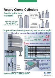

You also want an ePaper? Increase the reach of your titles
YUMPU automatically turns print PDFs into web optimized ePapers that Google loves.
CAT.EUS40-42 C -UK<strong>Modular</strong> F.R.L. <strong>Unit</strong>Integrated digital pressureswitch type is nowavailable.<strong>Series</strong> <strong>AC</strong>
786954132<strong>SMC</strong>Space-saving designThe use of a compact spacer with bracketreduces the total assembly space.New<strong>AC</strong>10<strong>AC</strong>20<strong>AC</strong>25<strong>AC</strong>30<strong>AC</strong>40<strong>AC</strong>40-06<strong>AC</strong>50<strong>AC</strong>55<strong>AC</strong>60ModelOld<strong>AC</strong>1000<strong>AC</strong>2000<strong>AC</strong>2500<strong>AC</strong>3000<strong>AC</strong>4000<strong>AC</strong>4000-06<strong>AC</strong>5000<strong>AC</strong>5500<strong>AC</strong>6000<strong>Modular</strong> F.R.L. <strong>Unit</strong><strong>Series</strong> <strong>AC</strong>Reduction(mm)41414141818181818NewOldReductionImproved installationImproved visibility for lubricant dripwith graduation for lubricant controlGraduationBracket with spacerLever pinRetainerq Attach the component into the fitting of thespacer with bracket.w Lock the lever pin into the retainer.(temporary installation)Spacer withbracketBoltFloat type auto drain withexcellent operability is usedfor compact models (AF10, 20).Drain cock is easy-to-userotary type.Embeddedpressure gaugeis a standard feature.Ozone resistant rubbermaterial (HNBR)Improved relief sensitivitye Tighten the bolt.Integrated digital pressureswitch type is now available.NewKnob coverPrevents careless adjustmentof the pressure setting.Filter RegulatorAW20(K) to 60(K)Mist Separator RegulatorAWM20 to 40Micro Mist Separator RegulatorAWD20 to 40Lock coverKeyhole dia.: ø8Lock (supplied by customer)Part no.AR20P-580ASAR25P-580ASAR30P-580ASAR40P-580ASModel<strong>AC</strong>20/AR20/AR20K/AW20,AW20K/AWM20/AWD20<strong>AC</strong>25/AR25/AR25K<strong>AC</strong>30/AR30/AR30K/AW30,AW30K/AWM30/AWD30<strong>AC</strong>40(-06)/AR40(-06)/AR40K(-06)/AW40(-06)/AW40K(-06)/AWM40/AWD40RegulatorAR20(K) to 60(K)F.R.L. <strong>Unit</strong><strong>AC</strong>20 to 60 (AF+AR+AL)<strong>AC</strong>20A to 60A (AW+AL)<strong>AC</strong>20B to 60B (AF+AR)<strong>AC</strong>20C to 40C (AF+AFM+AR)<strong>AC</strong>20D to 40D (AW+AFM)Features 1
<strong>Series</strong> ConfigurationProductModelPort SizeM5 1/8 1/4 3/8 1/2 3/4 1PageAir Filter + Regulator + LubricatorAF AR AL<strong>AC</strong>10<strong>AC</strong>20<strong>AC</strong>25<strong>AC</strong>30<strong>AC</strong>401<strong>AC</strong>40-60<strong>AC</strong>50<strong>AC</strong>55<strong>AC</strong>60Filter Regulator + LubricatorAWAL<strong>AC</strong>10A<strong>AC</strong>20A<strong>AC</strong>30A<strong>AC</strong>40A7<strong>AC</strong>40A-06<strong>AC</strong>50AAir CombinationAir Filter + RegulatorAF AR<strong>AC</strong>60A<strong>AC</strong>10B<strong>AC</strong>20B<strong>AC</strong>25B<strong>AC</strong>30B<strong>AC</strong>40B11<strong>AC</strong>40B-06<strong>AC</strong>50B<strong>AC</strong>55B<strong>AC</strong>60BAir Filter + Mist Separator + RegulatorAF AFM AR<strong>AC</strong>20C<strong>AC</strong>25C<strong>AC</strong>30C15<strong>AC</strong>40C<strong>AC</strong>40C-06Filter Regulator + Mist SeparatorAWAFM<strong>AC</strong>20D<strong>AC</strong>30D<strong>AC</strong>40D19<strong>AC</strong>40D-06Features 2
<strong>Series</strong> ConfigurationProductModelPort SizeM5 1/8 1/4 3/8 1/2 3/4 1PageAFAF10AF20Air FilterAF30AF40AF40-0629AF50AF60Mist SeparatorAFMAFM20AFM30AFM40AFM40-0635Micro MistSeparatorAFDAFD20AFD30AFD40AFD40-0635ARAR10AR20AR25RegulatorAR30AR40AR40-0641AR50AR60Regulator with BackflowMechanismARKAR20KAR25KAR30KAR40KAR40K-06AR50KAR60K41Features 3
<strong>Series</strong> ConfigurationProductModelPort SizeM5 1/8 1/4 3/8 1/2 3/4 1PageALAL10AL20LubricatorAL30AL40AL40-0651AL50AL60AWAW10Filter RegulatorAW20AW30AW40AW40-0659AW60Filter Regulator withBackflow MechanismAWKAW20KAW30KAW40KAW40K-06AW60K59MistSeparatorRegulatorAWMAWM20AWM30AWM4067Micro MistSeparatorRegulatorAWDAWD20AWD30AWD4067Simple Specials SystemA system designed to respond quicklyand easily to your special ordering needs.Short lead timesThis system enables us to respond to your special needs, such asadditional machining, accessory assembly, or modular unit, anddeliver such special products as quickly as standard products.Repeat ordersOnce we receive a Simple Special part number from your previousorder, we will process the order, manufacture the product, anddeliver it to you.Features 4
Air CombinationAir Filter + Regulator + Lubricator<strong>AC</strong>10 to <strong>AC</strong>60JIS SymbolHow to OrderAir Filter Regulator Lubricator<strong>AC</strong> 3003 DE• Option / Semi-standard: Select one each for a to m.• Option / Attachment / Semi-standard symbol: Enter themalphanumerically.Example) <strong>AC</strong>30-F03DE1-KSTV-136NRNote 3)OptionSemi-standard AttachmentThread typeabcdefghPort sizeFloat typeauto drainPressuregaugeDigitalpressureswitchCheck valvePressureswitchT-interface3-port valve forresidual pressurereleaseSet pressureBowlSymbol-Note 1)NNote 2)F+M5010203040610+-CD+-EGE1E2E3E4+-K+-Note 5)S+-Note 5)T+-V+-Note 6)1+-268C6CWithout auto drainFloat type auto drain (N.C.)Float type auto drain (N.O.)DescriptionMetric thread (M5)RcNPTGM51/81/43/81/23/41Without pressure gaugeSquare embedded type pressure gauge (with limit indicator)Round type pressure gauge (without limit indicator)Round type pressure gauge (with limit indicator)Output: NPN output / Electrical entry: Wiring bottom entryOutput: NPN output / Electrical entry: Wiring top entryOutput: PNP output / Electrical entry: Wiring bottom entryOutput: PNP output / Electrical entry: Wiring top entryWithout attachmentMounting position: AF+AR+K+ALWithout attachmentMounting position: AF+AR+S+ALWithout attachmentMounting position: AF+T+AR+ALWithout attachmentMounting position: AF+AR+AL+V0.05 to 0.85 MPa set0.02 to 0.2 MPa setPolycarbonate bowlMetal bowlNylon bowlMetal bowl with level gaugeWith bowl guardNylon bowl with bowl guardqBody size10 20 25 30 40 50 55 60Note 4)1
Air Combination <strong>Series</strong> <strong>AC</strong>10 to <strong>AC</strong>60<strong>AC</strong>20<strong>AC</strong>40Semi-standardijklmFilterNote 7)Drain portLubricatorLubricantdischarge portExhaustmechanismFlow directionPressure unitSymbolNote 1) Drain guide is NPT1/8 (applicable to the <strong>AC</strong>20)and NPT1/4 (applicable to the <strong>AC</strong>25 to <strong>AC</strong>60).The exhaust port for auto drain comes with aø3/8" One-touch fitting (applicable to the <strong>AC</strong>25 to<strong>AC</strong>60).Note 2) Drain guide is G1/8 (applicable to the <strong>AC</strong>20) andG1/4 (applicable to the <strong>AC</strong>25 to <strong>AC</strong>60).Note 3) Option G is not assembled and is supplied looseat the time of shipment.Note 4) Not available with piping port size 06.Note 5) The bracket position varies depending on the T-interface or the pressure switch mounting.-Note 8)JNote 9)W+-Note 10)3+-N+-R+Without drain cockLubricator with drain cockRelieving typeNon-relieving typeFlow direction: Left to rightFlow direction: Right to leftDescriptionWith drain cockDrain guide 1/8Drain guide 1/4Drain cock with barb fitting: For ø6 x ø4 nylon tube- Name plate and pressure gauge in SI units: MPaNote 11)Z Name plate, caution plate for bowl, and pressure gauge in imperial units (PSI, °F)Note 12)ZA Digital pressure switch: With unit switching functionNote 6) The only difference from the standardspecifications is the adjusting spring for theregulator. It does not restrict the setting of 0.2MPa or more. When the pressure gauge isattached, a 0.2 MPa pressure gauge will be fitted.Note 7) Float type auto drain: The combination between Cor D is not available with the drain port option.Note 8) Without a valve functionNote 9) Metal bowl: The combination of 2 or 8 cannot beselected with W.Note 10) Filter drain port: When choosing with W, thedrain cock of a lubricator will be with barb fittings.Body size10 20 25 30 40 50 55 60Note 13) Note 13) Note 13) Note 13) Note 13) Note 13) Note 13) Note 13)Note 14) Note 14) Note 14) Note 14) Note 14) Note 14) Note 14)Note 11) For thread type: M5 and NPT. This product is foroverseas use only according to the newMeasurement Law. (The SI unit type is providedfor use in Japan.) The digital pressure switch willbe equipped with the unit switching function,setting to PSI initially.Note 12) For options: E1, E2, E3, E4. This product is foroverseas use only according to the newMeasurement Law. (The SI unit is provided foruse in Japan.)Note 13) : For thread type: M5 and NPT onlyNote 14) : Combination available for options: E1, E2,E3, E4.Standard SpecificationsModel<strong>AC</strong>10 <strong>AC</strong>20 <strong>AC</strong>25 <strong>AC</strong>30 <strong>AC</strong>40 <strong>AC</strong>40-06 <strong>AC</strong>50 <strong>AC</strong>55 <strong>AC</strong>60Air filter AF10 AF20 AF30 AF30 AF40 AF40-06 AF50 AF60 AF60Component RegulatorLubricatorAR10AL10M51/16AR20AL201/8, 1/4AR25AL301/4, 3/81/8AR30AL301/4, 3/8AR40AL401/4, 3/8, 1/2AR40-06AL40-063/4AR50AL503/4, 11/4AR50AL601AR60AL601Port sizeNote 1)Pressure gauge port sizeFluidNote 2)Ambient and fluid temperatureProof pressureMax. operating pressureSet pressure rangeRelief pressureNominal filtration ratingRecommended lubricantBowl materialBowl guardRegulator constructionWeight (kg)Air–5 to 60°C (with no freezing)1.5 MPa1.0 MPa0.05 to 0.7 MPa 0.05 to 0.85 MPa— Semi-standardSet pressure + 0.05 MPa Note 3) [at relief flow rate of 0.1 l/min (ANR)]5 µmClass 1 turbine oil (ISO VG32)PolycarbonateStandardRelieving type0.27 0.73 0.91 1.00 1.74 1.95 4.17 4.25 4.34Note 1) Pressure gauge connection threads are not available for F.R.L. units with a square embedded type pressure gauge or with a digital pressure switch (the <strong>AC</strong>20 to <strong>AC</strong>60).Note 2) –5 to 50°C for the products with the digital pressure switchNote 3) Not applicable for <strong>AC</strong>10.2
<strong>Series</strong> <strong>AC</strong>10 to <strong>AC</strong>60Flow Characteristics (Representative values)<strong>AC</strong>100.60.6M5 <strong>AC</strong>20 Rc 1/4<strong>AC</strong>25 Rc 3/80.6Condition: Inlet pressure 0.7 MPaOutlet pressure (MPa)0.50.40.30.20.1Outlet pressure (MPa)0.50.40.30.20.1Outlet pressure (MPa)0.50.40.30.20.10 000 25 50 75 100 125 1500 200 400 600 8000500 1000 1500Flow rate (l/min (ANR)) Flow rate (l/min (ANR)) Flow rate (l/min (ANR))<strong>AC</strong>30 Rc 3/80.6<strong>AC</strong>40 Rc 1/20.6<strong>AC</strong>40-06 Rc 3/40.6Outlet pressure (MPa)0.50.40.30.20.1Outlet pressure (MPa)0.50.40.30.20.1Outlet pressure (MPa)0.50.40.30.20.100500 1000 1500Flow rate (l/min (ANR))001000 2000 3000Flow rate (l/min (ANR))0 0 1000 2000 3000 4000 5000Flow rate (l/min (ANR))<strong>AC</strong>50 Rc 10.6<strong>AC</strong>55 Rc 10.6<strong>AC</strong>60 Rc 10.6Outlet pressure (MPa)0.50.40.30.20.1Outlet pressure (MPa)0.50.40.30.20.1Outlet pressure (MPa)0.50.40.30.20.1002000 4000 6000 8000 10000Flow rate (l/min (ANR))002000 4000 6000 8000 10000Flow rate (l/min (ANR))002000 4000 6000 8000 10000Flow rate (l/min (ANR))Pressure Characteristics (Representative values)<strong>AC</strong>10Outlet pressure (MPa)Outlet pressure (MPa)0.30.250.2Setpoint0.1500 0.2 0.3 0.4 0.5 0.6 0.7 0.8 0.9 1.0Inlet pressure (MPa)<strong>AC</strong>300.250.20.15Setpoint<strong>AC</strong>20Outlet pressure (MPa)Outlet pressure (MPa)0.250.20.150<strong>AC</strong>400.250.20.150 0.2 0.3 0.4 0.5 0.6 0.7 0.8 0.9 1.0Inlet pressure (MPa)Conditions: Inlet pressure 0.7 MPa, Outlet pressure 0.2 MPa, Flow rate 20 l/min (ANR)SetpointSetpoint<strong>AC</strong>25Outlet pressure (MPa)<strong>AC</strong>40-06Outlet pressure (MPa)0.250.20.1500.250.20.15Setpoint0 0.2 0.3 0.4 0.5 0.6 0.7 0.8 0.9 1.0Inlet pressure (MPa)Setpoint00 0.2 0.3 0.4 0.5 0.6 0.7 0.8 0.9 1.0Inlet pressure (MPa)00 0.2 0.3 0.4 0.5 0.6 0.7 0.8 0.9 1.0Inlet pressure (MPa)00 0.2 0.3 0.4 0.5 0.6 0.7 0.8 0.9 1.0Inlet pressure (MPa)3
Air Combination <strong>Series</strong> <strong>AC</strong>10 to <strong>AC</strong>60Pressure Characteristics (Representative values)<strong>AC</strong>50Outlet pressure (MPa)0.250.20.15Setpoint<strong>AC</strong>55Outlet pressure (MPa)0.250.20.15Conditions: Inlet pressure 0.7 MPa, Outlet pressure 0.2 MPa, Flow rate 20 l/min (ANR)Setpoint<strong>AC</strong>60Outlet pressure (MPa)0.250.20.15Setpoint00 0.2 0.3 0.4 0.5 0.6 0.7 0.8 0.9 1.0Inlet pressure (MPa)00 0.2 0.3 0.4 0.5 0.6 0.7 0.8 0.9 1.0Inlet pressure (MPa)00 0.2 0.3 0.4 0.5 0.6 0.7 0.8 0.9 1.0Inlet pressure (MPa)Specific Product PrecautionsCautionMounting and Adjustment1. A knob cover is available to prevent careless operation of theknob. Refer to “Features 1” for details.WarningPiping1. When mounting a check valve, make sure the arrow (IN side)points in the correct direction of air flow.CautionAir Supply1. Use an air filter with 5 µm or less filtration rating on the inletside of the valve to avoid any damage to the seat caused bydust when mounting a 3-port valve for residual pressurerelease on the inlet side.WarningSelection1. Float type auto drainOperate under the following conditions to avoid malfunction.• Operating compressor: 0.75 kW (100 l/min (ANR)) or more.When using 2 or more auto drains, multiply the value aboveby the number of auto drains to find the capacity of thecompressors you will need.For example, when using 2 auto drains, 1.5 kW (200 l/min(ANR)) of compressor capacity is required.• Operating pressure: 0.1 MPa or more.• Operating pressure for AD17/27: 0.1 MPa or more.• Operating pressure for AD37/47: 0.15 MPa or more.2. Use a regulator or filter regulator with backflow mechanismwhen mounting a 3-port valve for residual pressure release onthe IN side to ensure the release of the residual pressure.Otherwise, residual pressure will not be fully released.Caution1. When releasing air at the intermediate position using a T-interface on the inlet side of the lubricator, lubricant may backflow. Therefore, releasing air that does not contain traces oflubricant is not possible.To release air that does not contain traces of lubricant, use acheck valve (the AKM series) on the inlet side of the lubricatorto prevent a back flow of the lubricant.2. Mounting a 3-port valve for residual pressure release on the INside of the lubricator can cause lubricant to back flow. Takemeasures to prevent lubricant from splashing by installing afilter on the EXH port.3. An F.R.L. unit shipped from the plant has its model numberlabeled. However, components that are combined togetherduring the distribution process do not have a label on them.4
O<strong>Series</strong> <strong>AC</strong>10 to <strong>AC</strong>60Dimensions<strong>AC</strong>10, <strong>AC</strong>20P2(Pressure gauge port size)<strong>AC</strong>25 to <strong>AC</strong>60P2(Pressure gauge port size)AAJMFNR2JMFNR2KQ1VINCOUTKQ1VINCOUTOUTQ1Q2R1OUTQ1R1B2-P1(Port size)Min. clearancefor maintenanceGUDrainAirFilterSRegulator Lubricator2-P1(Port size)Min. clearancefor maintenanceGEUDrainAir FilterSRegulator LubricatorLApplicable model <strong>AC</strong>20 to <strong>AC</strong>60 <strong>AC</strong>10 to <strong>AC</strong>60Option Square embedded type pressure gauge Digital pressure switch Round type pressure gaugeJJJDimensionsHCentre ofpipingHCentre ofpipingHCentre ofpipingApplicable model <strong>AC</strong>10, <strong>AC</strong>20 <strong>AC</strong>20 <strong>AC</strong>25 to <strong>AC</strong>60With auto drain (N.C.) Metal bowl With drain guide With auto drain (N.O./N.C.) Metal bowl Metal bowl with level gaugeOptional/Semi-standardspecificationsWith drain guideDrain cock with barb fittingDimensionsOSBM5BB1/8Width across flats 14N.O.: BlackN.C.: Grayø10 One-touchfittingSBBBB1/4Width across flats 17BBarb fittingApplicable tubing: T0604Model<strong>AC</strong>10<strong>AC</strong>20<strong>AC</strong>25<strong>AC</strong>30<strong>AC</strong>40<strong>AC</strong>40-06<strong>AC</strong>50<strong>AC</strong>55<strong>AC</strong>60Standard specificationsP1 P2 A B C E F G JM51/8, 1/41/4, 3/81/4, 3/81/4, 3/8, 1/23/43/4, 1111/161/81/81/81/41/41/41/41/48712616716722023528229229785123153153187187264279280263638384038434546——303038384547.547.52841.5555572.577.5939898356080801101101101101101328.527.529.5343443.543.543.5K0Note) 203.53.533.33.33.3Square typepressure gaugeH—2828282828282828J—29.528.530.5353544.544.544.5Optional specificationsDigitalpressure gaugeH—27.827.827.827.827.827.827.827.8J—4039414545555555Round typepressure gaugeHø26ø37.5ø37.5ø37.5ø42.5ø42.5ø42.5ø42.5ø42.5J266564667474848484Optional specificationsSemi-standard specificationsModelBracket mount With auto drain With barb fitting With drain guide Metal bowlMetal bowl withlevel gaugeM N Q1 Q2 R1 R2 S U V B B B B B<strong>AC</strong>10<strong>AC</strong>20<strong>AC</strong>25<strong>AC</strong>30<strong>AC</strong>40<strong>AC</strong>40-06<strong>AC</strong>50<strong>AC</strong>55<strong>AC</strong>6025304141505070707031435757758096961012024353540405050502733———————4.55.57799111111ø4.5ø5.5ø7ø7ø9ø9ø11ø11ø11712141418182020202.83.24444.66.46.46.424.52941414848606060104141194194226226303318319——161161195195272287288—12716016019419427128628785123166166200200276292293——186186220220296312313Note) For the <strong>AC</strong>20 only, the position of the pressure gauge is above the centre of the piping.5
Air CombinationFilter Regulator + Lubricator<strong>AC</strong>10A to <strong>AC</strong>60AJIS SymbolHow to OrderFilter RegulatorLubricator<strong>AC</strong>30 A 03 DE• Option / Semi-standard: Select one each for a to l.• Option / Attachment / Semi-standard symbol: Enter themalphanumerically.Example) <strong>AC</strong>30A-F03DE1-KSV-136NRNote 3)OptionSemi-standard AttachmentThread typeabcdefghPort sizeFloat typeauto drainPressuregaugeDigitalpressureswitchCheck valvePressureswitch3-port valve forresidual pressurereleaseSet pressureBowlFilter regulatorNote 7)Drain portSymbol-Note 1)NNote 2)F+M5010203040610+-CD+-EGE1E2E3E4+-K+-Note 5)S+-V+-Note 6)1+-268C6C+-Note 8)JNote 9)WWithout auto drainFloat type auto drain (N.C.)Float type auto drain (N.O.)DescriptionMetric thread (M5)RcNPTGM51/81/43/81/23/41Without pressure gaugeSquare embedded type pressure gauge (with limit indicator)Round type pressure gauge (without limit indicator)Round type pressure gauge (with limit indicator)Output: NPN output / Electrical entry: Wiring bottom entryOutput: NPN output / Electrical entry: Wiring top entryOutput: PNP output / Electrical entry: Wiring bottom entryOutput: PNP output / Electrical entry: Wiring top entryWithout attachmentMounting position: AW+K+ALWithout attachmentMounting position: AW+S+ALWithout attachmentMounting position: AW+AL+V0.05 to 0.85 MPa set0.02 to 0.2 MPa setPolycarbonate bowlMetal bowlNylon bowlMetal bowl with level gaugeWith bowl guardNylon bowl with bowl guardWith drain cockDrain guide 1/8Drain guide 1/4Drain cock with barb fitting: For ø6 x ø4 nylon tubeBody size10 20 30 40 50 60Note 4)7
Air Combination <strong>Series</strong> <strong>AC</strong>10A to <strong>AC</strong>60A<strong>AC</strong>20A<strong>AC</strong>40ASemi-standard+++Standard SpecificationsComponentPort sizeModelNote 1)Pressure gauge port sizeFluidNote 2)Ambient and fluid temperatureProof pressureMaximum operating pressureSet pressure rangeRelief pressureNominal filtration ratingRecommended lubricantBowl materialijklBowl guardRegulator constructionWeight (kg)LubricatorLubricantdischarge portExhaustmechanismFlow directionPressure unitSymbol-3-N-R-Note 10)ZNote 11)ZANote 1) Drain guide is NPT1/8 (applicable to the <strong>AC</strong>20A)and NPT1/4 (applicable to the <strong>AC</strong>30A to <strong>AC</strong>60A).The exhaust port for auto drain comes with aø3/8" One-touch fitting (applicable to the <strong>AC</strong>30Ato <strong>AC</strong>60A).Note 2) Drain guide is G1/8 (applicable to the <strong>AC</strong>20A)and G1/4 (applicable to the <strong>AC</strong>30A to <strong>AC</strong>60A).Note 3) Option G is not assembled and is supplied looseat the time of shipment.Note 4) Not available with piping port size 06.Note 5) The bracket position varies depending on thepressure switch mounting.Filter regulatorLubricatorWithout drain cockLubricator with drain cockRelieving typeNon-relieving typeFlow direction: Left to rightFlow direction: Right to left<strong>AC</strong>10AAW10AL10M51/160.05 to 0.7 MPa—0.20DescriptionName plate and pressure gauge in SI units: MPaName plate, caution plate for bowl, and pressure gauge in imperial units (PSI, °F)Digital pressure switch: With unit switching functionNote 6) The only difference from the standardspecifications is the adjusting spring for theregulator. It does not restrict the setting of 0.2MPa or more. When the pressure gauge isattached, a 0.2 MPa pressure gauge will be fitted.Note 7) Float type auto drain: The combination between Cor D is not available with the drain port options.Note 8) Without a valve functionNote 9) Metal bowl: The combination of 2 or 8 cannot beselected with W.Note 10) For thread type: M5 and NPT. This product is foroverseas use only according to the newMeasurement Law. (The SI unit type is providedfor use in Japan.) The digital pressure switch willbe equipped with the unit switching function,setting to PSI initially.<strong>AC</strong>20AAW20AL201/8, 1/4Note 1) Pressure gauge connection threads are not available for F.R.L. units with a square embedded type pressure gauge or with a digital pressure switch (the <strong>AC</strong>20A to <strong>AC</strong>60A).Note 2) –5 to 50°C for the products with the digital pressure switchNote 3) Not applicable for <strong>AC</strong>10A.Air–5 to 60°C (with no freezing)1.5 MPa1.0 MPaSet pressure + 0.05 MPa Note 3) [at relief flow rate of 0.1 l/min (ANR)]Semi-standard0.59<strong>AC</strong>30AAW30AL301/4, 3/8<strong>AC</strong>40AAW40AL401/4, 3/8, 1/21/8 1/45 µm0.05 to 0.85 MPaClass 1 turbine oil (ISO VG32)PolycarbonateRelieving typeBody size10 20 30 40 50 60Note 12) Note 12) Note 12) Note 12) Note 12) Note 12)Note 11) For options: E1, E2, E3, E4. This product is foroverseas use only according to the newMeasurement Law. (The SI unit is provided foruse in Japan.)Note 12) : For thread type: M5 and NPT onlyNote 13) : Combination available for options: E1, E2,E3, E4.<strong>AC</strong>40A-06AW40-06AL40-063/4StandardNote 13) Note 13) Note 13) Note 13) Note 13)<strong>AC</strong>50AAW60AL503/4, 1<strong>AC</strong>60AAW60AL600.75 1.41 1.46 3.33 3.4018
OUTO<strong>Series</strong> <strong>AC</strong>10A to <strong>AC</strong>60ADimensions<strong>AC</strong>10A, <strong>AC</strong>20AJMP2(Pressure gauge port size)AF<strong>AC</strong>30A to <strong>AC</strong>60AJM2-P1(Port size)P2(Pressure gauge port size)AF2-P1(Port size)R2R2KQ1VCINOUTKQ1VINOUTQ1Q2CBOUTQ1BR1USR1USMin. clearancefor maintenanceGDrainFilterRegulatorLubricatorMin. clearancefor maintenanceGEDrainFilterRegulatorLubricatorApplicable model <strong>AC</strong>20A to <strong>AC</strong>60A <strong>AC</strong>10A to <strong>AC</strong>60AOption Square embedded type pressure gauge Digital pressure switch Round type pressure gaugeJJJDimensionsHCentre ofpipingHCentre ofpipingHCentre ofpipingApplicable model <strong>AC</strong>10A, <strong>AC</strong>20A <strong>AC</strong>20A <strong>AC</strong>30A to <strong>AC</strong>60AWith auto drain (N.C.) Metal bowl With drain guide With auto drain (N.O./N.C.) Metal bowl Metal bowl with level gauge With drain guideOptional/Semi-standardspecificationsDrain cock with barb fittingDimensionsOSBM5BB1/8Width across flats 14N.O.: BlackN.C.: Grayø10 One-touchfittingSBBBB1/4Width across flats 17BBarb fittingApplicable tubing: T0604Model<strong>AC</strong>10A<strong>AC</strong>20A<strong>AC</strong>30A<strong>AC</strong>40A<strong>AC</strong>40A-06<strong>AC</strong>50A<strong>AC</strong>60AStandard specificationsP1 P2 A B Note) C E F G JM5 1/161/8, 1/4 1/81/4, 3/8 1/81/4, 3/8, 1/2 1/43/4 1/43/4, 1 1/41 1/456831101451551911961081602012392424094094873869293175175——303838——2841.55572.577.59898356080110110110110132629.537.537.543.543.5K053.51.51.23.23.2Square typepressure gaugeH—282828282828J—2730.538.538.544.544.5Optional specificationsDigitalpressure gaugeH—27.827.827.827.827.827.8J—37.541494961.561.5Round typepressure gaugeHø26ø37.5ø37.5ø42.5ø42.5ø42.5ø42.5J26636676768484Optional specificationsSemi-standard specificationsModelBracket mount With auto drain With barb fitting With drain guide Metal bowlM Q1 Q2 R1 R2 S U V BBBB<strong>AC</strong>10A 25 20 27 4.5 ø4.5 7 2.8 24.5 125——107<strong>AC</strong>20A 30 24 33 5.5 ø5.5 12 3.2 29 177—164160<strong>AC</strong>30A 41 35 — 7 ø7 14 4 41 242209208214<strong>AC</strong>40A 50 40 — 9 ø9 18 4 48 278247246252<strong>AC</strong>40A-06 50 40 — 9 ø9 18 4.6 48 282251249255<strong>AC</strong>50A 70 50 — 11 ø11 20 6.4 60 448417416422<strong>AC</strong>60A 70 50 — 11 ø11 20 6.4 60 448417416422Note) The total length of B dimension is the length when the filter regulator handle is unlocked.9Metal bowl withlevel gaugeB——234272275442442
Air CombinationAir Filter + Regulator<strong>AC</strong>10B to <strong>AC</strong>60BJIS SymbolHow to OrderAir FilterRegulator<strong>AC</strong>30 B 03 DE• Option / Semi-standard: Select one each for a to j.• Option / Attachment / Semi-standard symbol: Enter themalphanumerically.Example) <strong>AC</strong>30B-F03DE1-SV-16NRNote 3)Semi-standardAttachmentOptionThread typeabcdefgPort sizeFloat typeauto drainPressuregaugeDigitalpressureswitchPressureswitchT-interface3-port valve forresidual pressurereleaseSet pressureBowlFilterNote 7)Drain portSymbol-Note 1)NNote 2)F+M5010203040610+-CD+-EGE1E2E3E4+-Note 4)SNote 4)T+-VNote 5)V1+-Note 6)1+-268C6C+-Note 8)JNote 9)WWithout auto drainFloat type auto drain (N.C.)Float type auto drain (N.O.)DescriptionMetric thread (M5)RcNPTGM51/81/43/81/23/41Without pressure gaugeSquare embedded type pressure gauge (with limit indicator)Round type pressure gauge (without limit indicator)Round type pressure gauge (with limit indicator)Output: NPN output / Electrical entry: Wiring bottom entryOutput: NPN output / Electrical entry: Wiring top entryOutput: PNP output / Electrical entry: Wiring bottom entryOutput: PNP output / Electrical entry: Wiring top entryWithout attachmentMounting position: AF+S+ARMounting position: AF+T+ARWithout attachmentMounting position: AF+AR+VMounting position: V+AF+ARK0.05 to 0.85 MPa set0.02 to 0.2 MPa setPolycarbonate bowlMetal bowlNylon bowlMetal bowl with level gaugeWith bowl guardNylon bowl with bowl guardWith drain cockDrain guide 1/8Drain guide 1/4Drain cock with barb fitting: For ø6 x ø4 nylon tubeBody size10 20 25 30 40 50 55 6011
Air Combination <strong>Series</strong> <strong>AC</strong>10B to <strong>AC</strong>60B<strong>AC</strong>20B<strong>AC</strong>40BSemi-standardhijExhaustmechanismFlow directionPressure unitSymbol-NNote 1) Drain guide is NPT1/8 (applicable to the <strong>AC</strong>20B)and NPT1/4 (applicable to the <strong>AC</strong>25B to <strong>AC</strong>60B).The exhaust port for auto drain comes with aø3/8" One-touch fitting (applicable to the <strong>AC</strong>25Bto <strong>AC</strong>60B).Note 2) Drain guide is G1/8 (applicable to the <strong>AC</strong>20B)and G1/4 (applicable to the <strong>AC</strong>25B to <strong>AC</strong>60B).Note 3) Option G is not assembled and is supplied looseat the time of shipment.Note 4) The bracket position varies depending on the T-interface or the pressure switch mounting.+-R+Relieving typeNon-relieving typeFlow direction: Left to rightFlow direction: Right to leftDescription- Name plate and pressure gauge in SI units: MPaNote 10)Z Name plate, caution plate for bowl, and pressure gauge in imperial units (PSI, °F)Note 11)ZA Digital pressure switch: With unit switching functionNote 5) In this configuration the regulator is equipped witha back from mechanism. Additionally, for safetypurposes, please check that the pressure on theoutlet side is at atmospheric pressure after thepressure on the outlet side is exhausted, by usinga pressure gauge, etc.Note 6) The only difference from the standardspecifications is the adjusting spring for theregulator. It does not restrict the setting of 0.2MPa or more. When the pressure gauge isattached, a 0.2 MPa pressure gauge will be fitted.Note 7) Float type auto drain: The combination between Cor D is not available with the drain port options.Note 8) Without a valve functionBody size10 20 25 30 40 50 55 60Note 12) Note 12) Note 12) Note 12) Note 12) Note 12) Note 12) Note 12)Note 13) Note 13) Note 13) Note 13) Note 13) Note 13) Note 13)Note 9) Metal bowl: The combination of 2 or 8 cannot beselected with W.Note 10) For thread type: M5 and NPT. This product is foroverseas use only according to the newMeasurement Law. (The SI unit type is providedfor use in Japan.) The digital pressure switch willbe equipped with the unit switching function,setting to PSI initially.Note 11) For options: E1, E2, E3, E4. This product is foroverseas use only according to the newMeasurement Law. (The SI unit is provided foruse in Japan.)Note 12) : For thread type: M5 and NPT onlyNote 13) : Combination available for options: E1, E2,E3, E4.Standard SpecificationsComponentPort sizeModelNote 1)Pressure gauge port sizeFluidNote 2)Ambient and fluid temperatureProof pressureMaximum operating pressureSet pressure rangeRelief pressureNominal filtration ratingBowl materialBowl guardRegulator constructionWeight (kg)Air filterRegulator<strong>AC</strong>10BAF10AR10M51/160.05 to 0.7 MPa—0.16<strong>AC</strong>20BAF20AR201/8, 1/4Semi-standard0.51<strong>AC</strong>25BAF30AR251/4, 3/8<strong>AC</strong>30BAF30AR301/4, 3/8<strong>AC</strong>40BAF40AR401/4, 3/8, 1/2<strong>AC</strong>40B-06AF40-06AR40-063/4<strong>AC</strong>50BAF50AR503/4, 11/8 1/4Note 1) Pressure gauge connection threads are not available for F.R.L. units with a square embedded type pressure gauge or with a digital pressure switch (the <strong>AC</strong>10B to <strong>AC</strong>60B).Note 2) –5 to 50°C for the products with the digital pressure switchNote 3) Not applicable for <strong>AC</strong>10B.Air–5 to 60°C (with no freezing)1.5 MPa1.0 MPa0.05 to 0.85 MPaSet pressure + 0.05 MPa Note 3) [at relief flow rate of 0.1 l/min (ANR)]5 µmPolycarbonateRelieving typeStandard<strong>AC</strong>55BAF60AR501<strong>AC</strong>60BAF60AR6010.55 0.63 1.12 1.16 2.44 2.45 2.5412
O<strong>Series</strong> <strong>AC</strong>10B to <strong>AC</strong>60BDimensions<strong>AC</strong>10B, <strong>AC</strong>20BJ MFAR2P2(Pressure gauge port size)<strong>AC</strong>25B to <strong>AC</strong>60BJMP2(Pressure gauge port size)AFR2KQ1VINCOUTKQ1VINCOUTQ1R12-P1(Port size)USBMin. clearancefor maintenanceBQ1Q22-P1(Port size)UR1SMin. clearancefor maintenanceGDrainAir FilterRegulatorGEDrainAir FilterRegulatorApplicable model <strong>AC</strong>20B to <strong>AC</strong>60B <strong>AC</strong>10B to <strong>AC</strong>60BOption Square embedded type pressure gauge Digital pressure switch Round type pressure gaugeJJJDimensionsHCentre ofpipingHCentre ofpipingHCentre ofpipingApplicable model <strong>AC</strong>10B, <strong>AC</strong>20B <strong>AC</strong>20B <strong>AC</strong>25B to <strong>AC</strong>60BWith auto drain (N.C.) Metal bowl With drain guide With auto drain (N.O./N.C.) Metal bowl Metal bowl with level gauge With drain guideOptional/Semi-standardspecificationsDrain cock with barb fittingDimensionsOSBM5BB1/8Width across flats 14ø10 One-touchfittingN.O.: BlackN.C.: GraySBBBB1/4Width across flats 17BBarb fittingApplicable tubing: T0604Model<strong>AC</strong>10B<strong>AC</strong>20B<strong>AC</strong>25B<strong>AC</strong>30B<strong>AC</strong>40B<strong>AC</strong>40B-06<strong>AC</strong>50B<strong>AC</strong>55B<strong>AC</strong>60BStandard specificationsP1 P2 A B C E F G JM5 1/161/8, 1/4 1/81/4, 3/8 1/81/4, 3/8 1/81/4, 3/8, 1/2 1/43/4 1/43/4, 1 1/41 1/41 1/45683110110145155186191196711141431461831852632772801126.528313636434346——303038384547.547.52841.5555572.577.59398982540505075752020201328.527.529.5343443.543.543.5K0Note)203.53.533.33.33.3Square typepressure gaugeH—2828282828282828J—29.528.530.5353544.544.544.5Optional specificationsDigitalpressure gaugeH—27.827.827.827.827.827.827.827.8J—4039414545555555Round typepressure gaugeHø26ø37.5ø37.5ø37.5ø42.5ø42.5ø42.5ø42.5ø42.5J266564667474848484Optional specificationsSemi-standard specificationsModelBracket mount With auto drain With barb fitting With drain guide Metal bowlM Q1 Q2 R1 R2 S U V BBBB<strong>AC</strong>10B 25 20 27 4.5 ø4.5 7 2.8 24.5 89——70<strong>AC</strong>20B 30 24 33 5.5 ø5.5 12 3.2 29 132—118114<strong>AC</strong>25B 41 35 — 7 ø7 14 4 41 184151150156<strong>AC</strong>30B 41 35 — 7 ø7 14 4 41 187154153159<strong>AC</strong>40B 50 40 — 9 ø9 18 4 48 222191190196<strong>AC</strong>40B-06 50 40 — 9 ø9 18 4.6 48 224193192198<strong>AC</strong>50B 70 50 — 11 ø11 20 6.4 60 303271270277<strong>AC</strong>55B 70 50 — 11 ø11 20 6.4 60 316285284290<strong>AC</strong>60B 70 50 — 11 ø11 20 6.4 60 319288287293Note) For the <strong>AC</strong>20B only, the position of the pressure gauge is above the centre of the piping.13Metal bowl withlevel gaugeB——176179216218297310313
Air CombinationAir Filter + Mist Separator + Regulator<strong>AC</strong>20C to <strong>AC</strong>40CJIS SymbolHow to OrderAir FilterMist Separator Regulator<strong>AC</strong>30 C 03 DE• Option / Semi-standard: Select one each for a to j.• Option / Attachment / Semi-standard symbol: Enter themalphanumerically.Example) <strong>AC</strong>30C-F03DE1-SV-16NRSymbolDescription20Body size25 30 4015Note 3)Semi-standard AttachmentOptionThread typeabcdefghiPort sizeFloat typeauto drainPressuregaugeDigitalpressureswitchPressureswitchT-interface3-port valve forresidual pressurereleaseSet pressureBowlFilterNote 7)Drain portExhaustmechanismFlow direction-Note 1)NNote 2)F+0102030406+-CD+-EGE1E2E3E4+-Note 4)SNote 4)T+-VNote 5)V1+-Note 6)1+-268C6C+-Note 8)JWithNote 9)W+-N+-RWithout auto drainFloat type auto drain (N.C.)Float type auto drain (N.O.)RcNPTG1/81/43/81/23/4Without pressure gaugeSquare embedded type pressure gauge (with limit indicator)Round type pressure gauge (with limit indicator)Output: NPN output / Electrical entry: Wiring bottom entryOutput: NPN output / Electrical entry: Wiring top entryOutput: PNP output / Electrical entry: Wiring bottom entryOutput: PNP output / Electrical entry: Wiring top entryWithout attachmentMounting position: AF+AFM+S+ARMounting position: AF+AFM+T+ARWithout attachmentMounting position: AF+AFM+AR+VMounting position: V+AF+AFM+ARK0.05 to 0.85 MPa set0.02 to 0.2 MPa setPolycarbonate bowlMetal bowlNylon bowlMetal bowl with level gaugeWith bowl guardNylon bowl with bowl guarddrain cockDrain guide 1/8Drain guide 1/4Drain cock with barb fitting: For ø6 x ø4 nylon tubeRelieving typeNon-relieving typeFlow direction: Left to rightFlow direction: Right to left
Air Combination <strong>Series</strong> <strong>AC</strong>20C to <strong>AC</strong>40C<strong>AC</strong>20C<strong>AC</strong>40CSymbolDescription20Body size25 30 40SemistandardComponentPort sizeModelNote 1)Pressure gauge port sizeFluidNote 2)Ambient and fluid temperatureProof pressureMaximum operating pressureMinimum operating pressureSet pressure rangeRelief pressureNominal filtration ratingOutlet side oil mist concentrationNote 3)Rated flow (l/min (ANR))Bowl materialjBowl guardRegulator constructionWeight (kg)Pressure unitNote 1) Drain guide is NPT1/8 (applicable to the <strong>AC</strong>20C)and NPT1/4 (applicable to the <strong>AC</strong>30C to <strong>AC</strong>40C).The exhaust port for auto drain comes with ø3/8"One-touch fitting (applicable to the <strong>AC</strong>30C to<strong>AC</strong>40C).Note 2) Drain guide is G1/8 (applicable to the <strong>AC</strong>20C)and G1/4 (applicable to the <strong>AC</strong>30C to <strong>AC</strong>40C).Note 3) Option G is not assembled and is supplied looseat the time of shipment.Note 4) The bracket position varies depending on the T-interface or the pressure switch mounting.Standard SpecificationsAir filterRegulatorLubricator- Name plate and pressure gauge in SI units: MPaNote 10)Z Name plate, caution plate for bowl, and pressure gauge in imperial units (PSI, °F)Note 11)ZA Digital pressure switch: With unit switching functionNote 5) In this configuration the regulator is equipped witha backflow mechanism. Additionally, for safetypurposes, please check that the pressure on theoutlet side is at atmospheric pressure after thepressure on the outlet side is exhausted, by usinga pressure gauge, etc.Note 6) The only difference from the standardspecifications is the adjusting spring for theregulator. It does not restrict the setting of 0.2MPa or more. When the pressure gauge isattached, a 0.2 MPa pressure gauge will be fitted.Note 7) Float type auto drain: The combination between Cor D is not available with the drain port options.Note 8) Without a valve function<strong>AC</strong>20CAF20AFM20AR201/8, 1/4200Semi-standard0.74<strong>AC</strong>25CAF30AFM30AR251/4, 3/8Air–5 to 60°C (with no freezing)1.5 MPa1.0 MPa0.05 MPa0.05 to 0.85 MPaSet pressure + 0.05 MPa Note 3) [at relief flow rate of 0.1 l/min (ANR)]AF: 5 µm, AFM: 0.3 µm (95% filtered particle size)Max. 1.0 mg/m 3 Note 4) Note 5)(ANR) (≈ 0.8 ppm)4500.88<strong>AC</strong>30CAF30AFM30AR301/4, 3/8Polycarbonate450Relieving type0.95StandardNote 12) Note 12) Note 12) Note 12)Note 13) Note 13) Note 13) Note 13)Note 9) Metal bowl: The combination of 2 or 8 cannot beselected with W.Note 10) For thread type: NPT. This product is foroverseas use only according to the newMeasurement Law. (The SI unit type is providedfor use in Japan.) The digital pressure switch willbe equipped with the unit switching function,setting to PSI initially.Note 11) For options: E1, E2, E3, E4. This product is foroverseas use only according to the newMeasurement Law. (The SI unit is provided foruse in Japan.)Note 12) : For thread type: NPT onlyNote 13) : Combination available for options: E1, E2,E3, E4.<strong>AC</strong>40CAF40AFM40AR401/4, 3/8, 1/21/8 1/411001.76<strong>AC</strong>40C-06AF40-06AFM40-06AR40-06Note 1) Pressure gauge connection threads are not available for F.R.L. units with a square embedded type pressure gauge or with a digital pressure switch (the <strong>AC</strong>20C to <strong>AC</strong>40C).Note 2) –5 to 50°C for the products with the digital pressure switch.Note 3) Conditions: Mist separator inlet pressure: 0.7 MPa; The rated flow varies depending on the inlet pressure. Keep the air flow within the rated flow to prevent an outflow oflubricant to the outlet side.Note 4) When the compressor oil mist discharge concentration is 30 mg/m 3 (ANR).Note 5) Bowl O-ring and other O-rings are slightly lubricated.3/411001.8316
O<strong>Series</strong> <strong>AC</strong>20C to <strong>AC</strong>40CDimensions<strong>AC</strong>20C<strong>AC</strong>25C to <strong>AC</strong>40C-06JMFP2(Pressure gauge port size)ANR2JMFANP2(Pressure gauge port size)R2KQ1 Q1Q2 VCIN OUT INOUTKQ1VCQ12-P1(Port size)UR1SB2-P1(Port size)UR1SBMin. clearancefor maintenanceGDrainAir FilterDrainMist RegulatorSeparatorMin. clearancefor maintenanceGEDrainAir FilterDrainMistSeparatorRegulatorApplicable modelOptionSquare embedded type pressure gaugeJ<strong>AC</strong>20C to <strong>AC</strong>40C-06Digital pressure switchJRound type pressure gaugeJDimensionsHCentre ofpipingHCentre ofpipingHCentre ofpipingApplicable model <strong>AC</strong>20C <strong>AC</strong>25C to <strong>AC</strong>40C-06With auto drain (N.C.) Metal bowl With drain guide With auto drain (N.O./N.C.) Metal bowl Metal bowl with level gauge With drain guideOptional/Semi-standardspecificationsDrain cock with barb fittingDimensionsOSBM5BB1/8Width across flats 14N.O.: BlackN.C.: Grayø10 One-touchfittingSBBBB1/4Width across flats 17BBarb fittingApplicable tubing: T0604Model<strong>AC</strong>20C<strong>AC</strong>25C<strong>AC</strong>30C<strong>AC</strong>40C<strong>AC</strong>40C-06Standard specificationsP1 P2 A B C E F G J1/8, 1/4 1/81/4, 3/8 1/81/4, 3/8 1/81/4, 3/8, 1/2 1/43/4 1/412616716722023511414314618318526.528313636—3030383841.5555572.577.5455050757528.527.529.53434KNote)203.53.53Square typepressure gaugeH2828282828J29.528.530.53535Optional specificationsDigitalpressure gaugeH27.827.827.827.827.8J4039414545Round typepressure gaugeHø37.5ø37.5ø37.5ø42.5ø42.5J6564667474Optional specificationsSemi-standard specificationsModelBracket mount With auto drain With barb fitting With drain guide Metal bowlMetal bowl withlevel gaugeM N Q1 Q2 R1 R2 S U V B B B B B<strong>AC</strong>20C<strong>AC</strong>25C<strong>AC</strong>30C<strong>AC</strong>40C<strong>AC</strong>40C-0630414150504357577580243535404033————5.57799ø5.5ø7ø7ø9ø912141418183.24444.62941414848132184187222224—151154191193118150153190192114156159196198—176179216218Note) For the <strong>AC</strong>20C only, the position of the pressure gauge is above the centre of the piping.17
Air CombinationFilter Regulator + Mist Separator<strong>AC</strong>20D to <strong>AC</strong>40DJIS SymbolHow to OrderFilter RegulatorMist Separator<strong>AC</strong>30 D 03 DE• Option / Semi-standard: Select one each for a to j.• Option / Attachment / Semi-standard symbol: Enter themalphanumerically.Example) <strong>AC</strong>30D-F03DE1-SV-16NRSymbolDescription20Body size30 40Note 3)OptionSemi-standard AttachmentThread typeabcdefPort sizeFloat typeauto drainPressuregaugeDigitalpressureswitchPressureswitch3-port valve forresidual pressurereleaseWithFilter regulatorg Mist separatorNote 7)Drain porthiSet pressureBowlExhaustmechanismFlow direction-Note 1)NNote 2)F+0102030406+-CD+-EGE1E2E3E4+-Note 4)S+-VNote 5)V1+-Note 6)1+-268C6C+-Note 8)JNote 9)W+-N+-RWithout auto drainFloat type auto drain (N.C.)Float type auto drain (N.O.)RcNPTG1/81/43/81/23/4Without pressure gaugeSquare embedded type pressure gauge (with limit indicator)Round type pressure gauge (with limit indicator)Output: NPN output / Electrical entry: Wiring bottom entryOutput: NPN output / Electrical entry: Wiring top entryOutput: PNP output / Electrical entry: Wiring bottom entryOutput: PNP output / Electrical entry: Wiring top entryWithout attachmentMounting position: AW+S+AFMWithout attachmentMounting position: AW+AFM+VMounting position: V+AWK+AFM0.05 to 0.85 MPa set0.02 to 0.2 MPa setPolycarbonate bowlMetal bowlNylon bowlMetal bowl with level gaugeWith bowl guardNylon bowl with bowl guarddrain cockDrain guide 1/8Drain guide 1/4Drain cock with barb fitting: For ø6 x ø4 nylon tubeRelieving typeNon-relieving typeFlow direction: Left to rightFlow direction: Right to left19
Air Combination <strong>Series</strong> <strong>AC</strong>20D to <strong>AC</strong>40D<strong>AC</strong>20D<strong>AC</strong>40DSymbolDescription20Body size30 40SemistandardjPressure unitNote 1) Drain guide is NPT1/8 (applicable to the <strong>AC</strong>20D)and NPT1/4 (applicable to the <strong>AC</strong>30D to <strong>AC</strong>40D).The exhaust port for auto drain comes with ø3/8"a One-touch fitting (applicable to the <strong>AC</strong>30D to<strong>AC</strong>40D).Note 2) Drain guide is G1/8 (applicable to the <strong>AC</strong>20D)and G1/4 (applicable to the <strong>AC</strong>30D to <strong>AC</strong>40D).Note 3) Option G is not assembled and is supplied looseat the time of shipment.Note 4) The bracket position varies depending on thepressure switch mounting.Standard SpecificationsComponentPort sizeModelNote 1)Pressure gauge port sizeFluidNote 2)Ambient and fluid temperatureProof pressureMaximum operating pressureMinimum operating pressureSet pressure rangeRelief pressureNominal filtration ratingNote 3)Rated flow (l/min (ANR))Outlet side oil mist concentrationBowl materialBowl guardRegulator constructionWeight (kg)Filter regulatorMist separator- Name plate and pressure gauge in SI units: MPaNote 10)Z Name plate, caution plate for bowl, and pressure gauge in imperial units (PSI, °F)Note 11)ZA Digital pressure switch: With unit switching functionNote 5) In this configuration the regulator is equipped witha backflow mechanism. Additionally, for safetypurposes, please check that the pressure on theoutlet side is at atmospheric pressure after thepressure on the outlet side is exhausted, by usinga pressure gauge, etc.Note 6) The only difference from the standardspecifications is the adjusting spring for theregulator. It does not restrict the setting of 0.2MPaor more. When the pressure gauge is attached, a0.2 MPa pressure gauge will be fitted.Note 7) Float type auto drain: The combination between Cor D is not available with the drain port options.Note 8) Without a valve function<strong>AC</strong>20DAW20AFM201/8, 1/4150Semi-standard0.57<strong>AC</strong>30DAW30AFM301/4, 3/8Air–5 to 60°C (with no freezing)1.5 MPa1.0 MPa0.05 MPa0.05 to 0.85 MPaSet pressure + 0.05 MPa Note 3) [at relief flow rate of 0.1 l/min (ANR)]AF: 5 µm, AFM: 0.3 µm (95% filtered particle size)330Max. 1.0 mg/m 3 Note 4) Note 5)(ANR) (≈ 0.8 ppm)0.74PolycarbonateRelieving type<strong>AC</strong>40DAW40AFM401/4, 3/8, 1/21/8 1/4800Standard1.38Note 12) Note 12)Note 12)Note 13) Note 13)Note 13)Note 9) Metal bowl: The combination of 2 or 8 cannot beselected with W.Note 10) For thread type: NPT. This product is foroverseas use only according to the newMeasurement Law. (The SI unit type is providedfor use in Japan.) The digital pressure switch willbe equipped with the unit switching function,setting to PSI initially.Note 11) For options: E1, E2, E3, E4. This product is foroverseas use only according to the newMeasurement Law. (The SI unit is provided foruse in Japan.)Note 12) : For thread type: NPT onlyNote 13) : Combination available for options: E1, E2,E3, E4.<strong>AC</strong>40D-06AW40-06AFM40-06Note 1) Pressure gauge connection threads are not available for F.R.L. units with a square embedded type pressure gauge or with a digital pressure switch (the <strong>AC</strong>20D to <strong>AC</strong>40D).Note 2) –5 to 50°C for the products with the digital pressure switchNote 3) Conditions: Mist separator inlet pressure: 0.5 MPa; The rated flow varies depending on the inlet pressure keep the air flow within the rated flow to prevent an outflow oflubricant to the outlet side.Note 4) When the compressor oil mist discharge concentration is 30 mg/m 3 (ANR).Note 5) Bowl O-ring and other O-rings are slightly lubricated.3/48001.4320
OUTR2O<strong>Series</strong> <strong>AC</strong>20D to <strong>AC</strong>40DDimensions<strong>AC</strong>20D<strong>AC</strong>30D to <strong>AC</strong>40D-06JMP2(Pressure gauge port size)AFJM2-P1(Port size)P2(Pressure gauge port size)FA2-P1(Port size)R2KCQ1VCINOUTKQ1VINOUTQ1Q2BOUTQ1BR1USR1USMin. clearancefor maintenanceGDrainFilterRegulatorDrainMistSeparatorMin. clearancefor maintenanceGEDrainFilterRegulatorDrainMistSeparatorApplicable modelOptionSquare embedded type pressure gaugeJ<strong>AC</strong>20D to <strong>AC</strong>40D-06Digital pressure switchJRound type pressure gaugeJDimensionsHCentre ofpipingHCentre ofpipingHCentre ofpipingApplicable model <strong>AC</strong>20D <strong>AC</strong>30D to <strong>AC</strong>40D-06With auto drain (N.C.) Metal bowl With drain guide With auto drain (N.O./N.C.) Metal bowl Metal bowl with level gauge With drain guideOptional/Semi-standardspecificationsDrain cock with barb fittingDimensionsOSBM5BB1/8Width across flats 14N.O.: BlackN.C.: Grayø10 One-touchfittingSBBBB1/4Width across flats 17BBarb fittingApplicable tubing: T0604Model<strong>AC</strong>20D<strong>AC</strong>30D<strong>AC</strong>40D<strong>AC</strong>40D-06Standard specificationsP1 P2 A B Note) C E F G J K1/8, 1/4 1/81/4, 3/8 1/81/4, 3/8, 1/2 1/43/4 1/48311014515516020123924273869293—30383841.55572.577.5455580802629.537.537.553.51.51.2Square typepressure gaugeOptional specificationsDigitalpressure gaugeRound typepressure gaugeH J H J H J282828282730.538.538.527.827.827.827.837.5414949ø37.5ø37.5ø42.5ø42.563667676M Q1 Q2 R1 R2 S U V B B B B B<strong>AC</strong>20D 30 24 33 5.5 ø5.5 12 3.2 29 177—164160—<strong>AC</strong>30D 41 35 — 7 ø7 14 4 41 242209208214234<strong>AC</strong>40D 50 40 — 9 ø9 18 4 48 278247246252272<strong>AC</strong>40D-06 50 40 — 9 ø9 18 4.6 48 282251249255275Note) The total length of B dimension is the length when the filter regulator handle is unlocked.21ModelOptional specificationsSemi-standard specificationsBracket mount With auto drain With barb fitting With drain guide Metal bowlMetal bowl withlevel gauge
Air Combination<strong>Series</strong> <strong>AC</strong>Options / AttachmentsOption / Attachment Part No.Option SectionNote 1)AttachmentPressuregaugeTypeRoundtypeSquare Note 2)embeddedtypeNote 4)DigitalpressureswitchFloat typeauto drainSpacerNote 5)ModelStandard0.02 to 0.2 MPa setStandard0.02 to 0.2 MPa setNPN output/Wiring bottom entryNPN output/Wiring top entryPNP output/Wiring bottom entryPNP output/Wiring top entryN.O.N.C.Check valve Note 6) Note 7)Pressure switch Note 7)T-interface Note 6) Note 7)3-port valve for residual Note 7)pressure releasePiping adapter Note 7)Pressure switch with Note 7)piping adapterCross spacer Note 7)For <strong>AC</strong>10For <strong>AC</strong>10AFor <strong>AC</strong>10B——G27-10-R1G27-10-R1 Note 3)————AD17Y100——Y110-M5—E100-M5—Y14-M5Check Valve (K): 1/8, 1/4, 3/8For <strong>AC</strong>20For <strong>AC</strong>20AFor <strong>AC</strong>20BFor <strong>AC</strong>20CFor <strong>AC</strong>20D—AD27Y200AKM2000-01(02)IS1000M-20Y210-01(02)VHS20-010201E200-020301IS1000E-200203Y24-0102For <strong>AC</strong>25—For <strong>AC</strong>25BFor <strong>AC</strong>25C—G36-10-01G36-2-01AD38AD37Y300AKM3000-(01)02IS1000M-30Y310-(01)02VHS30-020302E300-030402IS1000E-300304Y34-0102For <strong>AC</strong>30For <strong>AC</strong>30AFor <strong>AC</strong>30BFor <strong>AC</strong>30CFor <strong>AC</strong>30DPart no.For <strong>AC</strong>40For <strong>AC</strong>40AFor <strong>AC</strong>40BFor <strong>AC</strong>40CFor <strong>AC</strong>40DG46-10-02G46-2-02GC3-10AS [GC3P-010AS (Pressure gauge cover only)]GC3-2AS [GC3P-010AS (Pressure gauge cover only)]ISE35-N-25-MLA [ISE35-N-25-M (Switch body only)]ISE35-R-25-MLA [ISE35-R-25-M (Switch body only)]ISE35-N-65-MLA [ISE35-N-65-M (Switch body only)]ISE35-R-65-MLA [ISE35-R-65-M (Switch body only)]Y400AKM4000-(02)03IS1000M-40Y410-(02)0302VHS40-030402E400-03040602IS1000E-40030406Y44-0203For <strong>AC</strong>40-06For <strong>AC</strong>40A-06For <strong>AC</strong>40B-06For <strong>AC</strong>40C-06For <strong>AC</strong>40D-06Y500—IS1000M-50Y510-(02)03VHS40-06E500-06—Y54-0304For <strong>AC</strong>50For <strong>AC</strong>50AFor <strong>AC</strong>50B——AD48AD47—Y610-03(04)VHS50-0610For <strong>AC</strong>55—For <strong>AC</strong>55B——Y600—IS1000M-60Y610-(03)04E600-0610For <strong>AC</strong>60For <strong>AC</strong>60AFor <strong>AC</strong>60B———— —— — —— — —Note 1) in part numbers for a round pressure gauge indicates a type of connection thread. No indication is necessary for R; however, indicate N for NPT. Please contact <strong>SMC</strong>regarding the connection thread NPT and pressure gauge supply for PSI unit specifications.Note 2) Includes one O-ring and 2 mounting screwsNote 3) Standard pressure gaugeNote 4) Lead wire with connector (2 m), adaptor, lock pin, O-ring (1 pc.) , mounting screw (2 pcs.) are attached. [ ]: Switch body only. Also, regarding how to order the digital pressureswitch, please refer to page 73.Note 5) Minimum operating pressure: N.O. type–0.1 MPa; N.C. type–0.1 MPa (AD17/27) and 0.15 MPa (AD37/47). Please contact <strong>SMC</strong> for PSI and °F unit specifications.Note 6) For F.R.L. units, port sizes not in ( ) are for standard application.Note 7) Separate interfaces are required for modular unit.A check valve with intermediate air release port can be easily installed to prevent a back flow of lubricant when redirecting the air flowand releasing the air on the outlet side of the regulator.AKM 30 00 01JIS SymbolCheck valveSymbol DescriptionBody size20 30 40AThread typeBy-passport size-NF+010203RcNPTG1/81/43/8DSpecificationsModel Effective area (mm 2 )AKM200028AKM300055AKM4000111Be sure to use above check valves whenredirecting the air flow on the inlet side ofthe lubricator. Threads for the IN and OUTports are not machined.INBCEBy-pass port size forredirecting air flowOUTModelBy-passport sizeA B C D E Applicable modelAKM2000AKM3000AKM40001/8, 1/41/8, 1/41/4, 3/8405370283442111418404854111315<strong>AC</strong>20/<strong>AC</strong>20A<strong>AC</strong>25/<strong>AC</strong>25A<strong>AC</strong>30/<strong>AC</strong>30A<strong>AC</strong>40/<strong>AC</strong>40A Note)Note) A check valve cannot be mounted on the <strong>AC</strong>40-06.∗ Refer to the attachment table above for standard by-pass port sizesapplicable to the <strong>AC</strong>.22
<strong>Series</strong> <strong>AC</strong>Pressure Switch (S)A compact integrated pressure switch can be easily installed and facilitates the pressure detection of the line.IS1000M30JIS SymbolPressure switchOptionSpecificationsSymbol-P Note)X202X202-P Note)X201X201-P Note)X215X215-P Note)FluidAmbient and fluid temperatureProof pressureMaximum operating pressureSet pressure range (when OFF)HysteresisSwitch CharacteristicsContact point configurationMaximum contact point capacityOperating voltage: <strong>AC</strong>, DCMaximum operating currentLead wire length0.5 m0.5 m0.5 m0.5 m3 m3 m3 m3 mDescriptionSetpressure range0.1 to 0.4 MPa0.1 to 0.4 MPa0.1 to 0.6 MPa0.1 to 0.6 MPa0.1 to 0.4 MPa0.1 to 0.4 MPa0.1 to 0.6 MPa0.1 to 0.6 MPaNote) This product is for overseas use only according to the new Measurement Law. (The SI unit type is provided for use in Japan.)Air–5 to 60°C (with no freezing)1.0 MPa0.7 MPa0.1 to 0.4 MPa0.08 MPa or less1a2 VA(<strong>AC</strong>), 2 W(DC)100 V or less2 V to 24 V<strong>AC</strong>, DC : 50 mA48 V<strong>AC</strong>, DC : 40 mA100 V<strong>AC</strong>, DC : 20 mANote) For detailed specifications, please refer to Best Pneumatics, IS1000 <strong>Series</strong>.T-interface (T) M5, 1/8, 1/4, 3/8, 1/2Pressure displayMPaMPa/PSI dual scaleMPaMPa/PSI dual scaleMPaMPa/PSI dual scaleMPaMPa/PSI dual scaleBody size20 30 40 50 60ModelIS1000M-20IS1000M-30IS1000M-40IS1000M-50IS1000M-60A1113151722B7686959992.5BC66727779C68.5D283036445323Note) Separate spacers are required for modular unit.D≈ 500Centre ofF.R.L. bodyApplicable model15A<strong>AC</strong>20<strong>AC</strong>25, <strong>AC</strong>30<strong>AC</strong>40<strong>AC</strong>40-06<strong>AC</strong>50, <strong>AC</strong>55, <strong>AC</strong>60Using a T-interface facilitates the redirection of air flow.Port sizeEOctagonT-interfaceBCDCentre ofF.R.L. body<strong>AC</strong>aution on MountingIf a T-interface is used on the IN side of the lubricator, lubricantmay be mixed. Use the AKM series check valve to avoid such apossibility.23ModelY110-M5Y210-01Y210-02Y310-01Y310-02Y410-02Y410-03Y510-02Y510-03Y610-03Y610-04Port sizeM51/81/41/81/41/43/81/43/83/81/2A111515191922B194253626681Applicable model<strong>AC</strong>10, <strong>AC</strong>10B<strong>AC</strong>20, <strong>AC</strong>20B,<strong>AC</strong>20C<strong>AC</strong>25, <strong>AC</strong>25B,<strong>AC</strong>25C, <strong>AC</strong>30,<strong>AC</strong>30B, <strong>AC</strong>30C<strong>AC</strong>40, <strong>AC</strong>40B,<strong>AC</strong>40C<strong>AC</strong>40-06. <strong>AC</strong>40B-06<strong>AC</strong>40C-06<strong>AC</strong>50, <strong>AC</strong>55,<strong>AC</strong>60, <strong>AC</strong>50B,<strong>AC</strong>55B, <strong>AC</strong>60BNote 1) in model numbers indicates a thread type. No indication is necessary for Rc;however, indicate N for NPT, and F for G.Note 2) Separate interfaces are required for modular unit.∗ Refer to the attachment table on page 22 for standard port sizes when using with the <strong>AC</strong>.C123239444657D142830364453E81919242430
Attachments <strong>Series</strong> <strong>AC</strong>Residual Pressure Relief 3 Port Valve (V)With the use of a 3 port valve for residual pressure release, pressure left in the line can be easily exhausted.VHS 30 03JIS Symbol(A)2• Semi-standard: Select one each for a to b.• Semi-standard symbol: Enter them alphanumerically.Example) VHS30-03-RZ1 3(P) (R)3-port valve forresidual pressurereleaseThread typePort sizeaFlow directionSymbol-N Note)F Note)Caution on Mounting1. If a stop valve or a silencer is connected to the exhaustport of the VHS20/30, the effective sectional area shouldbe larger than the figure indicated in the following table,this is to prevent malfunction caused by back pressure.(This is not applicable to the VHS40 and VHS50)ModelVHS20VHS30Cross Spacer M5, 1/8, 1/4, 3/8, 1/2+010203040610+-R+Effective sectional area (mm 2 )55Piping is possible in all 4 directions.IN/OUT ports are not machined with threads.Please contact <strong>SMC</strong> if threaded (machined) ports are required.Cross spacerCaution on MountingDescriptionRcNPTGFlow direction: Left to rightFlow direction: Right to left1. When mounting a cross interface directly on the IN side of the lubricator, be sure touse the AKM series check valve between the lubricator and cross interface.2. Factory mounting of a cross interface on the <strong>AC</strong> model is available as a specialorder.Body size20 30 40 50Semistandard- Name plate in imperial units: MPab Pressure unitZ Note) Name plate in imperial units: PSINote) For thread type: NPT only. This product is for overseas use only according to the new Measurement Law. (The SI unit type is provided for use in Japan.)SpecificationsModelPort size Effective area (mm 2 ) ( ): Cv factorIN,OUT EXH IN→OUT OUT→EXHVHS201/810 (0.54) 11 (0.60)1/81/414 (0.76) 16 (0.87)VHS301/416 (0.87) 14 (0.76)1/43/831 (1.68) 29 (1.57)1/427 (1.46) 36 (1.95)VHS403/8 3/8 38 (2.06) 40 (2.17)1/255 (2.98) 42 (2.28)VHS40-06 3/4 1/2 77 (1.73) 49 (2.66)VHS503/482 (4.44) 50 (2.71)1/21125 (6.78) 53 (2.87)Note) Use an air filter on the IN side for operating protection.1/81/43/81/23/41ModelVHS20VHS30VHS40VHS40-06VHS50E: 4-RcF: Without threadModelY14-M5Y24-01Y24-02Y34-01Y34-02Y44-02Y44-03Y54-03Y54-04A4053707590EPort sizeM51/81/41/81/41/43/83/81/2AA3446636778EEDA2340496072B5978107110134B1640434862C2029394253Port sizeEC1422283640IND4555586576BCD2540485462E3342445061AASUPGAF2830364454EXH.øHG——222126OUTC2-ø10BFEApplicable model<strong>AC</strong>10<strong>AC</strong>20<strong>AC</strong>25, <strong>AC</strong>30<strong>AC</strong>40<strong>AC</strong>40-06DLockable at thetime of exhaustNote 1) in model numbers indicates a thread type. No indication is necessary for Rc;however, indicate N for NPT, and F for G.Note 2) If threaded ports are required, they are available as a special order.Please contact <strong>SMC</strong>.FAH4555636981Centre of F.R.L. bodyF24
<strong>Series</strong> <strong>AC</strong>Piping Adapter M5, 1/8, 1/4, 3/8, 1/2, 3/4, 1A piping adapter allowsinstallation/removal of thecomponent without removingthe piping and thus makesmaintenance easier.Piping adapterDPort sizeCentre ofF.R.L. bodyPressure Switch with Piping AdapterABModel Note 1)E100-M5E200-01E200-02E200-03E300-02E300-03E300-04E400-02E400-03E400-04E400-06E500-06E600-06E600-10Port sizeM51/81/43/81/43/81/21/43/81/23/43/43/41A103032323235B1423.530364048Applicable model<strong>AC</strong>10, AW10, AF10, AR10, AL10<strong>AC</strong>20AF20, AR20, AW20AL20, AFM20, AFD20, AWM20, AWD20<strong>AC</strong>25, <strong>AC</strong>30AF30, AR30, AW30AL30, AFM30, AFD30, AWM30, AWD30<strong>AC</strong>40AF40, AR40, AW40AL40, AFM40, AFD40AWM40, AWD40<strong>AC</strong>40-06, AF40-06, AR40-06, AW40-06AL40-06, AFM40-06, AFD40-06<strong>AC</strong>50, <strong>AC</strong>55, <strong>AC</strong>60, <strong>AC</strong>50A<strong>AC</strong>60A, <strong>AC</strong>50B, <strong>AC</strong>55B<strong>AC</strong>60B, AF50, AF60, AR50AR60, AL50, AL60, AW60Note 1) in model numbers indicates a thread type. No indication is necessary for Rc;however, indicate N for NPT, and F for G.Note 2) Separate interfaces are required for modular unit.∗ Factory mounting of piping adaptes on the <strong>AC</strong> models are available as a special order.D142830364453IS1000E 30 03JIS SymbolNote) For thread type: NPT only. This product is for overseas use only according to the new Measurement Law.(The SI unit type is provided for use in Japan.)SpecificationsFluidAirAmbient and fluid temperature –5 to 60°C (with no freezing)Proof pressure1.0 MPaMaximum operating pressure0.7 MPaSet pressure range (when OFF) 0.1 to 0.4 MPaHysteresis0.08 MPa or lessSwitch CharacteristicsContact point configurationMaximum contact point capacityOperating voltage: <strong>AC</strong>, DCMaximum operating current25Thread typePort sizeAccessorySymbol-N Note)F Note)+0102030406+Symbol-X250P Note)X250-P Note)X202X252X202-P Note)X252-P Note)X201X251X201-P Note)X251-P Note)X215X253X215-P Note)X253-P Note)Lead wire length0.5 m0.5 m0.5 m0.5 m0.5 m0.5 m0.5 m0.5 m3 m3 m3 m3 m3 m3 m3 m3 mRegulating pressure range0.1 to 0.4 MPa0.1 to 0.4 MPa0.1 to 0.4 MPa0.1 to 0.4 MPa0.1 to 0.6 MPa0.1 to 0.6 MPa0.1 to 0.6 MPa0.1 to 0.6 MPa0.1 to 0.4 MPa0.1 to 0.4 MPa0.1 to 0.4 MPa0.1 to 0.4 MPa0.1 to 0.6 MPa0.1 to 0.6 MPa0.1 to 0.6 MPa0.1 to 0.6 MPa1a2VA(<strong>AC</strong>), 2W(DC)100V or less12V to 24V <strong>AC</strong>, DC: 50 mA48V <strong>AC</strong>, DC: 40 mA100V <strong>AC</strong>, DC: 20 mADescriptionRcNPTG1/81/43/81/23/4Pressure displayMPaMPaMPa/PSI dual scaleMPa/PSI dual scaleMPaMPaMPa/PSI dual scaleMPa/PSI dual scaleMPaMPaMPa/PSI dual scaleMPa/PSI dual scaleMPaMPaMPa/PSI dual scaleMPa/PSI dual scaleMounting positionRightLeftRightLeftRightLeftRightLeftRightLeftRightLeftRightLeftRightLeftModel Note 1)IS1000E-2001IS1000E-2002IS1000E-2003IS1000E-3002IS1000E-3003IS1000E-3004IS1000E-4002IS1000E-4003IS1000E-4004IS1000E-4006Port size1/81/43/81/43/81/21/43/81/23/4Body size20 30 40A303232B6874.580.5LeftBC5760.562.5D23Note 1) in the model numbers indicates a thread type. No indication is necessary for Rc; however, indicateN for NPT, and F for G.Note 2) Cannot be mounted on the <strong>AC</strong>40-06 and AW40-06.Note 3) Separate interfaces are required for modular unit.∗ The pressure switch on the <strong>AC</strong>40-06 and above and the AW40-06 can be mounted by screwing IS1000-01 intothe piping adapter E500-06-X501 or E600-06-X501 to E600-10-X501 (with top-face thread Rc 1/8). Productswith a premounted switch are available as a special order. Please contact <strong>SMC</strong> regarding their availability.CD283037E161312.5Pressure switch withpiping adapterApprox. 500RightPort sizeCentre ofF.R.L. bodyAEApplicable model<strong>AC</strong>20AR20, AW20AWM20, AWD20<strong>AC</strong>25, <strong>AC</strong>30AR25, AR30, AW30AWM30, AWD30Note 2)<strong>AC</strong>40AR40, AW40AWM40, AWD40
Spacer<strong>Series</strong> <strong>AC</strong>Spacers / BracketsAccessoriesDCentre ofF.R.L. bodyY200Y400X1RELEASE2CBX-XModelY100Y200Y300Y400Y500Y600A634556B2735.547576175.5C1518.526313341D334859657586Applicable model<strong>AC</strong>10, <strong>AC</strong>10A, <strong>AC</strong>10B<strong>AC</strong>20<strong>AC</strong>25, <strong>AC</strong>30<strong>AC</strong>40<strong>AC</strong>40-06<strong>AC</strong>50, <strong>AC</strong>55, <strong>AC</strong>60<strong>AC</strong>50A, <strong>AC</strong>60A<strong>AC</strong>50B, <strong>AC</strong>55B, <strong>AC</strong>60BSealXA(Spacer width)Replacement PartsDescriptionSealMaterialY100HNBR Note 2)Y200Y100P-060AS Note 1)Y200P-061SPart no.Y300Y400Y300P-060S Y400P-060SY500Y500P-060SY600Y600P-060SNote 1) Assembly includes 2 O-ringsNote 2) NBR is used for Y100T spacer because there is no direct contact with fluid.Spacer with BracketøGCentre ofF.R.L. bodyY200TY400TSealXXDKJEEE (Y100T, Y200T only)E1RELEASE2FHCGBBB (Y100T, Y200T only)X-XA(Spacer width)ModelY100TY200TY300TY400TY500TY600TA634556B——829696120BB5667————C24.52941484860D40.5536881.586112E202435404050EE2733————F6.81214181820G4.55.579911øG4.55.579911H141921262731J2.83.2444.66.4K253041505070Applicable model<strong>AC</strong>10<strong>AC</strong>20<strong>AC</strong>25, <strong>AC</strong>30<strong>AC</strong>40<strong>AC</strong>40-06<strong>AC</strong>50, <strong>AC</strong>55, <strong>AC</strong>60, <strong>AC</strong>50A, <strong>AC</strong>60A, <strong>AC</strong>50B<strong>AC</strong>55B, <strong>AC</strong>60BReplacement PartsDescriptionSealMaterialY100THNBR Note 2)Y200TY100P-060AS Note 1)Y200P-061SPart no.Y300TY400TY300P-060S Y400P-060SY500TY500P-060SY600TY600P-060SNote 1) Assembly includes with 2 O-ringsNote 2) NBR is used for Y100T spacer because there is no direct contact with fluid.26
27<strong>Series</strong> <strong>AC</strong>Mounting Position for Spacer with BracketA1BracketINOUTSUPSUP.A3A2A1A43-port valve forresidual pressure: VCheck valve: KPressureswitch: ST-interface: TBracketINOUTA1—41.5555572.5————A2—43575775————A3—43575775————A1—41.5555572.577.5939898A2—43575775809696101A12841.5555572.577.5939898A24861767699104124124129A1—41.5555572.577.593——A2—435757758096——K S T V KS KT KV KSTA3—435757758096——A1—41.5555572.5————A2—43575775————A3—57747495————A1—41.5555572.5————A2—61767699————A3—43575775————A1—41.5555572.5————A2—43575775————A3—43575775————A4—43575775————A1—41.5555572.5————A2—61767699————A3—57747495————<strong>AC</strong>10<strong>AC</strong>20<strong>AC</strong>25<strong>AC</strong>30<strong>AC</strong>40<strong>AC</strong>40-06<strong>AC</strong>50<strong>AC</strong>55<strong>AC</strong>60AttachmentModelA1—41.5555572.5————A2—43575775————A3—57747495————A4—43575775————A1—41.5555572.5————A2—61767699————A3—43575775————A4—43575775————A1—41.5555572.5————KSV KTV KSTV ST SV STV TVA2—61767699————A3—57747495————A4—43575775————A1—41.5555572.577.5939898A2—61767699104124124129A1—41.5555572.577.593——A2—435757758096——A3—57747495102124——A1—41.5555572.577.593——A2—61767699104124——A3—57747495102124——A1—41.5555572.577.593——A2—61767699104124——A3—435757758096——<strong>AC</strong>10<strong>AC</strong>20<strong>AC</strong>25<strong>AC</strong>30<strong>AC</strong>40<strong>AC</strong>40-06<strong>AC</strong>50<strong>AC</strong>55<strong>AC</strong>60AttachmentModelA1—41.5555572.577.5939898A12841.5555572.577.5939898A1—41.5555572.577.593——A2—435757758096——A1—41.5555572.577.593——A2—57747495102124——A1—41.5555572.577.593——A2—61767699104124——TSTVSVA1—41.5555572.577.593——A2—435757758096——V1A1—41.5555572.577.593——A2—435757758096——SV1A1—41.5555572.577.593——A2—435757758096——TV1V<strong>AC</strong>10B<strong>AC</strong>20B<strong>AC</strong>25B<strong>AC</strong>30B<strong>AC</strong>40B<strong>AC</strong>40B-06<strong>AC</strong>50B<strong>AC</strong>55B<strong>AC</strong>60BAttachmentModelA141.55572.5—A2435775—A141.55572.577.5A141.55572.577.5A243577580A141.55572.5—A2577495—A141.55572.5—A2435775—KKSVS KV KSV SVA3435775—A141.55572.5—A2577495—A3435775—A141.55572.577.5A2577495102<strong>AC</strong>20A<strong>AC</strong>30A<strong>AC</strong>40A<strong>AC</strong>40A-06AttachmentModelA141.5555572.577.5A24357577580A141.5555572.577.5A24357577580A141.5555572.577.5A24357577580A34357577580A141.5555572.577.5A24357577580SVT V1 TVSV1TV1A34357577580A141.5555572.577.5A24357577580SVA357747495102A141.5555572.577.5A24357577580A361767699104A141.5555572.577.5A24357577580A34357577580A141.5555572.577.5A24357577580A34357577580<strong>AC</strong>20C<strong>AC</strong>25C<strong>AC</strong>30C<strong>AC</strong>40C<strong>AC</strong>40C-06AttachmentModelA141.55572.577.5A141.55572.577.5A243577580A141.55572.577.5A243577580SV1A141.55572.577.5A2577495102SVVA141.55572.577.5A243577580SV1<strong>AC</strong>20D<strong>AC</strong>30D<strong>AC</strong>40D<strong>AC</strong>40D-06AttachmentModelA1: Dimensions from the end of the IN side to the centre of the mounting hole for the first bracket.A2: Mounting hole pitch between the first and the second bracket.A3: Mounting hole pitch between the second and the third bracket.A4: Mounting hole pitch between the third and the fourth bracket.
<strong>Modular</strong> TypeAir Filters<strong>Series</strong> AFAir Filter<strong>Series</strong> AFModelAF10Port sizeM5Filtration(µm)OptionAF201/8, 1/4AF30AF40AF40-061/4, 3/81/4, 3/8, 1/23/45BracketFloat type auto drainAF503/4, 1Page 29 through to 34AF601Mist Separator<strong>Series</strong> AFMAFM201/8, 1/4AFM30AFM401/4, 3/81/4, 3/8, 1/20.3BracketFloat type auto drainPage 35 through to 38AFM40-063/4Micro Mist Separator<strong>Series</strong> AFDAFD201/8, 1/4AFD30AFD401/4, 3/81/4, 3/8, 1/20.01BracketFloat type auto drainPage 35 through to 38AFD40-063/428
Air FilterAF10 to AF60JIS SymbolAir FilterJIS SymbolAir Filter with Auto DrainAF20AF40AF 3003 BDHow to Order• Option / Semi-standard: Select one each for a to f.• Option / Semi-standard symbol: When more than one specification is required, indicatein ascending alphanumeric order.Example) AF30-03BD-2R29Note 3)OptionSemi-standardThread typeabcdefPort sizeMountingFloat typeauto drainBowlNote 5)Drain portFlow directionPressure unitSymbol-Note 1)NNote 2)F+M5010203040610+-Note 4)B+-CD+-268C6C+-Note 6)JNote 7)W+-R+-Note 8)ZWithout mounting optionWith bracketWithout auto drainFloat type auto drain (N.C.)Float type auto drain (N.O.)Polycarbonate bowlMetal bowlNylon bowlMetal bowl with level gaugeWith bowl guardNylon bowl with bowl guardFlow direction: Left to rightFlow direction: Right to leftDescriptionMetric thread (M5)RcNPTGM51/81/43/81/23/41With drain cockDrain guide 1/8Drain guide 1/4Drain cock with barb fitting: For ø6 x ø4 nylon tubeName plate and caution plate for bowl in SI units: MPaName plate and caution plate for bowl in imperial units (PSI, °F)Body size10 20 30 40 50 60Note 9) Note 9) Note 9) Note 9) Note 9) Note 9)Note 1) Drain guide is NPT1/8 (applicable to the AF20) and NPT1/4 (applicable to the AF30 and AF60). The exhaust port for auto drain comes with a ø3/8" One-touch fitting(applicable to the AF30 to AF40).Note 2) Drain guide is G1/8 (applicable to the AF20) and G1/4 (applicable to the AF30 to AF60).Note 3) Option B is not assembled and is supplied loose at the time of shipment.Note 4) Includes 2 mounting screwsNote 5) Float type auto drain: The combination between C and D is not available.Note 6) Without a valve functionNote 7) Metal bowl: The combination of 2 or 8 cannot be selected with W.Note 8) For thread type: M5 and NPT. This product is for overseas use only according to the new Measurement Law. (The SI unit type is provided for use in Japan.)Note 9) : For thread type: M5 and NPT only
Air Filter <strong>Series</strong> AF10 to AF60Standard SpecificationsModelPort sizeFluidAmbient and fluid temperatureProof pressureMaximum operating pressureNominal filtration ratingDrain capacity (cm 3 )Bowl materialBowl guardWeight (kg)Option / Part No.AF10M52.5—0.06AF201/8, 1/48Semi-standard0.18AF301/4, 3/8AF40AF40-603/41/4, 3/8, 1/2Air–5 to 60°C (with no freezing)1.5 MPa1.0 MPa5 µm2545PolycarbonateStandard0.22 0.45 0.49 0.99 1.05ModelOptionAF10 AF20 AF30 AF40 AF40-60 AF50 AF60Note 1)Bracket assembly — AF20P-050AS AF30P-050AS AF40P-050AS AF40P-070AS AF50P-050AS AF50P-050ASN.O. —— AD38AD48Float type auto drain Note 2) N.C. AD17 AD27 AD37AD47Note 1) Assembly includes a bracket and 2 mounting screwsNote 2) Minimum operating pressure: N.O. type–0.1 MPa; N.C. type–0.1 MPa (AD1/277) and 0.15 MPa (AD37/47). Please contact <strong>SMC</strong> for PSI and °F unit specifications.AF503/4, 1AF601Flow Characteristics (Representative values)AF10Pressure drop (MPa)0.100.080.060.040.02P1 = 0.1 MPaP1 = 0.3 MPaP1 = 0.5 MPaP1 = 0.7 MPaM5AF20 Rc 1/40.100.080.060.040.02Pressure drop (MPa)P1 = 0.1 MPaP1 = 0.3 MPaP1 = 0.5 MPaP1 = 0.7 MPaAF30 Rc 3/8Pressure drop (MPa)0.100.080.060.040.02P1 = 0.1 MPaP1 = 0.3 MPaP1 = 0.5 MPaP1 = =0.7 MPa0 050 100 150 200Flow rate (l/min (ANR))AF40 Rc 1/2Pressure drop (MPa)0.100.080.060.040.02P1 = 0.1 MPaP1 = 0.3 MPaP1 = 0.5 MPaP1 = 0.7 MPa0 0 500 1000 1500Flow rate (l/min (ANR))AF40-06 Rc 3/4Pressure drop (MPa)0.100.080.060.040.02P1 = 0.1 MPaP1 = 0.3 MPaP1 = 0.5 MPaP1 = 0.7 MPa00 1000 2000 3000 4000Flow rate (l/min (ANR))AF50 Rc 1Pressure drop (MPa)0.100.080.060.040.02P1 = 0.1 MPaP1 = 0.3 MPaP1 = 0.5 MPaP1 = 0.7 MPa00 2000 4000 6000Flow rate (l/min (ANR))AF60 Rc 1Pressure drop (MPa)0.100.080.060.040.0200P1 = 0.1 MPaP1 = 0.3 MPaP1 = 0.5 MPaP1 = 0.7 MPa5000 10000 15000Flow rate (l/min (ANR))0 02000 4000 6000Flow rate (l/min (ANR))0 05000 10000 15000Flow rate (l/min (ANR))Specific Product PrecautionsBe sure to read this before handling. Refer to “Precautions for Handling PneumaticDevices” (M-03-E3A) for Safety Instructions and F.R.L. <strong>Unit</strong> Precautions.WarningMounting and Adjustment1. Replace the element every 2 years or when the pressure drop becomes 0.1 MPa,whichever comes first, to prevent damage to the element.30
<strong>Series</strong> AF10 to AF60Working Principle: Float Type Auto DrainN.O. type: AD38, AD48N.C. type: AD37, AD47Compact auto drainN.C. type: AD17, AD27qrewtiyuo!0BowlValveLeverFloatValve seatChamberSpringPistonHousingSealBowlValveLeverFloatValve seatChamberPistonSpringHousing!1 Drain cockDrain cockDrainqrewtiuyo!0!1SealqwertyBowlFloatLeverValveValve seatKnobDrainDrain• When pressure inside the bowl is released:When pressure is released from the bowl q,piston u is lowered by spring y.The sealing action of seal !0 is interrupted, andthe outside air flows inside the bowl q, throughhousing hole o and drain cock !1.Therefore, if there is an accumulation of condensatein the bowl q, it will drain out throughthe drain cock.• When pressure is applied inside thebowl:When pressure exceeds 0.1 MPa, the force ofpiston u surpasses the force of spring y, andthe piston goes up.This pushes seal !0 up so that the it creates aseal and the inside of the bowl q, is shut offfrom the outside air.If there is no accumulation of condensate in thebowl q, at this time float w will be pulled downby its own weight, causing valve r, which isconnected to lever e, to seal valve seat t.• When there is an accumulation ofcondensate in the bowl:Float w rises due to its own buoyancy and pushesopen the seal created by the valve seat, t.This allows the pressure inside the bowl q, toenter the chamber i. The result is that thecombined pressure inside chamber i and theforce of the spring y, lowers the piston u.This causes the sealing action of seal !0 to beinterrupted, and the accumulated condensate inthe bowl q, drains out through the drain cock!1.Turning drain cock !1 manually counterclockwiselowers piston u, which pushes open theseal created by seal !0, thus allowing the condensateto drain out.31• When pressure inside the bowl is released:Even when pressure inside the bowl q, is released,spring y keeps piston u in its upwardposition.This keeps the seal created by the seal !0, inplace, thus shutting the outside air from insidethe bowl q.Therefore, even if there should be some condensateaccumulation inside the bowl q, it willnot drain out.• When pressure is applied inside thebowl:Even when pressure is applied inside the bowlq, the combined force of spring y and thepressure inside the bowl q, keeps piston u inits upward position.This maintains the seal created by the seal !0,in place, thus shutting the outside air from insidethe bowl q.If there is no accumulation of condensate in thebowl q, at this time float w will be pulled downby its own weight, causing valve r, which isconnected to lever e, to seal valve seat t.• When there is an accumulation ofcondensate in the bowl:Float w rises due to its own buoyancy and pushesopen the seal created by the valve seat t.Pressure passes from the bowl q to chamber i.The result is that the pressure inside chamberi surpasses the force of the spring y, andpushes piston u downwards.This causes the sealing action of seal !0 to beinterrupted and the accumulated condensate inthe bowl q, drains out through the drain cock !1.Turning drain cock !1 manually counterclockwiselowers piston u, which pushes open theseal created by seal !0, thus allowing the condensateto drain out.• When pressure inside the bowl isreleased:Even when pressure inside the bowl q, isreleased, the weight of the float w causesvalve r, which is connected to lever e, to sealvalve seat t. As a result, the inside of the bowlq, is shut off from the outside air.Therefore, even if there is an accumulation ofcondensate in the bowl q, it will not drain out.• When pressure is applied inside thebowl:Even when pressure is applied inside the bowlq, the weight of the float w, and thedifferential pressure that is applied to valve rcauses valve r to seal valve seat t, and theoutside air is shut off from the inside of thebowl q.• When there is an accumulation ofcondensate in the bowlFloat w rises due to its own buoyancy and theseal at valve seat t is interrupted.The condensate inside the bowl q drains outthrough the knob, y.Turning knob y manually counterclockwiselowers it and causes the sealing action of valveseat t to be interrupted, thus allowing thecondensate to drain out.
Air Filter <strong>Series</strong> AF10 to AF60ConstructionAF10, AF20 AF30 to AF40-06 AF50, AF60INOUTINOUTINOUTqrqrqweweyttwrDrainetDrainDrainComponent PartsNo.16DescriptionBodyHousingMaterialZinc die-castAluminum die-castAluminum die-castModelAF10, AF20AF30 to AF60AF50, AF60ColourPlatinum silverPlatinum silverReplacement PartsNo.2345DescriptionMaterialFilter elementNon-woven fabricBafflePBTBowl O-ringNBRBowl assembly Note 2) PolycarbonatePart no.AF10 AF20 AF30 AF40 AF40-06 AF50 AF60AF10P-060S AF20P-060S AF30P-060SAF50P-060S AF60P-060SAF10P-040S Note 1)C1SFP-260SAF20P-040SC2SFP-260SAF30P-040SC3SFP-260SAF40P-040SAF50P-040SC4SFP-260SAF60P-040SC1SFC2SFAF40P-060SC3SF Note 3)Note 1) The material of the baffle for the AF10 (AF10P-040S) only is polyacetal.Note 2) Bowl O-ring is included. Please contact <strong>SMC</strong> regarding the bowl assembly supply for PSI and °F unit specifications.Note 3) Bowl assembly for the AF30 to AF60 models comes with a bowl guard (steel band material).C4SF Note 3)32
O<strong>Series</strong> AF10 to AF60DimensionsAF10, AF202-P(Port size)JOUTDMUBracket(Option)QVINTNSCBROUTAF50, AF60JMDBracket(Option)UTNSRQVINOUTCosAF30 to AF40-06J MD UBracket(Option)DrainATNMin. clearancefor maintenanceSG2-P(Port size)OUTRBQVINCOUTOUT2-P(Port size)BDrainAMin. clearancefor maintenanceGEDrainAMin. clearancefor maintenanceGApplicable model AF10, AF20 AF20 AF30 to AF60With auto drain (N.C.) Metal bowl With drain guide With auto drain (N.O./N.C.) Metal bowl Metal bowl with level gaugeOptional/Semi-standardspecificationsWith drain guideDrain cock with barb fittingDimensionsOSBM5BB1/8Width across flats 14N.O.: BlackN.C.: Grayø10 One-touchfittingSBBBB1/4Width across flats 17BBarb fittingApplicable tubing: T0604ModelAF10AF20AF30AF40AF40-06AF50AF60PM51/8, 1/41/4, 3/81/4, 3/8, 1/23/43/4, 11A25405370759095Standard specificationsB C D E67 7 12.5 —97 10 20 —129 14 26.5 30165 18 35 38169 20 45 38245 24 45 45258 24 47.5 47.5G25405075752020J12.52026.535454547.5M—304150507070N—274054546666Q—222326253535Optional specificationsBracket mountR S T U— — — —5.4 8.4 40 2.36.5 8 53 2.38.5 10.5 70 2.38.5 10.5 70 2.311 13 90 3.211 13 90 3.2V—283035344747With auto drainB8511517020420828429733ModelAF10AF20AF30AF40AF40-06AF50AF60Semi-standard specificationsWith barb fitting With drain guide Metal bowlBBB——66—10197137136142173172178177176182253252258266265271Metal bowl withlevel gaugeB——162198202278291
Air FilterAF20 to AF60Made to OrderPlease contact <strong>SMC</strong> for detailed dimensions, specifications, and lead times.q Special Temperature EnvironmentSpecial materials are used in the manufacturing of seals andresin parts to allow them to withstand various temperatureconditions in cold or tropical (hot) climates.SpecificationsMade-to-order part no. -X430EnvironmentAmbient temperature (°C)Fluid temperature (°C)MaterialRubber partsMain partsLow temperature–30 to 60°C–5 to 60°C (with no freezing)Special NBR-X440High temperature–5 to 80°CFKMMetal (Aluminum die-cast, etc.)w High PressureStrong materials are used in the manufacturing of air filtersintended for high pressure operation.SpecificationsMade-to-order part no. -X425Proof pressure (MPa)3.0Maximum operating pressure (MPa)2.0Ambient and fluid temperature (°C) –5 to 60°C (with no freezing)Applicable ModelApplicable ModelModel AF30 AF40 AF40-06 AF50 AF60Model AF20 AF30 AF40 AF40-06 AF50Port size 1/4, 3/8 1/4, 3/8, 1/2 3/4 3/4, 1 1Port size 1/8, 1/4 1/4, 3/8 1/4, 3/8, 1/2 3/4 3/4, 1AF601AF 30 03 B 2X430AF3003 B2X425• Semi-standard: Select one each for a to c.• Semi-standard symbol: Enter themalphanumerically.Example) AF30-03B-2R-X430X430X440For high/lowtemperatureLow temperatureHigh temperature• Semi-standard: Select one each for a to c.• Semi-standard symbol: Enter them alphanumerically.Example) AF30-03B-2R-X425For high pressureThread typeSymbol-NF0203Port size 040610+Option -(Mounting) Note 1)Semi-standardBowl Note 3)WithabcDrainportFlowdirectionPressureunit+BNote 2)+2+-J Note 4)+-R+DescriptionMetal bowlRcNPTG1/43/81/23/41Without mounting optionWith bracketdrain cockDrain guide 1/4Flow direction: Left to rightFlow direction: Right to leftName plate and caution- plate for bowl in SIunits: MPaName plate and cautionZ Note 5) plate for bowl in imperialunits (PSI, °F)Body size30 40 50 60Note 6) Note 6) Note 6) Note 6)Note 1) Option B is not assembled and is supplied loose at the time of shipment.Note 2) Assembly includes a bracket and 2 mounting screwsNote 3) Only metal bowl 2 is available.Note 4) Without a valve functionNote 5) For thread type: NPT. This product is for overseas use only according to thenew Measurement Law. (The SI unit type is provided for use in Japan.)Note 6) : For thread type: NPT onlySymbol-Thread type NF+010203Port size040610Option -+2Bowl Note 3)(Mounting) Note 1) +Semi-standardabcDrainportFlowdirectionPressureunitBNote 2)8+DescriptionRcNPTG1/81/43/81/23/41Without mounting optionWith bracketMetal bowlMetal bowl with level gauge- With drain cockNote 4) Drain guide 1/8JDrain guide 1/4+-R+Flow direction: Left to rightFlow direction: Right to leftName plate and caution- plate for bowl in SIunits: MPaName plate and cautionZ Note 5) plate for bowl in imperialunits (PSI, °F)Body size30 40 50 60Note 1) Option B is not assembled and is supplied loose at the time of shipment.Note 2) Assembly includes a bracket and 2 mounting screwsNote 3) Only metal bowl 2 and 8 are available.Note 4) Without a valve functionNote 5) For thread type: NPT. This product is for overseas use only according to thenew Measurement Law. (The SI unit type is provided for use in Japan.)Note 6) : For thread type: NPT only20Note 6) Note 6) Note 6) Note 6) Note 6)34
Mist SeparatorAFM20 to AFM40Micro Mist SeparatorAFD20 to AFD40<strong>Series</strong> AFM Nominal filtration rating: 0.3 µm<strong>Series</strong> AFD Nominal filtration rating: 0.01 µmHow to OrderJIS SymbolMist SeparatorSymbolMicro Mist SeparatorAFM20/AFD20AFM40/AFD40AFM 30AFD 3003 BD03 BD• Option / Semi-standard: Select one each for a to f.• Option / Semi-standard symbol: When more than one specification is required,indicate in ascending alphanumeric order.Example) <strong>AC</strong>30-03BD-2RNote 3)OptionSemi-standardThread typeabcdefPort sizeMountingFloat typeauto drainBowlNote 5)Drain portFlow directionPressure unitSymbol-Note 1)NNote 2)F+0102030406+-Note 4)B+-CD+-268C6C+-Note 6)JNote 7)W+-R+-Note 8)ZWithout mounting optionWith bracketWithout auto drainFloat type auto drain (N.C.)Float type auto drain (N.O.)Polycarbonate bowlMetal bowlNylon bowlMetal bowl with level gaugeWith bowl guardNylon bowl with bowl guardDescriptionBody size20 30 40Note 1) Drain guide is NPT1/8 (applicable to the AFM20, AFD20), and NPT1/4 (applicable to the AFM30 to AFM40, AFD30 to AFD40. The exhaust port forauto drain comes with ø3/8" One-touch fitting (applicable to the AFM30 to AFM40, AFD30 to AFD40).Note 2) Drain guide is G1/8 (applicable to the AFM20, AFD20) and G1/4 (applicable to the AFM30 to AFM40, AFD30 to AFD40).Note 3) Option B is not assembled and is supplied loose at the time of shipment.Note 4) Includes 2 mounting threadsNote 5) Float type auto drain: The combination between C or D is not available with the drain port options.Note 6) Without a valve functionNote 7) Metal bowl: The combination of 2 or 8 cannot be selected with W.Note 8) For thread type: NPT. This product is for overseas use only according to the new Measurement Law. (The SI unit type is provided for use in Japan.)Note 9) : For thread type: NPT onlyRcNPTG1/81/43/81/23/4With drain cockDrain guide 1/8Drain guide 1/4Drain cock with barb fitting: For ø6 x ø4 nylon tubeFlow direction: Left to rightFlow direction: Right to leftName plate and caution plate for bowl in SI units: MPaName plate and caution plate for bowl in imperial units (PSI, °F)Note 9) Note 9) Note 9)35
Mist Separator <strong>Series</strong> AFM20 to AFM40Micro Mist Separator <strong>Series</strong> AFD20 to AFD40Standard SpecificationsNote 1) Conditions: Inlet pressure: 0.5 MPa; The rated flow varies depending on the inlet pressure keep the air flow within the rated flow to prevent an outflow of lubricant to the outlet side.The exhaust port for auto drain comes with a ø3/8" One-touch fitting (applicable to the AFM30 to AFM40 and the AFD30 to AFD40).Note 2) When the compressor oil mist discharge concentration is 30 mg/m 3 (ANR).Note 3) Bowl O-ring and other O-rings are slightly lubricated.Option / Part No.ModelPort sizeFluidAmbient and fluid temperatureProof pressureMaximum operating pressureMinimum operating pressureNominal filtration ratingOutlet side oil mistconcentrationRated flow (l/min (ANR))Drain capacity (cm 3 )Bowl materialBowl guardWeight (kg)OptionNote 1)Bracket assemblyNote 1)AR40P-070ASNote 2)Float type auto drainAFM20 to AFM40-06AFD20 to AFD40-06AFM20 to AFM40-06AFD20 to AFD40-06AFM20 to AFM40-06AFD20 to AFD40-06ModelN.O.N.C.AFM20AFD201/8, 1/4AFM30AFD301/4, 3/8AFM40AFD401/4, 3/8, 1/2AFM40-06AFD40-063/4Air–5 to 60°C (with no freezing)1.5 MPa1.0 MPa0.05 MPa0.3 µm (95% filtered particle size)0.01 µm (95% filtered particle size)Maximum 1.0 mg/m 3 Note 2) Note 3)(ANR) (≈ 0.8 ppm)Maximum 0.1 mg/m 3 (ANR) (Before saturated with oil 0.001 mg/m 3 Note 2) Note 3)(ANR) or less ≈ 0.008 ppm)200120845024025110060045110060045PolycarbonateSemi-standard0.180.22Standard0.440.49AFM20AFD20AF20P-050AS—AD27AFM30AFD30AF30P-050ASAD38AD37AFM40AFD40AR40P-050ASAD48AD47Note 1) Assembly includes a bracket and set nutsNote 2) Minimum operating pressure: N.O. type–0.1 MPa; N.C. type–0.1 MPa (AD27) and 0.15 MPa (AD37/47). Please contact <strong>SMC</strong> for PSI and °F unit specifications.AFM40-06AFD40-06Flow Characteristics (Representative values)AFM20AFM30AFM40: When saturated with oil: Initial statePressure drop (MPa)0.040.030.020.01P1 = 0.3 MPaP1 = 0.3 MPaP1 = 0.5 MPaP1 = 0.5 MPaP1 = 0.7 MPaP1 = 0.7 MPaPressure drop (MPa)0.040.030.020.01P1 = 0.3 MPaP1 = 0.3 MPaP1 = 0.5 MPaP1 = 0.7 MPaP1 = 0.5 MPaP1 = 0.7 MPaPressure drop (MPa)0.040.030.020.01P1 = 0.3 MPaP1 = 0.3 MPaP1 = 0.5 MPaP1 = 0.5 MPaP1 = 0.7 MPaP1 = 0.7 MPa0 0 50 100 150 200Flow rate (l/min (ANR))0 0100 200 300 400 500 600Flow rate (l/min (ANR))0 0200 400 600 800 1000Flow rate (l/min (ANR))AFD20Pressure drop (MPa)0.040.030.020.01P1 = 0.3 MPaP1 = 0.3 MPaP1 = 0.5 MPaP1 = 0.7 MPaP1 = 0.5 MPaP1 = 0.7 MPaAFD30Pressure drop (MPa)0.040.030.020.01P1 = 0.3 MPaP1 = 0.3 MPaP1 = 0.5 MPaP1 = 0.7 MPaP1 = 0.5 MPaP1 = 0. 7MPaAFD40Pressure drop (MPa)0.040.030.020.01P1 = 0.3 MPaP1 = 0.3 MPaP1 = 0.5 MPaP1 = 0.7 MPaP1 = 0.5 MPaP1 = 0.7 MPa0 0 50 100Flow rate (l/min (ANR))0 0 50 100 150 200Flow rate (l/min (ANR))0 0100 200 300 400 500 600Flow rate (l/min (ANR))36
<strong>Series</strong> AFM20 to AFM40<strong>Series</strong> AFD20 to AFD40Specific Product PrecautionsBe sure to read this before handling. Refer to “Precautions for Handling Pneumatic Devices” (M-03-E3A) for Safety Instructionsand F.R.L. <strong>Unit</strong> Precautions.CautionAir Supply1. Install an air filter (the AF series) as a preliminary filter on theinlet side of the mist separator to prevent premature clogging.2. Install a mist separator (the AFM series) as a preliminary filteron the inlet side of the micro mist separator to prevent prematureclogging.3. Do not install on the inlet side of the dryer as this can causepremature clogging of the element.WarningMaintenance1. Replace the element every 2 years or when the pressure dropbecomes 0.1 MPa, whichever comes first, to prevent damageto the element.ConstructionCautionDesign1. Design the system so that the mist separator is installed in apulsation-free location. The difference between internal andexternal pressure inside the element should be kept within 0.1MPa, as exceeding this value could cause damage.CautionSelection1. Do not allow air flow that exceeds the rated flow. If the air flowis allowed outside the range of the rated flow even momentarily,drainage and lubricant may splash to the outlet side orcause damage to the component.2. Do not use in a low pressure application (such as a blower). AnF.R.L. unit has its own minimum operating pressure dependingon the equipment and is designed specifically to function withcompressed air. If used below the minimum operating pressure,a loss of performance and malfunction can occur. Please contact<strong>SMC</strong> if an application under such conditions cannot be avoided.AFM20AFD20AFM30 to AFM40-06AFD30 to AFD40-06INOUTqewrFloat type auto drain (N.C.)INOUTqewrFloat type auto drainN.C.N.O.DrainM5DrainComponent PartsNo.Description1 BodyMaterialZinc die-castAluminum die-castModelAFM20, AFD20AFM30 to AFM40-06/AFD30 to AFD40-06ø10 One-touchfittingNotePlatinum silverø10 One-touchfittingReplacement PartsNo.23437DescriptionElement assemblyMaterialBowl O-ringBowl assembly Note 1)AFM20 to 40AFD20 to 40——NBRPolycarbonateAFM20AFD20AFM20P-060ASAFD20P-060ASC2SFP-260SC2SFPart no.AFM30AFD30AFM30P-060ASAFM40P-060ASAFD30P-060ASC3SFP-260SC3SF Note 2)Note 1) Includes O-ring. Please contact <strong>SMC</strong> regarding the bowl assembly supply for PSI and °F unit specifications.Note 2) Bowl assembly for the AFM30 to AFM40-06 and the AFD30 to AFD40-06 includes a bowl guard (steel band material).AFM40AFD40AFD40P-060ASC4SFP-260SC4SF Note 2)AFM40-06AFD40-06
OMist Separator <strong>Series</strong> AFM20 to AFM40Micro Mist Separator <strong>Series</strong> AFD20 to AFD40DimensionsAFM20AFD20JMDUBracket(Option)TNSRQVINOUTOUT2-P(Port size)BosAFM30 to AFM40-06AFD30 to AFD40-06JDMUBracket(Option)DrainATNVCMin. clearancefor maintenanceSGRQINOUTCOUT2-P(Port size)BEDrainAMin. clearancefor maintenanceGApplicable model AFM20, AFD20 AFM30 to AFM40-06, AFD30 to AFD40-06With auto drain (N.C.) Metal bowl With drain guide With auto drain (N.O./N.C.) Metal bowl Metal bowl with level gauge With drain guideOptional/Semi-standardspecificationsDrain cock with barb fittingDimensionsOSBM5BB1/8Width across flats 14N.O.: BlackN.C.: Grayø10 One-touchfittingSBBBB1/4Width across flats 17BBarb fittingApplicable tubing: T0604ModelAFM20, AFD20AFM30, AFD30AFM40, AFD40AFM40-06, AFD40-06P1/8, 1/41/4, 3/81/4, 3/8, 1/23/4A40537075Standard specificationsB C D E97 10 20 —129 14 26.5 30165 18 35 38169 20 45 38G40507575J2026.53545M30415050N27405454Q22232625Optional specificationsBracket mountR S T U5.4 8.4 40 2.36.5 8 53 2.38.5 10.5 70 2.38.5 10.5 70 2.3V28303534With auto drainB115170204208ModelAFM20, AFD20AFM30, AFD30AFM40, AFD40AFM40-06, AFD40-06Semi-standard specificationsWith barb fitting With drain gauge Metal bowlBBB—10197137136142173172178177176182Metal bowl withlevel gaugeB—16219820238
<strong>Modular</strong> TypeRegulators<strong>Series</strong> ARRegulator<strong>Series</strong> ARModelAR10Port sizeM5OptionAR201/8, 1/4AR251/4, 3/8AR301/4, 3/8AR401/4, 3/8, 1/2BracketAR40-06AR503/43/4, 1Square embedded typepressure gauge(except for AR10)Page 41 through to 49Regulator with Backflow Mechanism<strong>Series</strong> ARKAR60AR20KAR25K11/8, 1/41/4, 3/8Digital pressure switch(except for AR10)Round type pressure gaugePanel mountAR30K1/4, 3/8AR40K1/4, 3/8, 1/2AR40K-063/4AR50K3/4, 1Page 41 through to 49AR60K140
RegulatorAR10 to AR60Regulator with Backflow MechanismAR20K to AR60KJIS SymbolRegulatorSymbolRegulator withBackflow MechanismWith the backflow function it incorporates a mechanism to exhaust the air pressure in theoutlet side reliably and quickly.Example 1)When the pressure in the rear andthe front of the cylinder differs:Example 2)When the air supply is cut off andreleasing the inlet pressure to theatmosphere, the residual pressurerelease of the outlet side can be ensuredfor a safety purpose.How to OrderAR 30K03 BE• Option / Semi-standard: Select one each for a to g.• Option / Semi-standard symbol: Enter them alphanumerically.Example) AR30K-03BE-1NRSymbolDescriptionBody size10 20 25 30 40 50 60Note 2)OptionWith backflowmechanismThread typeabPort sizeMountingPressureswitchDigitalpressureswitch-Note 1)K+-NF+M5010203040610+-Note 3)BH+-EGNote 4)E1Note 4)E2Note 4)E3Note 4)E4Without backflow mechanismWith backflow mechanismMetric thread (M5)RcNPTGM51/81/43/81/23/41Without mounting optionWith bracketWith set nut (for panel fitting)Without pressure gaugeSquare embedded type pressure gauge (with limit indicator)Round type pressure switch (without limit indicator)Round type pressure switch (with limit indicator)Output: NPN output / Electrical entry: Wiring bottom entryOutput: NPN output / Electrical entry: Wiring top entryOutput: PNP output / Electrical entry: Wiring bottom entryOutput: PNP output / Electrical entry: Wiring top entry41
Regulator <strong>Series</strong> AR10 to AR60Regulator with Backflow Mechanism <strong>Series</strong> AR20K to AR60KAR20/AR20KAR40/AR40KSemi-standardcdefgSet pressureExhaustmechanismFlow directionHandle facingPressure unitSymbol-Note 5)1+-N+-R+-Y+-Note 6)ZNote 7)ZA0.05 to 0.85 MPa set0.02 to 0.2 MPa setRelieving typeNon-relieving typeFlow direction: Left to rightFlow direction: Right to leftDownward facing handleUpward facing handleDescriptionName plate and pressure gauge in SI units: MPaName plate and pressure gauge in imperial units (PSI)Digital pressure switch: With unit switching functionNote 1) The AR10 comes with a backflow mechanism as a standard feature. (K is notavailable.) When using the backflow mechanism, back flow may not occur witha set pressure of (of the AR10 type) 0.15 MPa or less.Note 2) Option B, G and H are not assembled and are supplied loose at the time ofshipment.Note 3) Assembly includes a bracket and set nuts (the AR10, AR20(K) to AR40(K))Including 2 mounting screws for the AR50(K) and AR60(K)Note 4) When choosing with H (panel mount), the installation space for the lead wirewill be limited. In this case, select “wiring top entry” for the lead wire entry.(Select “wiring bottom entry” when the semi-standard Y is chosensimultaneously.)Body size10 20 25 30 40 50Note 8)Note 8)Note 9)Note 8)Note 9)Note 8)Note 9)Note 8)Note 9)Note 8)Note 9)Note 5) The only difference from the standard specifications is the adjusting spring forthe regulator. It does not restrict the setting of 0.2 MPa or more. When thepressure gauge is attached, a 0.2 MPa pressure gauge will be fitted.Note 6) For thread type: M5 and NPT. This product is for overseas use only accordingto the new Measurement Law. (The SI unit type is provided for use in Japan.)The digital pressure switch will be equipped with the unit switching function,setting to PSI initially.Note 7) For options: E1, E2, E3, E4. This product is for overseas use only according tothe new Measurement Law. (The SI unit is provided for use in Japan.)Note 8) : For thread type: M5 and NPT onlyNote 9) : Combination available for options: E1, E2, E3, E4.60Note 8)Note 9)Standard SpecificationsPort sizeModelNote 1)Pressure gauge port sizeFluidNote 3)Ambient and fluid temperatureProof pressureMaximum operating pressureSet pressure range0.05 to 0.7 MPaNote 4)Relief pressureConstructionWeight (kg)AR10M5 x 0.8Note 2)1/160.06AR20(K)1/8, 1/40.26AR25(K)1/4, 3/80.05 to 0.85 MPaNote 1) Pressure gauge connection threads are not available for units with a square embedded type pressure gauge (the AR20(K) to AR60(K)).Note 2) Use a bushing (part no:131368) when connecting the R 1/8 pressure gauge to the R 1/16.Note 3) –5 to 50°C for the products with the digital pressure switch.Note 4) Not applicable for AR10.1/80.21AR30(K)1/4, 3/80.29AR40(K) AR40(K)-061/4, 3/8, 1/2 3/4Air–5 to 60°C (with no freezing)1.5 MPa1.0 MPaSet pressure + 0.05 MPa Note 3) [at relief flow rate of 0.1 l/min (ANR)]Relieving type0.440.471/4AR50(K)3/4, 11.17AR60(K)11.2242
<strong>Series</strong> AR10 to AR60<strong>Series</strong> AR20K to AR60KOption / Part No.ModelOptionNote 1)Bracket assemblySet nutPressuregaugeRoundtypeDigitalpressureswitchNote 6)SquareembeddedtypeNote 7)Note 4)Standard0.02 to 0.2 MPa setStandard0.02 to 0.2 MPa setNPN output: Wiring bottom entryNPN output: Wiring top entryPNP output: Wiring bottom entryPNP output: Wiring top entryAR10AR10P-270ASAR10P-260SG27-10-R1Note 5)G27-10-R1———AR20(K) AR25(K) AR30(K) AR40(K) AR40(K)-06 AR50(K) AR60(K)AR20P-270ASAR20P-260SAR25P-270ASAR25P-260SG36-10-01G36-2-01AR30P-270ASAR30P-260SAR40P-270ASAR40P-260SG46-10-02G46-2-02GC3-10AS [GC3P-010AS (Pressure gauge cover only)]GC3-2AS [GC3P-010AS (Pressure gauge cover only)]ISE35-N-25-MLA [ISE35-N-25-M (Switch body only)]ISE35-R-25-MLA [ISE35-R-25-M (Switch body only)]ISE35-N-65-MLA [ISE35-N-65-M (Switch body only)]ISE35-R-65-MLA [ISE35-R-65-M (Switch body only)]Note 1) Assembly includes a bracket and set nutsNote 2) Assembly includes a bracket and 2 mounting screwsNote 3) Please consult with <strong>SMC</strong> regarding the set nuts for the AR50(K) and AR60(K).Note 4) in part numbers for a round pressure gauge indicates a type of connection thread. No indication is necessary for R; however, indicate N for NPT. Please contact <strong>SMC</strong>regarding the connection thread NPT and pressure gauge supply for PSI unit specifications.Note 5) Pressure gauge for general purposeNote 6) Includes one O-ring and 2 mounting screws. [ ]: Pressure gauge cover onlyNote 7) Lead wire with connector (2 m), adaptor, lock pin, O-ring (1 pc.) , mounting screw (2 pcs.) are attached. [ ]: Switch body onlyAlso, regarding how to order the digital switch, please refer to page 73.Specific Product PrecautionsNote 2)AR50P-270AS— Note 3) Note 3)—Be sure to read this before handling. Refer to “Precautions for Handling Pneumatic Devices” (M-03-E3A) for Safety Instructionsand F.R.L. <strong>Unit</strong> Precautions.WarningSelection1. Residual pressure disposal (outlet pressure removal) is notpossible for the AR20 to 60 even though the inlet pressure isexhausted. When the residual pressure disposal is performed,use the regulator with a backflow mechanism (the AR20K toAR60K).WarningMaintenance1. When using the regulator with backflow mechanism between asolenoid valve and an actuator, check the pressure gauge periodically.Sudden pressure fluctuations may shorten the durabilityof the pressure gauge. A digital pressure gauge is recommendedfor such situation or as deemed necessary.WarningMounting and Adjustment1. Set the regulator while verifying the displayed values of the inletand outlet pressure gauges. Turning the regulator knob excessivelycan cause damage to the internal parts.2. The pressure gauge included with regulators for 0.02 to 0.2MPa setting is for up to 0.2 MPa use only (except for theAR10). Exceeding 0.2 MPa of pressure can damage the gauge.3. Do not use tools on the pressure regulator knob as this maycause damage. It must be operated manually.Caution1. Be sure to unlock the knob before adjusting the pressure andlock it after setting the pressure. Failure to follow this procedurecan cause damage to the knob and the outlet pressure mayfluctuate.• Pull the pressure regulator knob to unlock. (You can visuallyverify this with the “orange mark” that appears in the gap.)• Push the pressure regulator knob to lock. When the knob isnot easily locked, turn it left and right a little and then push it(when the knob is locked, the “orange mark”, i.e., the gap willdisappear).Orange mark1. A knob cover is available to prevent careless operation of theknob. Refer to “Features 1” for details.43
Regulator <strong>Series</strong> AR10 to AR60Regulator with Backflow Mechanism <strong>Series</strong> AR20K to AR60KFlow Characteristics (Representative values)AR10M50.60.6AR30(K) Rc 3/8Condition: Inlet pressure 0.7 MPaAR50(K) Rc 10.60.50.50.5Outlet pressure (MPa)0.40.30.2Outlet pressure (MPa)0.40.30.2Outlet pressure (MPa)0.40.30.20.10.10.10 0 25 50 75 100 125 150Flow rate (l/min (ANR))00500 1000 1500Flow rate (l/min (ANR))005000 10000Flow rate (l/min (ANR))AR20(K) Rc 1/40.6AR40(K) Rc 1/20.6AR60(K) Rc 10.60.50.50.5Outlet pressure (MPa)0.40.30.2Outlet pressure (MPa)0.40.30.2Outlet pressure (MPa)0.40.30.20.10.10.100200 400 600 800Flow rate (l/min (ANR))0 0 1000 2000 3000Flow rate (l/min (ANR))005000 10000Flow rate (l/min (ANR))AR25(K) Rc 3/80.6AR40(K)-06 Rc 3/40.60.50.5Outlet pressure (MPa)0.40.30.2Outlet pressure (MPa)0.40.30.20.10.100500 1000 1500Flow rate (l/min (ANR))001000 2000 3000 4000 5000Flow rate (l/min (ANR))44
<strong>Series</strong> AR10 to AR60<strong>Series</strong> AR20K to AR60KPressure Characteristics (Representative values)AR10AR30(K)0.3Conditions: Inlet pressure 0.7 MPa, Outlet pressure 0.2 MPa, Flow rate 20 l/min (ANR)AR50(K)Outlet pressure (MPa)0.250.20.15SetpointOutlet pressure (MPa)0.250.2SetpointOutlet pressure (MPa)0.250.2Setpoint0.150.150 0 0.2 0.3 0.4 0.5 0.6 0.7 0.8 0.9 1Inlet pressure (MPa)0 0 0.2 0.3 0.4 0.5 0.6 0.7 0.8 0.9 1Inlet pressure (MPa)0 0 0.2 0.3 0.4 0.5 0.6 0.7 0.8 0.9 1Inlet pressure (MPa)AR20(K)AR40(K)AR60(K)0.250.250.25Outlet pressure (MPa)0.2SetpointOutlet pressure (MPa)0.2SetpointOutlet pressure (MPa)0.2Setpoint0.150.150.150 0 0.2 0.3 0.4 0.5 0.6 0.7 0.8 0.9 1Inlet pressure (MPa)0 0 0.2 0.3 0.4 0.5 0.6 0.7 0.8 0.9 1Inlet pressure (MPa)0 0 0.2 0.3 0.4 0.5 0.6 0.7 0.8 0.9 1Inlet pressure (MPa)AR25(K)AR40(K)-060.250.25Outlet pressure (MPa)0.2SetpointOutlet pressure (MPa)0.2Setpoint0.150.150 0 0.2 0.3 0.4 0.5 0.6 0.7 0.8 0.9 1Inlet pressure (MPa)0 0 0.2 0.3 0.4 0.5 0.6 0.7 0.8 0.9 1Inlet pressure (MPa)45
Regulator <strong>Series</strong> AR10 to AR60Regulator with Backflow Mechanism <strong>Series</strong> AR20K to AR60KConstructionAR10eINtOUTAR20(K), AR25(K)tqrwqeINOUTrwAR30(K), AR40(K)tqeINOUTAR50(K), AR60(K)rwtqeINOUTrwAR20K to AR60K (Regulator with Backflow Mechanism)AyA-A1 I N2 OUT<strong>SMC</strong><strong>AC</strong>omponent PartsNo.DescriptionMaterialModelNote1BodyZinc die-castAluminum die-castAR10, AR20(K)AR25(K) to AR60(K)Platinum silver2BonnetPolyacetalAluminum die-castAR10, AR20(K) to AR40(K)-06AR50(K), AR60(K)BlackReplacement PartsNo.345DescriptionValve assemblyDiaphragm assemblyValve guide assemblyBrass, HNBRWeatherableNBRPolyacetalPart no.AR10 AR20(K) AR25(K) AR30(K) AR40(K) AR40(K)-60 AR50(K)AR10P-090S AR20P-410S AR25P-410S AR30P-410S AR40P-410SAR50P-410SAR10P-150AS Note 1) AR20P-150AS131329 AR20P-050ASAR25P-150ASAR25P-050ASAR30P-150ASAR30P-050ASMaterial6 Check valve assembly Note 2) ——AR20KP-020ASNote 1) The AR10 is a piston type. Assembly includes a piston and a seal (KSYP-13).Note 2) Check valve assembly is applicable for a regulator with backflow mechanism (the AR20K to AR60K) only.Assembly includes a check valve cover, check valve body assembly and 2 screwsAR40P-150ASAR40P-050ASAR60(K)AR60P-410SAR50P-150ASAR50P-050AS AR60P-050AS46
<strong>Series</strong> AR10 to AR60<strong>Series</strong> AR20K to AR60KWorking Principle (Regulator with Backflow Mechanism)AR10wwIN(Inletpressure)OUT(Outletpressure)IN(Inletpressure)OUT(Outletpressure)qqFigure 1Figure 2When the inlet pressure is higher than the regulating pressure, the check valve operates as a normal regulator (Figure 1).When the inlet pressure is shut off and exhausted, any inlet pressure applied to valve q will be lost. The force for seating valve q is thevalve spring w force only. When valve q is opened using the outlet force, the outlet pressure will be exhausted at the inlet side. (Figure2)When the set pressure is 0.15 MPa or less, valve q may not open due to the force of valve spring w.AR20K to AR60KAwA-A1 I N2 OUT<strong>SMC</strong>AwwInletpressure(IN)Pressure indiaphragmchamberInletpressure(IN)Pressure indiaphragmchamberrrIN(Inletpressure)qOUT(Outletpressure)INOUTqeeFigure 1 NormalFigure 2 Back flowWhen the inlet pressure is higher than the regulating pressure, check valve w closes and operates as a normal regulator (Figure 1).When the inlet pressure is shut off and released, check valve w opens and the pressure in diaphragm chamber q is released into theinlet side (Figure 2).This lowers the pressure in the diaphragm chamber q and the force generated by pressure regulator spring e lifts the diaphragm. Valver opens through the stem, and the outlet pressure is released to the inlet side (Figure 2).47
Regulator <strong>Series</strong> AR10 to AR60Regulator with Backflow Mechanism <strong>Series</strong> AR20K to AR60KDimensionsAR10, AR20(K) to AR40(K)-062-P1(Port size)APanel fitting dimensionsYWKCINOUTINOUTVZRSP2(Pressure gauge port size)AR50(K), AR60(K)2-P1(Port size)NTAKQ CINOUTRBQBAR10, AR20(K) to AR30(K): Max. 3.5AR40(K): Max. 5JDMUBracket(Option)SP2(Pressure gaugeport size)JDMUBracket(Option)NTApplicable model AR20(K) to AR60(K) AR10, AR20(K) to AR60(K)Option Square embedded type pressure gauge Digital pressure switch Round type pressure gaugeJJJDimensionsHCentre ofpipingHCentre ofpipingHCentre ofpipingModelAR10AR20(K)AR25(K)AR30(K)AR40(K)AR40(K)-06AR50(K)AR60(K)Standard specificationsP1 P2 A B Note 1) C D F J KM5 x 0.81/8, 1/41/4, 3/81/4, 3/81/4, 3/8, 1/23/43/4, 111/161/81/81/81/41/41/41/4254053537075909558941011161281291691761126.528313636434612.528.527.529.5343443.543.5M18 x 1M28 x 1M32 x 1.5M38 x 1.5M42 x 1.5M42 x 1.5M62 x 1.5M62 x 1.51328.5Note 2)27.529.5343443.543.50203.53.533.33.3Square typepressure gaugeH—28282828282828J—29.528.530.5353544.544.5Optional specificationsDigitalpressure gaugeH—27.827.827.827.827.827.827.8J—40394145455555Round typepressure gaugeHø26ø37.5ø37.5ø37.5ø42.5ø42.5ø42.5ø42.5J2665646674748484Optional specificationsModelAR10AR20(K)AR25(K)AR30(K)AR40(K)AR40(K)-06AR50(K)AR60(K)Bracket mountM N Q R S25 28 30 4.5 6.53030415050707034344054546666444446545665.865.85.45.46.58.58.5111115.415.4810.510.51313T4055555370709090U22.32.32.32.32.33.23.2Note 1) The total length of B direction is the length when the filter regulator handle is unlocked.Note 2) For the AR20 only, the position of the pressure gauge is above the centre of the piping.V1825263135.537——Panel mountW Y18.5 —28.5 1432.5 1638.5 1942.5 2142.5 21— —— —Z—66777——48
Air FilterAR20 to AR60Made to OrderPlease contact <strong>SMC</strong> for detailed dimensions, specifications, and lead times.AR30-03-X42549q Special Temperature EnvironmentSpecial materials are used in the manufacturing of seals and resin parts to allowthem to withstand various temperature conditions in cold or tropical (hot) climates.SpecificationsMade-to-order part no. -X430EnvironmentLow temperatureAmbient temperature (°C) –30 to 60°CFluid temperature (°C)Rubber parts Special NBRMaterialMain partsApplicable Model-X440High temperature–5 to 80°C–5 to 60°C (with no freezing)FKMMetal (Aluminum die-cast), etc.Model AR25 AR30 AR40 AR40-06 AR50Port size 1/4, 3/8 1/4, 3/8 1/4, 3/8, 1/2 3/4 3/4, 1AR3003 BG• Option / Semi-standard: Select one each for ato g.• Option / Semi-standard symbol: Enter themalphanumerically.Example) AR30-03BG-1NR-X430Note 1)Semi-standard OptionThread typePort sizeSymbol-NF0203040610DescriptionRcNPTG1/43/81/23/41- Without mounting optionB Note 2) With bracketa MountingWith set nutH(for panel fitting)bcdefgPressuregaugeSetpressureExhaustmechanismFlowdirectionHandlefacingPressureunit+++Round type pressure switchG Note 3)(without limit indicator)+-1Note 4)+-N+-R+-Y+-Z Note 5)0.05 to 0.85 MPa set0.02 to 0.2 MPa setRelieving typeNon-relieving typeFlow direction: Left to rightFlow direction: Right to leftDownward facing handleUpward facing handleName plate and pressuregauge in SI units: MPaName plate and pressuregauge in imperialunits (PSI)X430X440AR601X430For high/lowtemperatureLow temperatureHigh temperatureBody size25 30 40 50 60Note 1) Option B, G and H are not assembled and are supplied loose at the time ofshipment.Note 2) Assembly includes a bracket and set nuts (the AR25 to AR40)Includes 2 mounting screws for the AR50 and AR60Note 3) Mounting thread for pressure gauge: 1/8 for the AR25 to AR30; 1/4 for theAR40 to AR60. Pressure gauge type: G43Note 4) The only difference from the standard specifications is the adjusting spring forthe regulator. It does not restrict the setting of 0.2 MPa or more. When thepressure gauge is attached, a 0.2 MPa pressure gauge will be fitted.Note 5) For thread type: NPT. This product is for overseas use only according to thenew Measurement Law. (The SI unit type is provided for use in Japan.)Note 6) : For thread type: NPT onlyw High PressureStrong materials are used in the manufacturing of air filters intendedfor high pressure operation. Also, construction modificationallows a wider regulating pressure range.SpecificationsMade-to-order part no. -X425Proof pressure (MPa)3.0Maximum operating pressure (MPa)2.0Set pressure range (MPa)0.1 to 1.6Ambient and fluid temperature (°C) –5 to 60°C (with no freezing)Applicable ModelModel AR20 AR25 AR30 AR40 AR40-06 AR50Port size 1/8, 1/4 1/4, 3/8 1/4, 3/8 1/4, 3/8, 1/2 3/4 3/4, 1AR3003 BGFor high pressure• Option / Semi-standard: Select one each for a to f.• Option / Semi-standard symbol: Enter them alphanumerically.Example) AR30-03BG-NR-X425Note 1)Semi-standard OptionThread typePort sizeSymbol-NF010203040610DescriptionRcNPTG1/81/43/81/23/41- Without mounting optionB Note 2) With bracketa MountingWith set nutH(for panel fitting)bcdePressuregaugeExhaustmechanismFlowdirectionHandlefacing+++G+-N+-R+-Y+Round type pressure switch(with limit indicator)Relieving typeNon-relieving typeFlow direction: Left to rightFlow direction: Right to leftDownward facing handleUpward facing handleAR601X425Body size20 25 30 40 50 60Name plate and pressure- gauge in SI units: MPaPressurefunitName plate and pressureZ Note 3) gauge in imperialunits (PSI)Note 1) Option B, G and H are not assembled and are supplied loose at the time ofshipment.Note 2) Assembly includes a bracket and set nuts (the AR20 to AR40)Includes 2 mounting screws for the AR50 and AR60Note 3) For thread type: NPT. This product is for overseas use only according to thenew Measurement Law. (The SI unit type is provided for use in Japan.)Note 4) : For thread type: NPT onlyNote 6) Note 6) Note 6) Note 6) Note 6) Note 4) Note 4) Note 4) Note 4) Note 4) Note 4)
<strong>Modular</strong> TypeLubricator<strong>Series</strong> ALLubricator<strong>Series</strong> ALModelAL10Port sizeM5OptionAL201/8, 1/4AL301/4, 3/8AL401/4, 3/8, 1/2BracketAL40-063/4AL503/4, 1Page 51 through to 56AL60150
LubricatorAL10 to AL60JIS SymbolHow to OrderAL20AL40AL 3003 B• Option / Semi-standard: Select one each for a to d.• Option / Semi-standard symbol: When more thanone specification is required, indicate in ascendingalphanumeric order.Example) AL30-03B-2RSymbolDescription10Body size20 30 40 50 60Semi-standardThread typePort sizeOption (Mounting)abcdBowlLubricant portFlow directionPressure unit-NF+M5010203040610+-Note 1)B+-11011268C6C+-33W+-R+-Note 3)ZWithout mounting optionWith bracketFlow direction: Left to rightFlow direction: Right to leftMetric thread (M5)RcNPTGM51/81/43/81/23/41Polycarbonate bowl1000 cm 3 tank1000 cm 3 tank with level switch (lowest limit ON)1000 cm 3 tank with level switch (lowest limit OFF)Metal bowlNylon bowlMetal bowl with level gaugeWith bowl guardNylon bowl with bowl guardWithout drain cockWith drain cockDrain cock with barb fitting: For ø6 x ø4 nylon tubeName plate and pressure gauge in SI units: MPaName plate and pressure gauge in imperial units (PSI, °F)Note 1) Option B is not assembled and is supplied loose at the time of shipment.Note 2) : Dedicated lubricant discharge function is equipped, and the combination with options 3 or 3W from semi-standard section b is not available.Note 3) For thread type: M5 and NPT. This product is for overseas use only according to the new Measurement Law. (The SI unit type is provided for use in Japan.)Note 4) : For thread type: M5 and NPT onlyNote 2)Note 2)Note 2)Note 2) Note 2) Note 2)Note 2) Note 2) Note 2)Note 2) Note 2) Note 2)Note 4) Note 4) Note 4) Note 4) Note 4) Note 4)51
Lubricator <strong>Series</strong> AL10 to AL60Standard SpecificationsModelPort sizeFluidProof pressureMaximum operating pressureAmbient and fluid temperatureNote)Minimum dripping flow rate[l/min (ANR)]Oil capacity (cm 3 )Recommended lubricantBowl materialBowl guardWeight (kg)AL10M547—0.07AL201/8, 1/41525Semi-standard0.2AL301/4, 3/81/4, 3/8, 1/2Air1.5 MPa1.0 MPa–5 to 60°C (with no freezing)1/4: 303/8: 401/4: 303/8: 401/2: 5055135Class 1 turbine oil (ISO VG32)PolycarbonateStandard0.24 0.47 0.52Notes) • The flow rate is 5 drips or greater/min under the following conditions: Inlet pressure of 0.5 MPa; Class 1 turbine oil (ISO VG32); Temperature at 20°C; Oil adjustment valvefully opened.• Use air consumption flow rate for minimum dripping flow rate.Option / Part No.AL40AL40-603/4ModelOptionAL10 AL20 AL30 AL40 AL40-60 AL50 AL60Bracket assembly Note) — AF20P-050AS AF30P-050AS AF40P-050AS AF40P-070AS AF50P-050AS AF50P-050ASThe part number for bracket assembly for 1000 cm 3 is AF50P-050AS (applicable to the AL30 to AL60).Note) Assembly includes a bracket and 2 mounting screws50AL503/4, 11901.06AL6012201.1352
<strong>Series</strong> AL10 to AL60Flow Characteristics (Representative values)Working Principle: AL10 TypeAL10M5AL40-06 Rc 3/4Pressure drop (MPa)0.10.080.060.04Needle fully openedOpen 0.5 turnOpen 1.0 turnOpen 1.5 turnsOpen 2.0 turnsPressure drop (MPa)0.10.080.060.04P1 = 0.1 MPaP1 = 0.3 MPaP1 = 0.5 MPaP1 = 0.7 MPaNeedleSection AA’0.02Conditions: P1 = 0.5 MPaNeedle: One side fully opened00 50 100 150 200Flow rate (l/min (ANR))0.02002000 4000 6000 8000Flow rate (l/min (ANR))AL20 Rc 1/40.10.080.060.040.0200 1000 2000 3000 4000Flow rate (l/min (ANR))AL30 Rc 3/80.1Pressure drop (MPa)0.080.060.040.02002000 4000 6000Flow rate (l/min (ANR))AL40 Rc 1/20.1Pressure drop (MPa)Pressure drop (MPa)530.080.060.040.02P1 = 0.1 MPaP1 = 0.1 MPaP1 = 0.1 MPaP1 = 0.3 MPaP1 = 0.3 MPaP1 = 0.3 MPaP1 = 0.5 MPaP1 = 0.7 MPaP1 = 0.5 MPaP1 = 0.5 MPaP1 = 0.7 MPaP1 = 0.7 MPa00 2000 4000 6000 8000Flow rate (l/min (ANR))AL50 Rc 1Pressure drop (MPa)Pressure drop (MPa)0.10.080.060.040.020050001000015000Flow rate (l/min (ANR))AL60 Rc 10.10.080.060.040.02P1 = 0.1 MPaP1 = 0.1 MPaP1 = 0.3 MPaP1 = 0.5 MPaP1 = 0.3 MPaP1 = 0.7 MPaP1 = 0.5 MPaP1 = 0.7 MPa00500010000 15000Flow rate (l/min (ANR))A portion of the air introduced from the IN sidepressurises the lubricant inside the bowl. Theremainder of the air passes through the needleso, and flows to the OUT side. The pressuredifferential between the inside of the bowl and theinside of sight dome w, causes the lubricant insidethe bowl into oil passage !0. The lubricant dripsfrom dripping tube !1, and lubricates the OUT side.The amount of lubricant is adjusted by needle o,on the front face. Turning the needle clockwiseincreases the amount of the lubricant, and turningit counterclockwise until fully opened shuts off thelubricant. The needle on the side that is not usedshould be left fully opened.Specific Product PrecautionsBe sure to read this before handling.Refer to “Precautions for HandlingPneumatic Devices” (M-03-E3A) for SafetyInstructions and F.R.L. <strong>Unit</strong> Precautions.SelectionWarning1. Do not introduce air from the outlet side asthis can damage the damper.Caution1. Use a check valve (the AKM series) toprevent back flow of the lubricant when redirectingthe air flow before the lubricator.MaintenanceWarning1. For the AL10/20 type, replenish the lubricantafter releasing the inlet pressure. Lubricationcannot take place under a pressurisedcondition.Caution1. Check the dripping amount once a day.Drip failure can cause damage to the componentsthat need lubrication.
Lubricator <strong>Series</strong> AL10 to AL60ConstructionAL10AL20INOUTwqINwqtOUTeyuyruAL30, AL40AL50, AL60wq etIN OUT IN OUTwq etyruriyuComponent PartsNo.18DescriptionBodyHousingMaterialZinc die-castAluminum die-castAluminum die-castModelAL10, AL20AL30 to AL60AL50, AL60ColourPlatinum silverPlatinum silverReplacement PartsNo.234567DescriptionMaterialSight dome assembly PolycarbonateLubrication plug assembly —Damper retainer assembly Note 1) —Damper (assembly) Synthetic resinBowl O-ringNBRBowl assembly Note 2) PolycarbonatePart no.AL10 AL20 AL30 AL40 AL40-06 AL50 AL60AL10P-080AS———C1SFP-260SAL20P-060ASAL20P-030ASAL20P-040SC2SFP-260SAL30P-060ASAL30P-030ASAL30P-040SC3SFP-260SAL40P-030ASAL40P-040SAL40P-060ASAL50P-030ASAL50P-040ASC4SFP-260SAL60P-030ASAL60P-040ASC1SLC2SLAL20P-080ASC3SL Note 3)Note 1) Add "–1" at the end of the part number when ordering a damper retainer assembly for 1000 cm 3 . Example) AL30P-030AS-1Note 2) Includes O-Ring. Please contact <strong>SMC</strong> regarding the bowl assembly supply for PSI and °F unit specifications.Note 3) Bowl assembly for the AL30 to AL60 comes with a bowl guard (steel band material).C4SL Note 3)54
OUT<strong>Series</strong> AL10 to AL60DimensionsAL10AAL20JMDUBracket(Option)TNSRINOUTCQINOUTC2-P(Port size)AL30, AL40JMDUBracket(Option)Min. clearancefor maintenanceG BTNSR2-P(Port size)AL50, AL60JOUTMDBracket(Option)UAMin. clearancefor maintenanceTNBGSRQINOUTCQVINOUTCOUTOUTB2-P(Port size)2-P(Port size)BEAMin. clearancefor maintenanceGAMin. clearancefor maintenanceGApplicable model AL10, AL20 AL30 to AL60Metal bowl withMetal bowl withWith drain cock drain cock Metal bowl With drain cock level gaugeOptional/Semi-standardspecificationsMetal bowl withdrain cockMetal bowl with draincock & level gaugeDrain cock with barb fittingDimensionsBBBBBBBBBarb fittingApplicable tubing: T0604ModelAL10AL20AL30AL40AL40-06AL50AL60PM51/8, 1/41/4, 3/81/4, 3/8, 1/23/43/4, 11A25405370759095Standard specificationsB77115142176176250268C26363840384145D12.52026.535454547.5E——3038384547.5G356080110110110110J12.52026.535454547.5M—304150507070N—274054546666Optional specificationsBracket mounting sizeQ R S— — —2223262535355.46.58.58.511118.4810.510.51313T—405370709090U—2.32.32.32.33.23.255ModelAL10AL20AL30AL40AL40-06AL50AL60With drain cockB85123153187187261279With barb fittingB——161195195269287Semi-standard specificationsMetal bowlMetal bowl withdrain cockBB8285121124142166176200176200250274268292Metal bowl withlevel gaugeB——162196196270288Metal bowl with draincock & level gaugeB——186220220294312
Lubricator <strong>Series</strong> AL10 to AL60DimensionsSemi-standard specifications: 1000 cm 3 tank2-P(Port size)10610690A703.2Bracket(Option)6613QVOUTOUTWith float switchContact capacity: 15 VA (<strong>AC</strong>)15 W (DC)Contact point: 1a, 1b210BC11INBMin. clearancefor maintenanceSpecificationsG 1/2Min. clearancefor maintenance210Float switchPart number: IS400-1 to 2ModelAL30AL40AL40-06AL50AL60P1/4, 3/81/4, 3/8, 1/23/43/4, 11A5370759095B324333333332335C3840384145Bracket mounting sizeQ V25 —18 —16 —35 4735 47With float switchB37438338338238556
<strong>Modular</strong> TypeFilter Regulators<strong>Series</strong> AWFilter Regulator<strong>Series</strong> AWModelAW10Port sizeM5OptionAW201/8, 1/4AW301/4, 3/8AW401/4, 3/8, 1/2AW40-063/4Page 59 through to 66AW603/4, 1Filter Regulator with Backflow Mechanism<strong>Series</strong> AWKAW20K1/8, 1/4AW30K1/4, 3/8AW40K1/4, 3/8, 1/2Page 59 through to 66Mist Separator Regulator<strong>Series</strong> AWMAW40K-06AW60KAWM203/43/4, 11/8, 1/4BracketFloat typeauto drainSquare embedded typepressure gauge(except for AW10)Digital pressure switch(except for AW10)Round type pressure gaugeAWM301/4, 3/8Panel mountAWM401/4, 3/8, 1/2Page 67 through to 72Micro Mist Separator Regulator<strong>Series</strong> AWDAWD201/8, 1/4AWD301/4, 3/8AWD401/4, 3/8, 1/2Page 67 through to 7258
Filter RegulatorAW10 to AW60Filter Regulator with Backflow MechanismAW20K to AW60KJIS SymbolFilter RegulatorSymbolFilter Regulator withBackflow Mechanism• Integrated filter and regulator units save space and require less piping.• With the backflow function it incorporates a mechanism to exhaust the air pressure in theoutlet side reliably and quickly.Example)When the air supply is cut off and releasing the inlet pressure to the atmosphere, the residualpressure release of the outlet side can be ensured for a safety purpose.How to OrderAW 30K03 BE• Option / Semi-standard: Select one each for a to i.• Option / Semi-standard symbol: Enter themalphanumetically.Example) AW30K-03BE-1NSymbolDescriptionBody size10 20 30 40 6059Note 4)Semi-standardOptionWith backflowmechanismThread typeabcdePort sizeMountingFloat typeauto drainPressuregaugeDigitalpressureswitchSet pressureBowl-Note 1)K+-Note 2)NNote 3)F+M5010203040610+-Note 5)BH+-CD+-EGNote 6)E1Note 6)E2Note 6)E3Note 6)E4+-Note 7)1+-268C6CWithout auto drainFloat type auto drain (N.C.)Float type auto drain (N.O.)Without backflow mechanismWith backflow mechanismMetric thread (M5)RcNPTGM51/81/43/81/23/41Without mounting optionWith bracketWith set nut (for panel fitting)Without pressure gaugeSquare embedded type pressure gauge (with limit indicator)Round type pressure switch (without limit indicator)Round type pressure switch (with limit indicator)Output: NPN output / Electrical entry: Wiring bottom entryOutput: NPN output / Electrical entry: Wiring top entryOutput: PNP output / Electrical entry: Wiring bottom entryOutput: PNP output / Electrical entry: Wiring top entry0.05 to 0.85 MPa set0.02 to 0.2 MPa setPolycarbonate bowlMetal bowlNylon bowlMetal bowl with level gaugeWith bowl guardNylon bowl with bowl guard
Filter Regulator <strong>Series</strong> AW10 to AW60Filter Regulator with Backflow Mechanism <strong>Series</strong> AW20K to AW60KAW20/AW20KAW40/AW40KSymbolDescriptionBody size10 20 30 40 60Semi-standardfghiWithNote 8)Drain portExhaustmechanismFlow directionPressure unitStandard SpecificationsModelPort sizeNote 1)Pressure gauge port sizeFluidNote 3)Ambient and fluid temperatureProof pressureMaximum operating pressureSet pressure rangeRelief pressureNominal filtration ratingDrain capacity (cm 3 )Bowl materialBowl guardConstructionWeight (kg)-Note 9)JNote 10)W+-N+-R+-Note 11)ZNote 12)ZANote 1) The AW10 comes with a backflow mechanism as astandard feature. (K is not available.) When using thebackflow mechanism of the AW10 type, back flowmay not occur with a set pressure of 0.15 MPa orless.Note 2) Drain guide is NPT1/8 (applicable to the AW20(K))and NPT1/4 (applicable to the AW30(K) to AW60(K)).The exhaust port for auto drain comes with a ø3/8"One-touch fitting (applicable to the AW30(K) toAW60(K)).Note 3) Drain guide is G1/8 (applicable to the AW20(K) andG1/4 (applicable to the AW30(K) to AW60(K)).Note 4) Option B, G, and H are not assembled and aredrain cockDrain guide 1/8Drain guide 1/4Drain cock with barb fitting: For ø6 x ø4 nylon tubeRelieving typeNon-relieving typeFlow direction: Left to rightFlow direction: Right to leftName plate, caution plate for bowl, and pressure gauge in SI units: MPaName plate, caution plate for bowl, and pressure gauge in imperial units (PSI, °F)Digital pressure switch: With unit switching functionsupplied loose at the time of shipment.Note 5) Assembly includes a bracket and set nuts (theAW10, AW20(K) to AW40(K))Includes 2 mounting screws for the AW60(K)Note 6) When choosing with H (panel mount), theinstallation space for the lead wire will be limited.In this case, select “wiring top entry” for the leadwire entry.Note 7) The only difference from the standardspecifications is the adjusting spring for theregulator. It does not restrict the setting of 0.2MPaor more. When the pressure gauge is attached, a0.2 MPa pressure gauge will be fitted.Note 8) Float type auto drain: The combination between Cor D is not available with the drain port options.AW10M5Note 2)1/160.05 to 0.7 MPa2.5—0.09AW20(K)1/8, 1/48Semi-standard0.32Note 1) Pressure gauge connection threads are not available for units with a squareembedded type pressure gauge (the AW20(K) to AW60(K)).Note 2) Use a bushing (part no:131368) when connecting the R 1/8 pressure gauge to theR 1/16.AW30(K)1/4, 3/8AW40(K)1/4, 3/8, 1/22545PolycarbonateRelieving type0.400.72Note 13) Note 13) Note 13) Note 13) Note 13)Note 14) Note 14) Note 14) Note 14)Note 9) Without a valve functionNote 10) Metal bowl: The combination of 2 or 8 cannot beselected with W.Note 11) For thread type: M5 and NPT. This product is foroverseas use only according to the newMeasurement Law. (The SI unit type is providedfor use in Japan.) The digital pressure switch willbe equipped with the unit switching function,setting to PSI initially.Note 12) For options: E1, E2, E3, E4. This product is foroverseas use only according to the newMeasurement Law. (The SI unit is provided foruse in Japan.)Note 13) : For thread type: M5 and NPT onlyNote 14) : Combination available for options: E1, E2,E3, E4.AW40(K)-063/41/41/8Air–5 to 60°C (with no freezing)1.5 MPa1.0 MPa0.05 to 0.85 MPaSet pressure + 0.05 MPa Note 4) [at relief flow rate of 0.1 l/min (ANR)]5 µmStandard450.75Note 3) –5 to 50°C for the products with the digital pressure switchNote 4) Not applicable for AW10.AW60(K)3/4, 1452.0060
<strong>Series</strong> AW10 to AW60<strong>Series</strong> AW20K to AW60KOption / Part No.OptionNote 1)Bracket assemblySet nutPressuregaugeStandardNote 2)Round typeAR10P-270ASSquare embeddedNote 4)typeNote 5)Digital pressureswitchNote 8)Float type auto drainModel0.02 to 0.2 MPa setStandard0.02 to 0.2 MPa setNPN output / Wiring bottom entryNPN output / Wiring top entryPNP output / Wiring bottom entryPNP output / Wiring top entryN.O.N.C.AW10AR10P-260SG27-10-R1Note 2)G27-10-R1————AD17AW20(K)AW20P-270AS AR30P-270ASAR20P-260S AR30P-260SG36-10-01G36-2-01—AD27AW30(K)AD38AD37AW40(K)AW40(K)-06AR40P-270ASAR40P-260SG46-10-02G46-2-02GC3-10AS [GC3P-010AS (Pressure gauge cover only)]GC3-2AS [GC3P-010AS (Pressure gauge cover only)]ISE35-N-25-MLA [ISE35-N-25-M (Switch body only)]ISE35-R-25-MLA [ISE35-R-25-M (Switch body only)]ISE35-N-65-MLA [ISE35-N-65-M (Switch body only)]ISE35-R-65-MLA [ISE35-R-65-M (Switch body only)]AD48AD47AW60(K)Note 6)AW60P-270ASNote 7)—Note 1) Assembly includes a bracket and set nutsNote 2) in part numbers for a round pressure gauge indicates a type of connection thread. No indication is necessary for R; however, indicate N for NPT. Please contact <strong>SMC</strong>regarding the connection thread NPT and pressure gauge supply for PSI unit specifications.Note 3) Standard pressure gaugeNote 4) Includes one O-ring and 2 mounting screws. [ ]: Pressure gauge cover onlyNote 5) Lead wire with connector (2 m), adaptor, lock pin, O-ring (1 pc.) , mounting screw (2 pcs.) are attached. [ ]: Switch body only. Also, regarding how to order the digital pressureswitch, please refer to page 73. A pressure switch adaptor assembly (AW60P-310AS) will be additionally required for the AW60(K) only. Use the attached mounting screw (M3x 14) for mounting. The mounting screw (M3 x 7) attached to the digital pressure switch assembly will not be required.Note 6) Assembly of a bracket and 2 mounting screwsNote 7) Please consult with <strong>SMC</strong> regarding the set nuts for the AW60(K).Note 8) Minimum operating pressure: N.O. type–0.1 MPa; N.C. type–0.1 MPa (AD17/27) and 0.15 MPa (AD37/47). Please contact <strong>SMC</strong> for PSI and °F specifications.Specific Product PrecautionsBe sure to read this before handling. Refer to “Precautions for Handling Pneumatic Devices” (M-03-E3A) for Safety Instructionsand F.R.L. <strong>Unit</strong> Precautions.WarningSelection1. Residual pressure disposal (outlet pressure removal) is notpossible for the AW20 to AW60 even though the inlet pressureis exhausted. When the residual pressure disposal is performed,use the regulator with backflow mechanism (the AW20Kto AW60K).WarningMaintenance1. Replace the element every 2 years or when the pressure dropbecomes 0.1 MPa, whichever comes first, to prevent damageto the element.WarningMounting and Adjustment1. Set the regulator while verifying the displayed values of the inletand outlet pressure gauges. Turning the regulator knob excessivelycan cause damage to the internal parts.2. The pressure gauge included with regulators for 0.02 to 0.2MPa setting is for up to 0.2 MPa use only (except for theAR10). Exceeding 0.2 MPa of pressure can damage the gauge.3. Do not use tools on the pressure regulator knob as this maycause damage. It must be operated manually.Caution1. Be sure to unlock the knob before adjusting the pressure andlock it after setting the pressure. Failure to follow this procedurecan cause damage to the knob and the outlet pressure mayfluctuate.• Pull the pressure regulator knob to unlock.(You can visually verify this withthe “orange mark” that appears in theOrange markgap.)• Push the pressure regulator knob tolock. When the knob is not easily locked,turn it left and right a little andthen push it (when the knob is locked,the “orange mark”, i.e., the gap will disappear).2. A knob cover is available to prevent careless operation of theknob. Refer to “Features 1” for details.61
Filter Regulator <strong>Series</strong> AW10 to AW60Filter Regulator with Backflow Mechanism <strong>Series</strong> AW20K to AW60KFlow Characteristics (Representative values)AW10M50.60.6AW30(K)Rc 3/8AW40(K)-06 Rc 3/40.6Condition: Inlet pressure 0.7 MPaOutlet pressure (MPa)0.50.40.30.2Outlet pressure (MPa)0.50.40.30.2Outlet pressure (MPa)0.50.40.30.20.10.10.10025 50 75 100 125Flow rate (l/min (ANR))15000 500 10001500Flow rate (l/min (ANR))001000 2000 3000 4000Flow rate (l/min (ANR))AW20(K) Rc 1/40.6AW40(K) Rc 1/20.6AW60(K) Rc 10.6Outlet pressure (MPa)0.50.40.30.2Outlet pressure (MPa)0.50.40.30.2Outlet pressure (MPa)0.50.40.30.20.10.10.100200 400 600 800Flow rate (l/min (ANR))00 1000 20003000Flow rate (l/min (ANR))0 0 5000 10000Flow rate (l/min (ANR))Pressure Characteristics (Representative values)AW10AW30(K)Conditions: Inlet pressure 0.7 MPa, Outlet pressure 0.2 MPa, Flow rate 20 l/min (ANR)AW40(K)-060.30.250.25Outlet pressure (MPa)0.250.20.15SetpointOutlet pressure (MPa)0.20.15SetpointOutlet pressure (MPa)0.20.15Setpoint0 0 0.2 0.3 0.4 0.5 0.6 0.7 0.8 0.9 1Inlet pressure (MPa)000.20.30.4 0.5 0.6 0.7 0.8Inlet pressure (MPa)0.91000.20.30.4 0.5 0.6 0.7 0.8Inlet pressure (MPa)0.91AW20(K)AW40(K)AW60(K)Outlet pressure (MPa)0.250.2SetpointOutlet pressure (MPa)0.250.2SetpointOutlet pressure (MPa)0.250.2Setpoint0.150.150.15000.20.30.4 0.5 0.6 0.7 0.8Inlet pressure (MPa)0.91000.20.30.4 0.5 0.6 0.7 0.8Inlet pressure (MPa)0.9100 0.2 0.3 0.4 0.5 0.6 0.7 0.8 0.9 1Inlet pressure (MPa)62
<strong>Series</strong> AW10 to AW60<strong>Series</strong> AW20K to AW60KConstructionAW60(K)AW30(K), AW40(K)wAW10wwyyyqqqINOUTINOUTINOUTruuDrainAW20(K)utirtiretwyDrainiINqOUTAW20K to AW60K(Filter Regulator with Back Flow Mechanism)urAA-AoDrainti<strong>SMC</strong>P U S HtoLO C KDrain<strong>AC</strong>omponent PartsNo.DescriptionMaterialModelNote1BodyZinc die-castAluminum die-castAW10, AW20AW30 to AW60Platinum silver2BonnetPolyacetalAluminum die-castAW10 to AW40AW60Black3HousingAluminum die-castAW60Platinum silverReplacement PartsNo.45678963DescriptionValve assemblyFilter elementDiaphragm assemblyBowl O-ringBowl assembly Note 2)MaterialCheck valve assembly Note 4)Brass, HNBRNon-woven fabricWeatherable NBRNBRPolycarbonate—Part no.AR10 AW20(K) AW30(K) AW40(K) AR40(K)-60 AW60(K)AR10P-090SAF10P-060SAR10P-150AS Note 1)C1SFP-260SC1SF—AW20P-340ASAF20P-060SAR20P-150ASC2SFP-260SC2SFAW30P-340ASAF30P-060SAR30P-150ASC3SFP-260SAW40P-340ASC3SF Note 3)Note 1) The AW10 is a piston type. Assembly includes a piston and a seal (KSYP-13).Note 2) Includes O-ring. Please contact <strong>SMC</strong> regarding the bowl assembly supply for PSI and °F unit specifications.Note 3) Bowl assembly for the AW30(K) to AW60(K) comes with a bowl guard (steel band material).Note 4) Check valve assembly is applicable for a filter regulator with backflow mechanism (the AW20K to AW60K) only.Assembly includes a check valve cover, check valve body assembly and 2 screwsAR20KP-020ASAF40P-060SAR40P-150ASC4SFP-260SC4SF Note 3)AW60P-090ASAW60P-060SAR50P-150AS
Filter Regulator <strong>Series</strong> AW10 to AW60Filter Regulator with Backflow Mechanism <strong>Series</strong> AW20K to AW60KWorking Principle (Filter Regulator with Backflow Mechanism)AW10qqIN(Inletpressure)OUT(Outletpressure)IN(Inletpressure)OUT(Outletpressure)wwWhen the inlet pressure is higher than the regulating pressure, the check valve operates as a normal regulator (Figure 1).When the inlet pressure is shut off and exhausted, any inlet pressure applied to valve q will be lost. The force for seating valve q is thevalve spring w force only. When the valve q is opened using the outlet force, the outlet pressure will be exhausted at the inlet side.(Figure 2)When the set pressure is 0.15 MPa or less, valve q may not open due to the force of valve spring w.AW20K to AW60KAA-Aw<strong>SMC</strong>PUSHtoLOCKAwwPressure indiaphragmchamberInletpressure(IN)Pressure indiaphragmchamberInletpressure(IN)eeqqIN(Inletpressure)OUT(Outletpressure)IN(Inletpressure)OUT(Outletpressure)rrFigure 1 NormalFigure 2 Back flowWhen the inlet pressure is higher than the regulating pressure, the valve w closes and operates as a normal regulator (Figure 1).When the inlet pressure is shut off and released, check valve w opens and the pressure in diaphragm chamber q is released into theinlet side (Figure 2).This lowers the pressure in diaphragm chamber q and the force generated by pressure regulator spring e lifts the diaphragm. Valve ropens through the stem, and the outlet pressure is released to the inlet side (Figure 2).64
SOUTOUTOO SOOUT<strong>Series</strong> AW10 to AW60<strong>Series</strong> AW20K to AW60KDimensionsAW10, AW20(K)JMDTPanel fitting dimensionU Bracket FNSY(Option) IN OUTRWAW60(K)JMDTNK2-P1(Port size)VQINP2(Pressuregaugeport size)DrainAOUTCMin.clearance formaintenanceBGZAW10, AW20(K): Max. 3.5KUQBracket(Option)INSRCOUTAW30(K) to AW40(K)-06JMDBracket(Option)UFTNSRPanel fitting dimensionINYWOUT2-P1(Port size)P2(Pressuregaugeport size)BKE2-P1(Port size)VQINP2(Pressuregaugeport size)DrainAOUTCMin.clearance formaintenanceG BApplicable model AW20(K) to AW60(K) AW10, AW20(K) to AW60(K)Option Square embedded type pressure gauge Digital pressure switch Round type pressure gaugeJJJZAW30(K): Max. 3.5AW40(K): Max. 5EDrainAMin. clearancefor maintenanceGDimensionsHCentre ofpipingHCentre ofpipingHCentre ofpipingApplicable model AW10, AW20(K) AW20(K) AW30(K) to AW60(K)With auto drain (N.C.) Metal bowl With drain guide With auto drain (N.O./N.C.) Metal bowl Metal bowl with level gauge With drain guideOptional/Semi-standardspecificationsDrain cock with barb fittingDimensionsOSBM5BB1/8Width across flats 14N.O.: BlackN.C.: Grayø10 One-touchfittingSBBBB1/4Width across flats 17BBarb fittingApplicable tubing: T0604ModelAW10AW20(K)AW30(K)AW40(K)AW40(K)-06AW60(K)M51/8, 1/41/4, 3/81/4, 3/8, 1/23/43/4, 1Standard specificationsP1 P2 A B Note) C D E F G J1/16 25 108 48 12.5 — M18 x 1 25 131/8 40 160 73 26 — M28 x 1 40 261/8 53 201 86 29.5 30 M38 x 1.5 55 29.51/4 70 239 92 37.5 38 M42 x 1.5 80 37.51/4 75 242 93 37.5 38 M42 x 1.5 80 37.51/4 95 409 175 43.5 47.5 — 20 43.5K053.51.51.23.2Square typepressure gaugeH—2828282828J—2730.538.538.544.5Optional specificationsDigitalpressure gaugeH—27.827.827.827.827.8J—37.541494961.5Round typepressure gaugeHø26ø37.5ø37.5ø42.5ø42.5ø42.5J266366767684Note) The total length of B dimension is the length when the filter regulator handle is unlocked.65ModelAW10AW20(K)AW30(K)AW40(K)AW40(K)-06AW60(K)M253041505070N283440545466Optional specificationsSemi-standard specificationsBracket mount Panel mount With auto drain With barb fitting With drain guide Metal bowlR S T U V W Y Z B B B B4.5 6.5 40 2 18 18.5 — — 125 — — 1075.4 15.4 55 2.3 30 28.5 14 6 177 — 164 1606.5 8 53 2.3 31 38.5 19 7 242 209 208 2148.5 10.5 70 2.3 35.5 42.5 21 7 278 247 246 2528.5 10.5 70 2.3 37 42.5 21 7 282 251 249 25511 13 90 3.2 — — — — 448 417 416 422Q304446545666Metal bowl withlevel gaugeB——234272275442
Filter RegulatorAW20 to AW60Made to OrderPlease contact <strong>SMC</strong> for detailed dimensions, specifications, and lead times.AW30-03-2-X425q Special Temperature EnvironmentSpecial materials are used in the manufacturing of seals and resin parts to allowthem to withstand various temperature conditions in cold or tropical (hot) climates.SpecificationsMade-to-order part no. -X430EnvironmentAmbient temperature (°C)Fluid temperature (°C)MaterialRubber partsMain partsApplicable ModelLow temperature–30 to 60°CModel AW30 AW40 AW40-06 AW60Port size 1/4, 3/8 1/4, 3/8, 1/2 3/4 3/4, 1-X440High temperature–5 to 80°C–5 to 60°C (with no freezing)Special NBRFKMMetal (Aluminum die-cast), etc.AW 30 03 BG 2 X430w High PressureStrong materials are used in the manufacturing of air filters intendedfor high pressure operation. Also, construction modificationallows a wider regulating pressure range.SpecificationsMade-to-order part no. -X425Proof pressure (MPa)3.0Maximum operating pressure (MPa)2.0Set pressure range (MPa)0.1 to 1.6Ambient and fluid temperature (°C) –5 to 60°C (with no freezing)Applicable ModelModel AW20 AW30 AW40 AW40-06 AW60Port size 1/8, 1/4 1/4, 3/8 1/4, 3/8, 1/2 3/4 3/4, 1AW3003 BG2X425• Option / Semi-standard: Select oneeach for a to g.• Option / Semi-standard symbol: Enterthem alphanumerically.Example) AW30-03BG-2N-X430For high/lowtemperatureX430 Low temperatureX440 High temperatureFor high pressure• Option / Semi-standard: Select one each for a to f.• Option / Semi-standard symbol: Enter them alphanumerically.Example) AW30-03BG-2N-X425Note 1)Semi-standard OptionThread typePort sizeSymbol-NF0203040610DescriptionRcNPTG1/43/81/23/41- Without mounting optiona Mounting B Note 2) With bracketH With set nut (for panel fitting)bPressuregauge-GWithout pressure gaugeRound type pressure switch (without limit indicator)Bowl Note 3) 2 Metal bowl+Set - 0.05 to 0.85 MPa setcpressure 1 Note 4) 0.02 to 0.2 MPa setdefgDrainportExhaustmechanismFlowdirectionPressureunit+++++-J Note 5)+-N+-R+With drain cockDrain guide 1/4Relieving typeNon-relieving typeFlow direction: Left to rightFlow direction: Right to leftName plate, caution plate for bowl,- and pressure gauge in SI units:MPaName plate, caution plate for bowl,Z Note 6) and pressure gauge in imperialunits (PSI, °F)Body size30 40 60Note 7) Note 7) Note 7)Note 1) Option B, G and H are not assembled and are supplied loose at the time ofshipment.Note 2) Assembly includes a bracket and set nuts (the AW30 to AW40)Includes 2 mounting screws for the AW60Note 3) Only metal bowl 2 is available.Note 4) The only difference from the standard specifications is the adjusting spring forthe regulator. It does not restrict the setting of 0.2 MPa or more. When thepressure gauge is attached, a 0.2 MPa pressure gauge will be fitted.Note 5) Without a valve functionNote 6) For thread type: NPT. This product is for overseas use only according to thenew Measurement Law. (The SI unit type is provided for use in Japan.)Note 7) : For thread type: NPT onlyNote 1)Semi-standard OptionThread typePort sizeSymbol-NF010203040610DescriptionRcNPTG1/81/43/81/23/41- Without mounting optiona Mounting B Note 2) With bracketH With set nut (for panel fitting)bcdefPressuregaugeBowl Note 3)ExhaustmechanismDrainportFlowdirectionPressureunit+++-G+28+-N+Without pressure gaugeRound type pressure switch (with limit indicator)Relieving typeNon-relieving type- With drain cockDrain guide 1/8J Note 4)Drain guide 1/4+-R+-Metal bowlMetal bowl with level gaugeFlow direction: Left to rightFlow direction: Right to leftName plate, caution plate for bowl,and pressure gauge in SI units:MPaName plate, caution plate for bowl,Z Note 5) and pressure gauge in imperialunits (PSI, °F)Body size20 30 40 60Note 6) Note 6) Note 6) Note 6)Note 1) Option B, G and H are not assembled and are supplied loose at the time ofshipment.Note 2) Assembly includes a bracket and set nuts (the AW20 to AW40)Includes 2 mounting screws for the AW60Note 3) Only metal bowl 2 and 8 are available.Note 4) Without a valve functionNote 5) For thread type: NPT. This product is for overseas use only according to thenew Measurement Law. (The SI unit type is provided for use in Japan.)Note 6) : For thread type: NPT only66
Mist Separator RegulatorAWM20 to AWM40Micro Mist Separator RegulatorAWD20 to AWD40SymbolMist SeparatorRegulatorSymbolMicro Mist SeparatorRegulator• The AWM series is made up of a regulator and a mist separator to provide optimum resultsin applications such as clean air blow operations. (Nominal filtration rating: 0.3 µm)• The AWD series is made up of a regulator and a micro mist separator to provide optimumresults in applications such as ultraclean air blow operations. (Nominal filtrationrating: 0.01 µm)How to OrderAWM 30AWD 3003 BE03 BEq w e r t• Option / Semi-standard: Select one each for ato i.• Option / Semi-standard symbol: When morethan one specification is required, indicate inascending alphanumeric order.Example) AWM30-03BE-1NSymbolDescription20Body size30 40Note 3)OptionSemi-standardThread typeabcdefPort sizeMountingFloat typeauto drainPressuregaugeDigitalpressureswitchSet pressureBowlWithNote 7)Drain port-Note 1)NNote 2)F+01020304+-Note 4)BH+-CD+-EGNote 5)E1Note 5)E2Note 5)E3Note 5)E4+-Note 6)1+-268C6C+-Note 8)JNote 9)WWithout mounting optionWith bracketWith set nutWithout auto drainFloat type auto drain (N.C.)Float type auto drain (N.O.)RcNPTG1/81/43/81/2Without pressure gaugeSquare embedded type pressure gaugeRound type pressure switchNPN output / Wiring bottom entryNPN output / Wiring top entryPNP output / Wiring bottom entryPNP output / Wiring top entry0.05 to 0.85 MPa set0.02 to 0.2 MPa setPolycarbonate bowlMetal bowlNylon bowlMetal bowl with level gaugeWith bowl guardNylon bowl with bowl guarddrain cockDrain guide 1/8Drain guide 1/4Drain cock with barb fitting: For ø6 x ø4 nylon tube67
Mist Separator Regulator <strong>Series</strong> AMW20 to AMW40Micro Mist Separator Regulator <strong>Series</strong> AWD20 to AWD40AWM20, AWD20AWM40, AWD40SymbolDescription20Body size30 40Semi-standardghiExhaustmechanismFlow directionPressure unit-N+-RNote 1) Drain guide is NPT1/8 (applicable to the AWM20,AWD20) and NPT1/4 (applicable to the AWM30to AWM40, AWD30 to AWD40). The exhaust portfor auto drain comes with a ø3/8" One-touch fitting(applicable to the AWM30 to AWM40, AWD30 toAWD40).Note 2) Drain guide is G1/8 (applicable to the AWM20and AWD20) and G1/4 (applicable to the AWM30to AWH40, AWD30 to AWD40).Note 3) Option B, G, H are not assembled and aresupplied loose at the time of shipment.Note 4) Assembly includes a bracket and set nuts+Relieving typeNon-relieving typeFlow direction: Left to rightFlow direction: Right to left- Name plate, caution plate for bowl, and pressure gauge in SI units: MPaNote 10)Z Name plate, caution plate for bowl, and pressure gauge in imperial units (PSI, °F)Note 11)ZA Digital pressure switch: With unit switching functionNote 5) When choosing with H (panel mount), theinstallation space for the lead wire will be limited.In this case, select “wiring down entry” for the leadwire entry.Note 6) The only difference from the standardspecifications is the adjusting spring for theregulator. It does not restrict the setting of 0.2MPa or more. When the pressure gauge isattached, a 0.2 MPa pressure gauge will be fitted.Note 7) Float type auto drain: The combination between Cor D is not available with the drain port options.Note 8) Without a valve functionNote 9) Metal bowl: The combination of 2 or 8 cannot beselected with W.Note 12) Note 12) Note 12)Note 13) Note 13) Note 13)Note 10) For thread type: NPT. This product is foroverseas use only according to the newMeasurement Law. (The SI unit type is providedfor use in Japan.) The digital pressure switch willbe equipped with the unit switching function,setting to PSI initially.Note 11) For options: E1, E2, E3, E4. This product is foroverseas use only according to the newMeasurement Law. (The SI unit is provided foruse in Japan.)Note 12) : For thread type: NPT onlyNote 13) : Combination available for options: E1, E2,E3, E4.Standard SpecificationsPort sizeFluidProof pressureModelMaximum operating pressureSet pressure rangeNote 1)Pressure gauge port sizeNote 2)Ambient and fluid temperatureNominal filtration ratingOutlet side oil mistconcentratioNote 5)Rated flow (l/min (ANR))Drain capacity (cm 3 )Bowl materialBowl guardRegulator constructionWeight (kg)AWM20 to AWM40AWD20 to AWD40AWM20 to AWM40AWD20 to AWD40AWM20 to AWM40AWD20 to AWD40Note 1) Pressure gauge connection threads are not available forunits with a square embedded type pressure gauge.Note 2) –5 to 50°C for the products with the digital pressure switch.Note 3) When the compressor oil mist discharge concentration is30 mg/m 3 (ANR).AWM20AWD201/8, 1/4150908Semi-standard0.441/8AWM30AWD301/4, 3/8Air1.5 MPa1.0 MPa0.05 to 0.85 MPa–5 to 60°C (with no freezing)0.3 µm (95% filtered particle size)0.01 µm (95% filtered particle size)Maximum 1.0 mg/m 3 Note 3) Note 4)(ANR) (≈ 0.8 ppm)Max. 0.1 mg/m 3 (ANR) (Before saturated with 0.001 mg/m 3 Note 3) Note 4)(ANR) or less ≈ 0.008 ppm)33018025PolycarbonateRelieving type0.59StandardAWM40AWD401/4, 3/8, 1/2Note 4) Bowl O-ring and other O-rings are slightly lubricated.Note 5) Conditions: Inlet pressure: 0.1 MPa, set pressure: 0.5 MPa; The rated flow variees depending on theinlet pressure. Keep the air flow within the rated flow to prevent an outflow of lubricant to the outlet side.1/4820450451.2568
<strong>Series</strong> AWM20 to AWM40<strong>Series</strong> AWD20 to AWD40Option / Part No.OptionNote 1)Bracket assemblySet nutPressuregaugeStandardNote 2)Round typeAWM20Square embeddedNote 3)typeNote 4)Digital pressure switchNote 5)Float type auto drainModel0.02 to 0.2 MPa setStandard0.02 to 0.2 MPa setNPN output / Wiring bottom entryNPN output / Wiring top entryPNP output / Wiring bottom entryNPN output / Wiring top entryN.O.N.C.Note 1) Assembly includes a bracket and set nutsNote 2) in part numbers for a round pressure gauge indicates a type of connectionthread. No indication is necessary for R; however, indicate N for NPT. Pleasecontact <strong>SMC</strong> regarding the connection thread NPT and pressure gauge supplyfor PSI unit specifications.Note 3) Includes O-ring and 2 mounting screws. [ ]: Pressure gauge cover onlyAWD20AWM30AWD30AW20P-270ASAR30P-270ASAR20P-260SAR30P-260SG36-10-01G36-2-01GC3-10AS [GC3P-010AS (Pressure gauge cover only)]GC3-2AS [GC3P-010AS (Pressure gauge cover only)]ISE35-N-25-MLA [ISE35-N-25-M (Switch body only)]ISE35-R-25-MLA [ISE35-R-25-M (Switch body only)]ISE35-N-65-MLA [ISE35-N-65-M (Switch body only)]ISE35-R-65-MLA [ISE35-R-65-M (Switch body only)]—AD37AD38AD37AWM40AWD40AR40P-270ASAR40P-260SG46-10-02G46-2-02AD48AD47Note 4) Lead wire with connector (2 m), adaptor, lock pin, O-ring (1 pc.) , mounting screw(2 pcs.) are attached. [ ]: Switch body only. Also, regarding how to order thedigital pressure switch, please refer to page 73.Note 5) Minimum operating pressure: N.O. type–0.1 MPa; N.C. type–0.1 MPa (AD27)and 0.15 MPa (AD37/47). Please contact <strong>SMC</strong> for PSI unit and °F specifications.Specific Product PrecautionsBe sure to read this before handling. Refer to “Precautions for Handling Pneumatic Devices” (M-03-E3A) for Safety Instructionsand F.R.L. <strong>Unit</strong> Precautions.WarningSelection1. Residual pressure release (outlet pressure release) is not completeby releasing inlet pressure. Please contact <strong>SMC</strong> regardingresidual pressure release.CautionWarningAir Supply1. Install an air filter (the AF series) as a preliminary filter on theinlet side of the mist separator regulator to prevent prematureclogging.2. Install an air filter (the AFM series) as a preliminary filter on theinlet side of the micro mist separator regulator to prevent prematureclogging.Maintenance1. Replace the element every 2 years or when the pressure dropbecomes 0.1 MPa, whichever comes first, to prevent damageto the element.CautionWarningMounting and Adjustment1. Set the regulator while verifying the displayed values of the inletand outlet pressure gauges. Turning the regulator knob excessivelycan cause damage to the internal parts.2. The pressure gauge included with regulators for 0.02 to 0.2MPa setting is for up to 0.2 MPa use only (except for theAR10). Exceeding 0.2 MPa of pressure can damage the gauge.3. Do not use tools on the pressure regulator knob as this maycause damage. It must be operated manually.Mounting and Adjustment1. Be sure to unlock the knob before adjusting the pressure andlock it after setting the pressure. Failure to follow this procedurecan cause damage to the knob and the outlet pressure mayfluctuate.• Pull the pressure regulator knob to unlock.(You can visually verify this with the Orange mark"orange mark" that appears in the gap.)• Push the pressure regulator knob to lock.When the knob is not easily locked, turn itleft and right a little and then push it(when the knob is locked, the "orangemark", i.e., the gap will disappear).2. A knob cover is available to prevent carelessoperation of the knob. Refer to“Features 1” for details.69
Mist Separator Regulator <strong>Series</strong> AWM20 to AWM40Micro Mist Separator Regulator <strong>Series</strong> AWD20 to AWD40Flow Characteristics (Representative values)Condition: Inlet pressure 0.7 MPaAWM20 Rc 1/4 AWM30 Rc 3/8 AWM40 Rc 1/20.60.60.6Outlet pressure (MPa)0.50.40.30.2Outlet pressure (MPa)0.50.40.30.2Outlet pressure (MPa)0.50.40.30.20.10.10.10 0 00 50 100 150 0 100 200300 0 500 1000Flow rate (l/min (ANR))Flow rate (l/min (ANR))Flow rate (l/min (ANR))AWD20 Rc 1/4 AWD30 Rc 3/8 AWD40 Rc 1/20.60.60.6Outlet pressure (MPa)0.50.40.30.2Outlet pressure (MPa)0.50.40.30.2Outlet pressure (MPa)0.50.40.30.20.10.10.100 50 100Flow rate (l/min (ANR))00 100 200Flow rate (l/min (ANR))00 100 200 300 400 500Flow rate (l/min (ANR))Pressure Characteristics (Representative values)AWM20AWM30Conditions: Inlet pressure 0.7 MPa, Outlet pressure 0.2 MPa, Flow rate 20 l/min (ANR)AWM400.250.250.25Outlet pressure (MPa)0.200.15SetpointOutlet pressure (MPa)0.200.15SetpointOutlet pressure (MPa)0.200.15Setpoint00 0.2 0.3 0.4 0.5 0.6 0.7 0.8 0.9 1Inlet pressure (MPa)00 0.2 0.3 0.4 0.5 0.6 0.7 0.8 0.9 1Inlet pressure (MPa)00 0.2 0.3 0.4 0.5 0.6 0.7 0.8 0.9 1Inlet pressure (MPa)AWD20AWD30AWD40Outlet pressure (MPa)0.250.200.15SetpointOutlet pressure (MPa)0.250.200.15SetpointOutlet pressure (MPa)0.250.200.15Setpoint00 0.2 0.3 0.4 0.5 0.6 0.7 0.8 0.9 1Inlet pressure (MPa)00 0.2 0.3 0.4 0.5 0.6 0.7 0.8 0.9 1Inlet pressure (MPa)00 0.2 0.3 0.4 0.5 0.6 0.7 0.8 0.9 1Inlet pressure (MPa)70
<strong>Series</strong> AWM20 to AWM40<strong>Series</strong> AWD20 to AWD40ConstructionAWM20AWD20AWM30, 40AWD30, 40wtwINOUTqtqeyruINOUTyeruDrainDrainComponent PartsNo.DescriptionMaterialModelNote1BodyZinc die-castAluminum die-castAWM20AWD20AWM30, AWM40AWD30, AWD40Platinum silver2BonnetPolyacetalAWM20 to AWM40AWD20 to AWD40BlackMaterialAWM40P-090ASReplacement PartsPart no.No.DescriptionAWM20AWD20AWM30AWD303 Valve assemblyBrass, HNBR AWM20P-090AS AWM30P-090AS4 Element assemblyAWM20 to AWM40 —AFM20P-060AS AFM30P-060ASAWD20 to AWD40 —AFD20P-060ASAFD30P-060AS567Diaphragm assemblyBowl O-ringBowl assembly Note 1)Weatherable NBRNBRPolycarbonateAR20P-150ASC2SFP-260SC2SFAR30P-150ASC3SFP-260SC3SF Note 2)Note 2) Includes O-ring. Please contact <strong>SMC</strong> regarding the bowl assembly supply for PSI and °F unit specifications.Note 3) Bowl assembly for the AWM30, AWM40/AWD30, AWD40 comes with a bowl guard (steel band material).AWM40AWD40AFM40P-060ASAFD40P-060ASAR40P-150ASC4SFP-260SC4SF Note 2)71
ORSMist Separator Regulator <strong>Series</strong> AMW20 to AMW40Micro Mist Separator Regulator <strong>Series</strong> AWD20 to AWD40DimensionsAWM20AWD20JMDUBracket(Option)FTNPanel fitting dimensionYWINOUTKVQINOUTCZAWM20/AWD20: Max. 3.5OUTB2-P1(Port size)P2(Pressure gaugeport size)S OO SDrainAMin.clearance formaintenanceGAWM30, AWM40AWD30, AWD40JMDUBracket(Option)FTNSRPanel fitting dimensionYWINOUTQCZK2-P1(Port size)EOUTVINP2(Pressure gaugeport size)DrainAOUTMin.clearance formaintenanceG BAWM30/AWD30: Max. 3.5AWM40/AWD40: Max. 5Applicable modelOptionAWM20, AWM40/AWD20 to AWD40Square embedded type pressure gauge Digital pressure switch Round type pressure gaugeJJJDimensionsHCentre ofpipingHCentre ofpipingHCentre ofpipingApplicable model AWM20, AWD20 AWM30, AWM40/AWD30, AWD40With auto drain (N.C.) Metal bowl With drain guide With auto drain (N.O./N.C.) Metal bowl Metal bowl with level gauge With drain guideOptional/Semi-standardspecificationsDrain cock with barb fittingDimensionsOSBM5BB1/8Width across flats 14N.O.: BlackN.C.: Grayø10 One-touchfittingSBBBB1/4Width across flats 17BBarb fittingApplicable tubing: T0604ModelAWM20/AWD20AWM30/AWD30AWM40/AWD40Standard specificationsP1 P2 A B Note) C D E F G J1/8, 1/41/4, 3/81/4, 3/8, 1/21/8 40 1601/8 53 2011/4 70 23973 26 — M28 x 1 40 2686 29.5 30 M38 x 1.5 55 29.592 37.5 38 M42 x 1.5 80 37.5K53.51.5Square typepressure gaugeH282828J2730.538.5Optional specificationsDigitalpressure gaugeH27.827.827.8J37.54149Round typepressure gaugeHø37.5ø37.5ø42.5J636676Optional specificationsSemi-standard specificationsModelBracket mount Panel mount With auto drain With barb fitting With drain guide Metal bowlMetal bowl withlevel gaugeAWM20/AWD20AWM30/AWD30AWM40/AWD40M304150N344054Q444654R5.46.58.5S15.4810.5T555370U2.32.32.3V303135.5W28.538.542.5Y141921Z677B177242278B—209247B164208246B160214252B—234272Note) The total length of B dimension is the length when the filter regulator handle is unlocked.72
OptionsDigital Pressure SwitchISE35 N 25 M L ALead wire entrySymbolNWiring bottom entryDescriptionApplicable <strong>Series</strong>F.R.L. unit<strong>AC</strong>20, <strong>AC</strong>25, <strong>AC</strong>30, <strong>AC</strong>40, <strong>AC</strong>50, <strong>AC</strong>55, <strong>AC</strong>60<strong>AC</strong>20A, <strong>AC</strong>30A, <strong>AC</strong>40A, <strong>AC</strong>50A, <strong>AC</strong>60A<strong>AC</strong>20B, <strong>AC</strong>25B, <strong>AC</strong>30B, <strong>AC</strong>40A,<strong>AC</strong>50A, <strong>AC</strong>55B, <strong>AC</strong>60B<strong>AC</strong>20C, <strong>AC</strong>25C, V30C, <strong>AC</strong>40C<strong>AC</strong>20D, <strong>AC</strong>30D, V40DRegulatorAR20, AR25, AR30, AR40, AR50, AR60Filter regulator AW20, AW30, AW40, AW60Mist separator regulator AWM20, AWM30, AWM40Micro mist separatorAWD20, AWD30, AWD40regulatorRWiring top entryDigital Pressure Switch DetailsLock pinOutputNPNDisplay unit Note 1)Lead wireLead wire entry+2565+- Note 2)MP Note 2)+-L+-AoutputPNP outputWith unit switching functionFixed SI unitPressure unit: PSI (initial value) with unit display switching functionWithout lead wireLead wire with connectorWithout accessories (switch body only)With accessories (adaptor, O-ring (1 pc.), mounting screw (2 pcs.), lock pin)Note 1) This product is for overseas use only according to the new Measurement Law.Note 2) <strong>Unit</strong> name plate is attached.Note 3) Instruction manual is attached.Note 4) When ordering the body only, select the symbol from to respectively.Example)RegulatorAdaptorO-ringDigital pressure switch(Body only )M3 x 7(Screw for aluminum materials)Digital pressure switch(Body only )O-ringWiring top entryWiringbottom entryLead wireSpecificationsRated pressure rangeSet pressure rangeWithstand pressureSet pressure resolutionPower supply voltageCurrent consumptionSwitch outputRepeatabilityHysteresisDisplayDisplay accuracyIndication lightEnvironmentalresistanceLead wire with connector73Max. load currentMax. applied voltageResidual voltageResponse timeAnti-chattering functionShort circuit protectionHyseresis modeWindow comparator modeEnclosure0 to 1 MPa–0.1 to 1 MPa1.5 MPa0.01 MPa12 to 24 VDC, Ripple (p-p) 10% or less (with power supply polarity protection)55 mA or less (at no load)NPN or PNP open collector 1 output80 mA30 V (with NPN output)1 V or less (with load current of 80 mA)1 s(Response time selections: 0.25, 0.5, 2, 3)With short circuit protection±1%F.S. or lessVariable (can be set from 0)3-digit, 7-segment indicator, 2-colour display (Red/Green) can be interlocked with the switch output.±2%F.S. ± 1 digit (at 25°C ± 3°C)Illuminates when output is turned ON. (Green)IP40ø3.4 3-wire 25AWG 2 mOutputNPN open collectorMax. 30 V, 80 mAResidual output voltage 1 V or lessMain circuitBrown DC (+)LoadBlack OUTBlue DC (–)PNP open collectorMax. 80 mAResidual output voltage 1 V or lessMain circuitBrown DC (+)Black OUTLoadBlue DC (–)+– 12 to 24 VDC+– 12 to 24 VDC
Back page 1<strong>Series</strong> <strong>AC</strong>Safety InstructionsThese safety instructions are intended to prevent a hazardous situation and/or equipment damage. Theseinstructions indicate the level of potential hazard by labels of "Caution", "Warning" or "Danger". Toensure safety, be sure to observe ISO 4414 Note 1) , JIS B 8370Note 2)and other safety practices.Explanation of the LabelsLabelsDangerWarningExplanation of the labelsIn extreme conditions, there is a possible result of serious injury or loss of life.Operator error could result in serious injury or loss of life.Caution Operator error could result in injury Note 3) or equipment damage.Note 4)Note 1) ISO 4414: Pneumatic fluid power – General rules relating to systemsNote 2) JIS B 8370: General Rules for Pneumatic EquipmentNote 3) Injury indicates light wounds, burns and electrical shocks that do not require hospitalisation or hospital visits for long-term medical treatment.Note 4) Equipment damage refers to extensive damage to the equipment and surrounding devices.Selection/Handling/Applications1. The compatibility of the pneumatic equipment is the responsibility of the person who designs thepneumatic system or decides its specifications.Since the products specified here are used in various operating conditions, their compatibility for the specific pneumatic systemmust be based on specifications or post analysis and/or tests to meet the specific requirements. The expected performance andsafety assurance are the responsibility of the person who has determined the compatibility of the system. This person shouldcontinuously review the suitability of all items specified, referring to the latest catalogue information with a view to giving dueconsideration to any possibility of equipment failure when configuring a system.2. Only trained personnel should operate pneumatic machinery and equipment.Compressed air can be dangerous if handled incorrectly. Assembly, handling or repair of the systems using pneumatic equipmentshould be performed by trained and experienced operators. (Understanding JIS B 8370 General Rules for Pneumatic Equipment,and other safety rules are included.)3. Do not service the machinery/equipment or attempt to remove components until safety is confirmed.1. Inspection and maintenance of the machinery/equipment should only be performed once measures to prevent falling orrunaway of the driven objects have been confirmed.2. If the equipment must be removed, confirm the safety process as mentioned above. Turn off the supply pressure for the equipmentand exhaust all residual compressed air in the system, and release all the energy (liquid pressure, spring, condenser, gravity).3. Before the machinery/equipment is restarted, take measures to prevent quick extension of a cylinder piston rod, etc.4. If the equipment will be used in the following conditions or environment, please contact <strong>SMC</strong> first andbe sure to take all necessary safety precautions.1. Conditions and environments beyond the given specifications, or if product is used outdoors.2. Installation on equipment in conjunction with atomic energy, railway, air navigation, vehicles, medical equipment, food andbeverages, recreation equipment, emergency stop circuits, clutch and brake circuits in press applications, or safety equipment.3. An application which has the possibility of having negative effects on people, property, requiring special safety analysis.4. If the products are used in an interlock circuit, prepare a double interlock style circuit with a mechanical protection function forthe prevention of a breakdown. And, examine the devices periodically if they function normally or not.Exemption from Liability1. <strong>SMC</strong>, its officers and employees shall be exempted from liability for any loss or damage arising out ofearthquakes or fire, action by a third person, accidents, customer error with or without intention, productmisuse, and any other damages caused by abnormal operating conditions.2. <strong>SMC</strong>, its officers and employees shall be exempted from liability for any direct or indirect loss or damage,including consequential loss or damage, loss of profits, or loss of chance, claims, demands, proceedings,costs, expenses, awards, judgments and any other liability whatsoever including legal costsand expenses, which may be suffered or incurred, whether in tort (including negligence), contract,breach of statutory duty, equity or otherwise.3. <strong>SMC</strong> is exempted from liability for any damages caused by operations not contained in the cataloguesand/or instruction manuals, and operations outside of the specification range.4. <strong>SMC</strong> is exempted from liability for any loss or damage whatsoever caused by malfunctions of its productswhen combined with other devices or software.
© DiskArt 1988EUROPEAN SUBSIDIARIES:Austria<strong>SMC</strong> Pneumatik GmbH (Austria).Girakstrasse 8, A-2100 KorneuburgPhone: +43 2262-62280, Fax: +43 2262-62285E-mail: office@smc.athttp://www.smc.atFrance<strong>SMC</strong> Pneumatique, S.A.1, Boulevard de Strasbourg, Parc Gustave EiffelBussy Saint Georges F-77607 Marne La Vallee Cedex 3Phone: +33 (0)1-6476 1000, Fax: +33 (0)1-6476 1010E-mail: contact@smc-france.frhttp://www.smc-france.frNetherlands<strong>SMC</strong> Pneumatics BVDe Ruyterkade 120, NL-1011 AB AmsterdamPhone: +31 (0)20-5318888, Fax: +31 (0)20-5318880E-mail: info@smcpneumatics.nlhttp://www.smcpneumatics.nlSpain<strong>SMC</strong> España, S.A.Zuazobidea 14, 01015 VitoriaPhone: +34 945-184 100, Fax: +34 945-184 124E-mail: post@smc.smces.eshttp://www.smces.esBelgium<strong>SMC</strong> Pneumatics N.V./S.A.Nijverheidsstraat 20, B-2160 WommelgemPhone: +32 (0)3-355-1464, Fax: +32 (0)3-355-1466E-mail: post@smcpneumatics.behttp://www.smcpneumatics.beGermany<strong>SMC</strong> Pneumatik GmbHBoschring 13-15, D-63329 EgelsbachPhone: +49 (0)6103-4020, Fax: +49 (0)6103-402139E-mail: info@smc-pneumatik.dehttp://www.smc-pneumatik.deNorway<strong>SMC</strong> Pneumatics Norway A/SVollsveien 13 C, Granfos Næringspark N-1366 LysakerTel: +47 67 12 90 20, Fax: +47 67 12 90 21E-mail: post@smc-norge.nohttp://www.smc-norge.noSweden<strong>SMC</strong> Pneumatics Sweden ABEkhagsvägen 29-31, S-141 71 HuddingePhone: +46 (0)8-603 12 00, Fax: +46 (0)8-603 12 90E-mail: post@smcpneumatics.sehttp://www.smc.nuBulgaria<strong>SMC</strong> Industrial Automation Bulgaria EOOD16 kliment Ohridski Blvd., fl.13 BG-1756 SofiaPhone:+359 2 9744492, Fax:+359 2 9744519E-mail: office@smc.bghttp://www.smc.bgGreeceS. Parianopoulus S.A.7, Konstantinoupoleos Street, GR-11855 AthensPhone: +30 (0)1-3426076, Fax: +30 (0)1-3455578E-mail: parianos@hol.grhttp://www.smceu.comPoland<strong>SMC</strong> Industrial Automation Polska Sp.z.o.o.ul. Konstruktorska 11A, PL-02-673 Warszawa,Phone: +48 22 548 5085, Fax: +48 22 548 5087E-mail: office@smc.plhttp://www.smc.plSwitzerland<strong>SMC</strong> Pneumatik AGDorfstrasse 7, CH-8484 WeisslingenPhone: +41 (0)52-396-3131, Fax: +41 (0)52-396-3191E-mail: info@smc.chhttp://www.smc.chCroatia<strong>SMC</strong> Industrijska automatika d.o.o.Crnomerec 12, 10000 ZAGREBPhone: +385 1 377 66 74, Fax: +385 1 377 66 74E-mail: office@smc.hrhttp://www.smceu.comHungary<strong>SMC</strong> Hungary Ipari Automatizálási Kft.Budafoki ut 107-113, H-1117 BudapestPhone: +36 1 371 1343, Fax: +36 1 371 1344E-mail: office@smc-automation.huhttp://www.smc-automation.huPortugal<strong>SMC</strong> Sucursal Portugal, S.A.Rua de Engº Ferreira Dias 452, 4100-246 PortoPhone: +351 22-610-89-22, Fax: +351 22-610-89-36E-mail: postpt@smc.smces.eshttp://www.smces.esTurkeyEntek Pnömatik San. ve Tic Ltd. Sti.Perpa Tic. Merkezi Kat: 11 No: 1625, TR-80270 Okmeydani IstanbulPhone: +90 (0)212-221-1512, Fax: +90 (0)212-221-1519E-mail: smc-entek@entek.com.trhttp://www.entek.com.trCzech Republic<strong>SMC</strong> Industrial Automation CZ s.r.o.Hudcova 78a, CZ-61200 BrnoPhone: +420 5 414 24611, Fax: +420 5 412 18034E-mail: office@smc.czhttp://www.smc.czIreland<strong>SMC</strong> Pneumatics (Ireland) Ltd.2002 Citywest Business Campus, Naas Road, Saggart, Co. DublinPhone: +353 (0)1-403 9000, Fax: +353 (0)1-464-0500E-mail: sales@smcpneumatics.iehttp://www.smcpneumatics.ie© DiskArtRomaniaUK<strong>SMC</strong> Romania srl<strong>SMC</strong> Pneumatics (UK) LtdStr Frunzei 29, Sector 2, BucharestVincent Avenue, Crownhill, Milton Keynes, MK8 0ANPhone: +40 213205111, Fax: +40 213261489 Phone: +44 (0)800 1382930 Fax: +44 (0)1908-555064E-mail: smcromania@smcromania.ro E-mail: sales@smcpneumatics.co.ukhttp://www.smcromania.rohttp://www.smcpneumatics.co.ukDenmark<strong>SMC</strong> Pneumatik A/SKnudsminde 4B, DK-8300 OdderPhone: +45 70252900, Fax: +45 70252901E-mail: smc@smc-pneumatik.dkhttp://www.smcdk.comItaly<strong>SMC</strong> Italia S.p.AVia Garibaldi 62, I-20061Carugate, (Milano)Phone: +39 (0)2-92711, Fax: +39 (0)2-9271365E-mail: mailbox@smcitalia.ithttp://www.smcitalia.itRussia<strong>SMC</strong> Pneumatik LLC.4B Sverdlovskaja nab, St. Petersburg 195009Phone.:+812 718 5445, Fax:+812 718 5449E-mail: info@smc-pneumatik.ruhttp://www.smc-pneumatik.ruEstonia<strong>SMC</strong> Pneumatics Estonia OÜLaki 12-101, 106 21 TallinnPhone: +372 (0)6 593540, Fax: +372 (0)6 593541E-mail: smc@smcpneumatics.eehttp://www.smcpneumatics.eeLatvia<strong>SMC</strong> Pneumatics Latvia SIASmerla 1-705, Riga LV-1006, LatviaPhone: +371 781-77-00, Fax: +371 781-77-01E-mail: info@smclv.lvhttp://www.smclv.lvSlovakia<strong>SMC</strong> Priemyselná Automatizáciá, s.r.o.Námestie Martina Benku 10, SK-81107 BratislavaPhone: +421 2 444 56725, Fax: +421 2 444 56028E-mail: office@smc.skhttp://www.smc.skFinland<strong>SMC</strong> Pneumatics Finland OYPL72, Tiistinniityntie 4, SF-02031 ESPOOPhone: +358 207 513513, Fax: +358 207 513595E-mail: smcfi@smc.fihttp://www.smc.fiLithuania<strong>SMC</strong> Pneumatics Lietuva, UABSavanoriu pr. 180, LT-01354 Vilnius, LithuaniaPhone: +370 5 264 81 26, Fax: +370 5 264 81 26Slovenia<strong>SMC</strong> industrijska Avtomatika d.o.o.Grajski trg 15, SLO-8360 ZuzemberkPhone: +386 738 85240 Fax: +386 738 85249E-mail: office@smc-ind-avtom.sihttp://www.smc-ind-avtom.siOTHER SUBSIDIARIES WORLDWIDE:ARGENTINA, AUSTRALIA, BOLIVIA, BRASIL, CANADA, CHILE,CHINA, HONG KONG, INDIA, INDONESIA, MALAYSIA, MEXICO,NEW ZEALAND, PHILIPPINES, SINGAPORE, SOUTH KOREA,TAIWAN, THAILAND, USA, VENEZUELAhttp://www.smceu.comhttp://www.smcworld.com<strong>SMC</strong> CORPORATION Akihabara UDX 15F, 4-14-1, Sotokanda, Chiyoda-ku, Tokyo 101-0021, JAPAN Phone: 03-5207-8249 FAX: 03-5298-53621st printing KT printing KT 00 UK Printed in SpainSpecifications are subject to change without prior noticeand any obligation on the part of the manufacturer.