DigiTrace 920 Series Heat Trace Controller - Pentair Thermal ...
DigiTrace 920 Series Heat Trace Controller - Pentair Thermal ...
DigiTrace 920 Series Heat Trace Controller - Pentair Thermal ...

You also want an ePaper? Increase the reach of your titles
YUMPU automatically turns print PDFs into web optimized ePapers that Google loves.
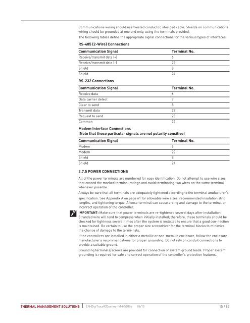
Communications wiring should use twisted conductor, shielded cable. Shields on communicationswiring should be grounded at one end only, using the terminals provided.The following tables define the appropriate signal connections for the various types of interfaces:RS-485 (2-Wire) ConnectionsCommunication SignalTerminal No.Receive/transmit data (+) 6Receive/transmit data (-) 22Shield 8Shield 24RS-232 ConnectionsCommunication SignalTerminal No.Receive data 6Data carrier detect 7Clear to send 8Transmit data 22Request to send 23Common 24Modem Interface Connections(Note that these particular signals are not polarity sensitive)Communication SignalTerminal No.Modem 6Modem 22Shield 8Shield 242.7.5 POWER CONNECTIONSAll of the power terminals are numbered for easy identification. Do not attempt to use wire sizesthat exceed the marked terminal ratings and avoid terminating two wires on the same terminalwhenever possible.Always be sure that all terminals are adequately tightened according to the terminal anufacturer’sspecification. See Appendix A on page 61 for allowable wire sizes, recommended insulation striplengths, and tightening torque. A loose terminal can cause arcing and damage to the terminal orincorrect operation of the controller.IMPORTANT: Make sure that power terminals are re-tightened several days after installation.Stranded wire will tend to compress when initially installed; therefore, these terminals should bechecked for tightness several times after the system is installed to ensure that a good con-nectionis maintained. Be certain to use the proper size screwdriver for the terminal blocks to minimizethe chance of damage to the termi-nals.If the controllers are installed in either a metallic or non-metallic enclosure, follow the enclosuremanufacturer’s recommendations for proper grounding. Do not rely on conduit connections toprovide a suitable ground.Grounding terminals/screws are provided for connection of system ground leads. Proper systemgrounding is required for safe and correct operation of the controller’s protection features.THERMAL MANAGEMENT SOLUTIONS EN-<strong>Digi<strong>Trace</strong></strong><strong>920</strong>series-IM-H56874 04/1315 / 82