DigiTrace 920 Series Heat Trace Controller - Pentair Thermal ...
DigiTrace 920 Series Heat Trace Controller - Pentair Thermal ...
DigiTrace 920 Series Heat Trace Controller - Pentair Thermal ...
You also want an ePaper? Increase the reach of your titles
YUMPU automatically turns print PDFs into web optimized ePapers that Google loves.
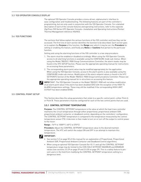
3.3 <strong>920</strong> Operator Console Display3.4 <strong>920</strong> Functions3.5 Control Point SetupThe optional <strong>920</strong> Operator Console provides a menu-driven, alphanumeric interface toease configuration and troubleshooting. The following features are part of the controller’sprogramming, but are only used in conjunction with the <strong>920</strong> Operator Console. For a detaileddescription of each of the console features and operating instructions, refer to the separate<strong>Digi<strong>Trace</strong></strong> <strong>920</strong> <strong>Series</strong> HTC Operator Console—Installation and Operating Instructions (<strong>Pentair</strong><strong>Thermal</strong> Managament reference H56903).The sections that follow explain the various functions of the <strong>920</strong> controller and how they can beaccessed. The first line of each section identifies the function to be described. Each section goeson to explain the Purpose of the function, the Range over which it may be set, the Procedure forsetting or enabling the feature, and finally any Notes or Cautions that pertain to the particularfunction.Setting and using the alarming functions of the <strong>920</strong> controller is a two step procedure:1. The alarm must be enabled or disabled accordingly. When using the <strong>920</strong> Operator Console,access to all alarming functions is available using the CONFIGURE mode sub-menus. Whenusing the Model 780/GCC-9000 Group Communications <strong>Controller</strong>, the alarm masks may befound in the HTC SETUP Section. Please see the appropriate operating manual for instructionson accessing these parameters.2. The corresponding alarm point value may be modified appropriately for the application.When using the <strong>920</strong> Operator Console, access to the alarm points is also available using theCONFIGURE mode sub-menus. Modification of the alarm setpoint values is found in the HTCSETPOINTS Section of the Model 780/GCC-9000 Group Communications <strong>Controller</strong>. Please seethe appropriate operating manual for in-structions on accessing this feature.IMPORTANT: The <strong>920</strong> Operator Console or the Model 780/GCC-9000 will not allow modificationof an alarm point value if the alarm has been disabled (DIS) with the exception of the HIGH TSALARM temperature settings. These may still be modified if the corresponding HIGH LIMITCUTOUT has been enabled (ENA).This Section describes the setup parameters that relate to a specific control point—either Point Aor Point B. These parameters must be configured for each of the two control points that are used.3.5.1 CONTROL SETPOINT TEMPERATUREPurpose: The CONTROL SETPOINT temperature is the value at which the heat trace controllermaintains the circuit temperature through either proportional, proportional ambient SSR,proportional ambient contactor, or deadband control, depending on the controllers’ configuration.The CONTROL SETPOINT temperature is compared to the temperature measured by the controltemperature sensor (TS). A decision is then made to turn on or turn off the output to control powerto the tracer.Range: –76°F to 1058°F (–60°C to 570°C)Procedure: Adjust the CONTROL SETPOINT temperature value to the desired maintaintemperature. The HTC will switch the output ON and OFF in an attempt to maintain thistemperature.IMPORTANT:• See section 5.2 on page 50 of this manual for an explanation of Proportional, ProportionalAmbient SSR, Proportional Ambient Contactor and Deadband Control algorithms.• When using an optional <strong>920</strong> Operator Console (for V3.11 and up) the CONTROL SETPOINTtemperature range may be limited to the CON-SOLE SETPOINT MAXIMUM and MINIMUMvalues (see sections 3.5.29 on page 29 and 3.5.30 on page 29). This is a safety feature to preventusers in the field from modifying the CONTROL SETPOINT temperature setting to adangerous level.THERMAL MANAGEMENT SOLUTIONS EN-<strong>Digi<strong>Trace</strong></strong><strong>920</strong>series-IM-H56874 04/1319 / 82


