DigiTrace 920 Series Heat Trace Controller - Pentair Thermal ...
DigiTrace 920 Series Heat Trace Controller - Pentair Thermal ...
DigiTrace 920 Series Heat Trace Controller - Pentair Thermal ...
You also want an ePaper? Increase the reach of your titles
YUMPU automatically turns print PDFs into web optimized ePapers that Google loves.
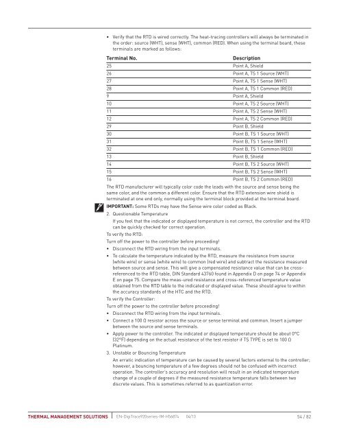
• Verify that the RTD is wired correctly. The heat-tracing controllers will always be terminated inthe order: source (WHT), sense (WHT), common (RED). When using the terminal board, theseterminals are marked as follows:Terminal No.description25 Point A, Shield26 Point A, TS 1 Source (WHT)27 Point A, TS 1 Sense (WHT)28 Point A, TS 1 Common (RED)9 Point A, Shield10 Point A, TS 2 Source (WHT)11 Point A, TS 2 Sense (WHT)12 Point A, TS 2 Common (RED)29 Point B, Shield30 Point B, TS 1 Source (WHT)31 Point B, TS 1 Sense (WHT)32 Point B, TS 1 Common (RED)13 Point B, Shield14 Point B, TS 2 Source (WHT)15 Point B, TS 2 Sense (WHT)16 Point B, TS 2 Common (RED)The RTD manufacturer will typically color code the leads with the source and sense being thesame color, and the common a different color. Ensure that the RTD extension wire shield isterminated at one end only, normally using the terminal block provided at the terminal board.IMPORTANT: Some RTDs may have the Sense wire color coded as Black.2. Questionable TemperatureIf you feel that the indicated or displayed temperature is not correct, the controller and the RTDcan be quickly checked for correct operation.To verify the RTD:Turn off the power to the controller before proceeding!• Disconnect the RTD wiring from the input terminals.• To calculate the temperature indicated by the RTD, measure the resistance from source(white wire) or sense (white wire) to common (red wire) and subtract the resistance measuredbetween source and sense. This will give a compensated resistance value that can be crossreferencedto the RTD table, DIN Standard 43760 found in Appendix D on page 74 or AppendixE on page 75. Compare the meas-ured resistance and cross-referenced temperature valueobtained from the RTD table to the indicated or displayed value. These should agree to withinthe accuracy standards of the HTC and the RTD.To verify the <strong>Controller</strong>:Turn off the power to the controller before proceeding!• Disconnect the RTD wiring from the input terminals.• Connect a 100 Ω resistor across the source or sense terminal and common. Insert a jumperbetween the source and sense terminals.• Apply power to the controller. The indicated or displayed temperature should be about 0°C(32°F) depending on the actual resistance of the test resistor if TS TYPE is set to 100 ΩPlatinum.3. Unstable or Bouncing TemperatureAn erratic indication of temperature can be caused by several factors external to the controller;however, a bouncing temperature of a few degrees should not be confused with incorrectoperation. The controller’s accuracy and resolution will result in an indicated temperaturechange of a couple of degrees if the measured resistance temperature falls between twodiscrete values. This is sometimes referred to as quantization error.THERMAL MANAGEMENT SOLUTIONS EN-<strong>Digi<strong>Trace</strong></strong><strong>920</strong>series-IM-H56874 04/13 54 / 82


