DigiTrace 920 Series Heat Trace Controller - Pentair Thermal ...
DigiTrace 920 Series Heat Trace Controller - Pentair Thermal ...
DigiTrace 920 Series Heat Trace Controller - Pentair Thermal ...

Create successful ePaper yourself
Turn your PDF publications into a flip-book with our unique Google optimized e-Paper software.
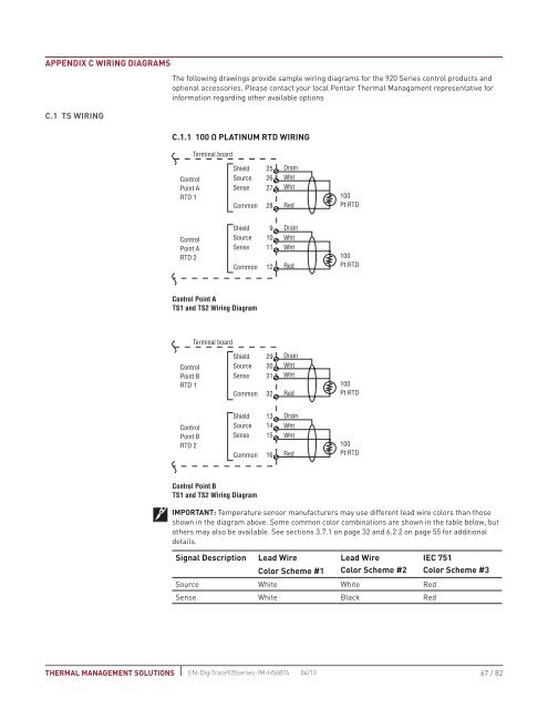
Appendix C Wiring DiagramsC.1 TS WiringThe following drawings provide sample wiring diagrams for the <strong>920</strong> <strong>Series</strong> control products andoptional accessories. Please contact your local <strong>Pentair</strong> <strong>Thermal</strong> Managament representative forinformation regarding other available optionsC.1.1 100 Ω PLATINUM RTD WIRINGTerminal boardShield 25 DrainControlPoint ASourceSense2627WhtWhtRTD 1 100Common 28 RedPt RTDControlPoint ARTD 2ShieldSourceSenseCommon9101112DrainWhtWhtRed100Pt RTDControl Point ATS1 and TS2 Wiring DiagramTerminal boardShield 29 DrainControl Source 30 WhtPoint BSense 31 WhtRTD 1 100Common 32 RedPt RTDControlPoint BRTD 2ShieldSourceSenseCommon13141516DrainWhtWhtRed100Pt RTDControl Point BTS1 and TS2 Wiring DiagramIMPORTANT: Temperature sensor manufacturers may use different lead wire colors than thoseshown in the diagram above. Some common color combinations are shown in the table below, butothers may also be available. See sections 3.7.1 on page 32 and 6.2.2 on page 55 for additionaldetails.Signal Description Lead WireColor Scheme #1Lead WireColor Scheme #2IEC 751Color Scheme #3Source White White RedSense White Black RedTHERMAL MANAGEMENT SOLUTIONS EN-<strong>Digi<strong>Trace</strong></strong><strong>920</strong>series-IM-H56874 04/1367 / 82