STAINLESS STEEL IN FIRE (SSIF) - Steel-stainless.org
STAINLESS STEEL IN FIRE (SSIF) - Steel-stainless.org
STAINLESS STEEL IN FIRE (SSIF) - Steel-stainless.org

Create successful ePaper yourself
Turn your PDF publications into a flip-book with our unique Google optimized e-Paper software.
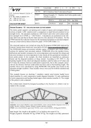
tis the time (s)β = 12.25α = λ a/ρ aC a(λ a=45 W/mK, C a= 600 J/KgK, ρ a= 7850 Kg/m 3 )θ lw= is the mean temperatures at the bottom edge of the web = κ 3 θ pin which θ pis thetemperature of the <strong>stainless</strong> steel plate and κ 3 is a reduction factor given in Table 4.6.Table 4.5Values of parameter θ o , a and bPart i of thebeamStainless steelplateLower flangeLower part of thewebUpper part of thewebArea A i Temperature θ I 1) Characteristic strengthf y,θiFull areaA p =e p ×b pFull areaA lf =e f ×b fUniform temperature distributionFor IF-beam: θ p = θ o - κ 1 ×e pFor SF-beam: θ p = θ o - κ 1 ×(e p +e f )Uniform temperature distributionθ lf = κ 2 ×θ pk 2,θp× f sy,20 °k y,θlf× f ay,20°CA wl = e w × h lChanges linearly from θ lw to 20°C f ay,20°C × (1+ k y,θlw )/2A ul = e w × (h w -h l ) Lower than 400°C f ya,20°CFull areaUpper flangeLower than 400°CA uf =e f ×b f1) θ o , κ 1 and κ 2 are empirical coefficients depending on the fire rating onlyf ya,20°CTable 4.6 Values of parameter θ o , κ 1 , κ 2 and κ 3Fireratingθ o κ 1 κ 3IF beam SF-beam IF beam SF beamκ 2IF beam SF beam30 570 500 7 3 0.75 - -60 830 775 6 3 0.85 0.77 0.7690 920 930 3 3 0.90 0.83 0.81120 980 1025 2 3 0.95 0.87 0.84The results obtained with the proposed design method were compared to the results predicted bynumerical analysis. For the numerical predictions, the beam was firstly subjected to the EN 1363-1standard fire curve for 60, 90 and 120 minutes under the effects of neighbouring vertical loads. Then thetemperature distribution was kept constant and a vertical load P was applied, which increased graduallyuntil the beams failed. The failure point of the beam was taken when the maximum mechanical strainin the <strong>stainless</strong> steel plate exceeded 2%, corresponding to a maximum deflection of L/15 to L/10. Ingeneral good agreement was achieved with the proposed design method and the numerical modeldiffering by no more than 10%. For a load ratio smaller than 0.7, a fire rating of R60 (i.e. 60 minutes)is easily achievable. An integrated beam can achieve R90 and a slim floor beam can achieve R120when the load ratio is lower than 0.5 without any applied fire protection.37