Building Flex Body Models - Kxcad.net
Building Flex Body Models - Kxcad.net
Building Flex Body Models - Kxcad.net
Create successful ePaper yourself
Turn your PDF publications into a flip-book with our unique Google optimized e-Paper software.
12<br />
Adams/<strong>Flex</strong><br />
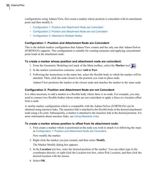
configurations using Adams/View, first create a marker whose position is coincident with its attachment<br />
point and then modify it.<br />
• Configuration 1: Position and Attachment Node are Coincident<br />
• Configuration 2: Position and Attachment Node are not Coincident<br />
• Configuration 3: Attached to Multiple Nodes<br />
Configuration 1: Position and Attachment Node are Coincident<br />
This is the default marker configuration that Adams/View creates and the only one that Adams/Solver<br />
(FORTRAN) supports. This configuration is suitable for creating measures and applying concentrated<br />
point loads at the attachment node.<br />
To create a marker whose position and attachment node are coincident:<br />
1. From the Geometric Modeling tool stack of the Main toolbox, select the Marker tool .<br />
2. In the marker construction container, select Add to Part.<br />
3. Following the instructions in the status bar, select the flexible body to which the marker will be<br />
attached. Then, click the node closest to the position you want to place node.<br />
Adams/View positions the marker at the closest node and attaches the marker to the same node.<br />
Configuration 2: Position and Attachment Node are not Coincident<br />
It is often necessary to add a marker to a flexible body where there is no node. For example, you may<br />
need to connect two flexible bodies whose nodes are not coincident or apply a force at a location offset<br />
from a node.<br />
A similar marker configuration which is compatible with the Adams/Solver (FORTRAN) can be<br />
obtained using massless links. The massless link is attached to the flexible body at the desired attachment<br />
node using a fix joint. Subsequently, a marker is attached to the massless link at the desired position. For<br />
more information about massless links, see Using Massless Links.<br />
To create a marker whose position is offset from its attachment node:<br />
1. First create a marker which is positioned at the node you wish to attach it to following the steps<br />
in Configuration 1: Position and Attachment Node are Coincident.<br />
Now modify the marker.<br />
2. Right-click the marker you just created, and then select Modify.<br />
The Marker Modify dialog box appears.<br />
3. In the Location text box, enter the desired position of the marker. You can either type in the<br />
coordinates directly; or right-click the Location text box, select Pick Location, and then click the<br />
desired location with the mouse.<br />
4. Select OK.


