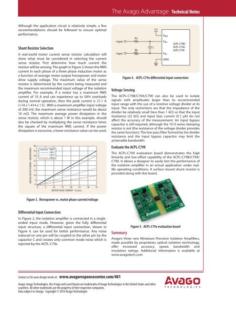
The Avago Advantage Technical NotesAlthough the application circuit is relatively simple, a fewrecommendations should be followed to ensure optimalperformance.Shunt Resistor SelectionA real-world motor current sense resistor calculation willshow what must be considered in selecting the currentsense resistor. First determine how much current theresistor will be sensing. The graph in Figure 3 shows the RMScurrent in each phase of a three phase induction motor asa function of average motor output horsepower and motordrive supply voltage. The maximum value of the senseresistor is determined by the current being measured andthe maximum recommended input voltage of the isolationamplifier. For example, if a motor has a maximum RMScurrent of 10 A and can experience up to 50% overloadsduring normal operation, then the peak current is 21.1 A(=10 x 1.414 x 1.5). With a maximum amplifier input voltageof 200 mV, the maximum sense resistance would be about10 mΩ. The maximum average power dissipation in thesense resistor, which is about 1 W in this example, shouldalso be checked by multiplying the sense resistance timesthe square of the maximum RMS current. If the powerdissipation is excessive, a lower resistance value can be used.MOTOR OUTPUT POWER - HORSEPOWER403530252015105005440 V380 V220 V120 V10 15 20 25 30MOTOR PHASE CURRENT - A (rms)35+Input–InputRaRbC5 VV DD1V IN+Figure 4. ACPL-C79x differential input connectionVoltage SensingThe ACPL-C79B/C79A/C790 can also be used to isolatesignals with amplitudes larger than its recommendedinput range with the use of a resistive voltage divider at itsinput. The only restrictions are that the impedance of thedivider be relatively small (less than 1 kΩ) so that the input affect the accuracy of the measurement. An input bypasscapacitor is still required, although the 10 Ω series dampingresistor is not (the resistance of the voltage divider providesthe same function). The low-pass filter formed by the dividerresistance and the input bypass capacitor may limit theachievable bandwidth.Evaluate the ACPL-C79XThe ACPL-C79X evaluation board demonstrates the highlinearity and low-offset capability of the ACPL-C79B/C79A/C790. It allows a designer to easily test the performance ofthe isolation amplifier in an actual application under reallifeoperating conditions. A surface mount shunt resistor isprovided along with the board.V IN–GND1ACPL-C79B/ACPL-C79A/ACPL-C790Figure 3. Horsepower vs. motor phase current/voltageDifferential Input ConnectionIn Figure 2, the isolation amplifier is connected in a singleendedinput mode. However, given the fully differentialinput structure, a differential input connection, shown inFigure 4, can be used for better performance. Any noiseinduced on one pin will be coupled to the other pin by thecapacitor C and creates only common mode noise which isrejected by the ACPL-C79x.SummaryFigure 5. ACPL-C79x evaluation boardAvago’s three new Miniature Precision Isolation Amplifiers,made possible by proprietary optical isolation technology,offer increased accuracy, speed, bandwidth andinsulation ratings. Additional information is available atwww.avagotech.comContact us for your design needs at: www.avagoresponsecenter.com/401Avago, Avago Technologies, the A logo and LaserStream are trademarks of Avago Technologies in the United States and othercountries. All other trademarks are the property of their respective companies.Data subject to change. Copyright © 2010 Avago Technologies
SIGNAL INTEGRITYBY HOWARD JOHNSON, PhDLinearityMy good friend Chris “Breathe” Frue is a talented musician, atrained audio engineer, and an excellent conversationalist.He asked recently, “What is the meaning of linearity, and whyshould I care?”I took a long puff on my pipe and answeredslowly, “Well, linearity is one oftwo properties essential for good signalfidelity—audio or otherwise. The otherproperty is time invariance. A linear,time-invariant system responds equallywell to loud and to soft inputs, whethercomposed of one sound or many.”“You are just waving your hands,”Breathe said. “I don’t buy it. There mustbe some more-concrete definition.”“There is,” I replied. “It’s tricky tostate the whole thing, so I’ll begin witha necessary condition, meaning thatevery linear systemmust atleast do this task.The conditionis called scaling.Scaling meansthat, if you turnup the volumeon the systeminput, the systemresponse scalesproportionately.Your guitar amplifier,for example,has the propertyof scaling.” (Breathe plays a fine oldarch-top jazz guitar. He uses a Mackiemixer driving a linear studio-qualitymonitor to produce a clean sound.He doesn’t need distortion because histechnique is impeccable.)“I don’t believe that,” Breathe said.“Look, if I tweak the volume knobon my guitar to 5, it sounds one way.If I turn it up to 10, the club managercomes over and tells me to turn itdown. So the response is totally differentin those two cases.”“Yes,” I answered. “And your speakerprobably distorts at the high setting,too, so that won’t be the same either,but what I’m saying is that, if you keepthe volume in a reasonable range, thenscaling works.”“Does the term ‘reasonable range’ includea setting of zero?” he asked.“Of course, zero is a perfectly validinput signal for any linear system,” Isaid. “The output would be zero.”“But it’s not,” said Breathe. “Evenwhen I set myguitar to zero, alittle hiss alwayscomes out of thespeakers. So theamp is not, accordingto yourdefinition, linearfor either largescaleor smallscaleinputs.”At this point,I realized that,through earliersuch conversations,I had already taught Breathe fartoo much about electrical engineering.His questions were becoming dangerous.My next columns will lay out forhim, in a methodical but simple way,the whole concept of linear-time-invariantbehavior so he can understandits importance, not only as a tool formodeling but as an ideal standard of behavioragainst which you can measurecircuit performance.ON ANO<strong>THE</strong>R TOPIC, a recent article(Reference 1) generated a lot ofreader responses. Here are some of themore oft-repeated ideas. First, the precisevalues for the 10% resistor scale(10, 12, 15, 18, 22, 27, 33, 39, 47, 56,68, and 82) nearly fit an exponentialscale. The steps are adjusted so thatthe tolerance bands in most cases overlap.For example, the nominal value of68Ω−10% gives 61.2, slightly smallerthan 56+10%, which equals 61.6.Only the gaps from 12 to 15Ω and 18to 22Ω violate this rule. Because mostI had taught himfar too much aboutelectrical engineering.His questionswere becomingdangerous.of the bands overlap, almost any resistoryou manufacture fits into some toleranceband somewhere on the scale.Few parts go to waste, and manufacturerslove this fact. The other tolerancescales—20, 5, and 2% and so on—havesimilar overlapping properties.Next, if you file the side of a carboncompositionresistor, notching throughits outer coating into the bulk carbonlayer, you can raise its resistance. Thisapproach makes every resistor a “variableresistor.” A drop of lacquer resealsthe outer coating. Don’t file too far!Finally, the value of a carbon-compositionresistor drifts with temperatureand with age. If you want longtermstability, you must prebake yourresistors.EDNREFERENCE1 Johnson, Howard, PhD, “7% solution,”EDN, June 10, 2010, pg 22, www.edn.com/article/509250-7_solution.php.Howard Johnson, PhD, of Signal Consulting,frequently conducts technical workshopsfor digital engineers at Oxford Universityand other sites worldwide. Visit hisWeb site at www.sigcon.com.SEPTEMBER 9, 2010 | EDN 21


![[270].pdf 37407KB Sep 02 2010 09:55:57 AM - ElectronicsAndBooks](https://img.yumpu.com/50350834/1/185x260/270pdf-37407kb-sep-02-2010-095557-am-electronicsandbooks.jpg?quality=85)
![draaien, A Viruly 1935 OCR c20130324 [320]. - ElectronicsAndBooks](https://img.yumpu.com/49957773/1/190x252/draaien-a-viruly-1935-ocr-c20130324-320-electronicsandbooks.jpg?quality=85)


![20051110 c20051031 [105].pdf 35001KB Feb 18 2009 08:46:32 PM](https://img.yumpu.com/48687202/1/190x253/20051110-c20051031-105pdf-35001kb-feb-18-2009-084632-pm.jpg?quality=85)


