designideasD 11N4148C 11 μFP X S NV CCP YFigure 2 This circuit can monitor 28additional pushbuttons if you usediodes to connect them to two ports.1-WIREGNDRSTZIOV CCIC 1DS2408GNDP0P1P2...P7Figure 1 This circuit connects to a microcontroller and can monitor eight pushbuttonsusing only two wires.a logic one indicates, for the 2 bits immediatelyafter the conditional-searchcommandcode. In that case, the microcontrollercancels the conditionalsearch and starts over.If IC 1responds to the conditionalsearch, the first 2 bits will be one andzero, representing the least-significantbit of the device’s family code, 29h,in its true and inverted forms. In thatcase, the microcontroller should completethe conditional-search flow, whichcomprises a 192-bit sequence. Next, themicrocontroller reads from IC 1by issuinga read-PIO-registers commandusing 008Ah, the address of the PIOactivity-latch-stateregister. The microcontrollerthen issues a 1-Wire reset, aR PD1MR PD1MR PD1MR PD1Mresume command, and a resume-and-reset-activity-latchescommand. It then returnsto the endless loop, polling for thenext pushbutton event.If IC 1responds and no other 1-Wireslave is connected, the microcontrollercould cancel the conditional search afterreading the first 2 bits, issue a 1-Wirereset, issue a skip-ROM command, andthen read the PIO-activity-latch-stateregister. Next, it must issue a 1-Wirereset, a skip-ROM command, and a reset-activity-latchescommand before returningto the endless loop.The code read from the PIO-activity-latch-stateregister tells which buttonwas pressed. If you press S 1, thedata is 00000001b; if you press S 2, it isS 1S 2S 3S 8...00000010b; and so forth. At least oneof the 8 bits will be one. If you press severalbuttons after the last reset-activitylatchescommand, several bits are one.The application software must then decidewhether such a condition is valid.In the simplest case, one-of-eight code,the software considers all codes thathave several bits at one as invalid.You can expand this concept to morethan eight pushbuttons. Instead of associatingone pushbutton with one port,you can associate additional pushbuttonswith two simultaneously activatedports, representing two-of-eight code(Figure 2). If another pushbutton activatesP Xor P Y, the diodes preventthat activity from propagating to otherports. Again, the application softwaremust check the code it reads from thePIO-activity-latch-state register to decidewhether it is valid. The theoreticallimit of this concept is 255 pushbuttons,which require combinations of two,three, four, five, six, seven, or eight diodesper additional pushbutton. Whenthe cost of diodes for each additionalpushbutton begins to exceed the benefits,you will find that adding anotherDS2408 is more cost-effective.EDNREFERENCE1 “DS2408 1-Wire 8-Channel AddressableSwitch,” Maxim Integrated ProductsInc, www.maxim-ic.com/ds2408.Tricolor LED emits lightof any color or hueMarián Štofka, Slovak University of Technology, Bratislava, Slovakia↘The human eye can see any coloras a mixture of blue, red, andgreen. The circuit in Figure 1 producesall three colors through an Avago(www.avagotech.com) ASMT-YTB0tricolor LED. You can produce a widerange of colors by varying the currentin the blue, red, and green LEDs.The collector outputs of bipolar differentialstages form the current sources. Aclassic symmetrical differential stage withtwo equal bipolar transistors is a backboneof almost all bipolar analog ICs. Inthis case, however, the differential stageis asymmetrical, with a 2-to-1 collectorcurrentdistribution instead of the common1-to-1 ratio at 0V base-voltage difference.The circuit produces the 2-to-1current ratio by paralleling a third equaltransistor, Q 3, to Q 1. The common collectorof the paralleled transistor pairconnects to the common emitter of theQ 4/Q 5differential stage. Thus, the basedifferential voltages equal 0V at both thestages, and collector currents I R, I G, andI Bare almost equal.52 EDN | SEPTEMBER 9, 2010
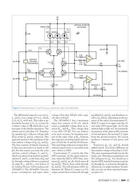
9VASMT-YTB0OPTICAL OUTPUT(R,G,B MIX)5.6kREDGREENI RI GIC 1BLUEI B82 nF2.5V+ ADR1581VOLTAGEREFERENCE−V REF1.25VIC 2Q 4≈I O –I BQ 3Q 5Q 6Q 1 Q 22.2kR BB2.2kV +IC 3B+V B100 nF15k0% REDP 215k0% GREEN82 nF+ADR1581−I O120 R BA2.2k2.2kIC 3A+V ADA4091-2100% BLUEV A15kP 115k0% BLUEFigure 1 Potentiometers P 1and P 2let you control the color of emitted light.The differential stages let you vary I R,I G, and I Bover a range of 0 to I O, whereI R+I G+I B≈I O=4.43 mA. This value is approximatebecause I R+I G+I Bis lower bya relative value of 3/β, where β is a currentgain of the bipolar transistors. Therelative error is less than 1%. TransistorQ 6equalizes Q 2’s collector voltage withthose of the Q 1and Q 3collectors. Thisapproach preserves the matching of thebase-emitter voltages of Q 1, Q 2, and Q 3.The base currents of bipolar transistorsin this case can reach to as much as 100μA. For this reason, you route the colorand hue control voltages, V Aand V B,which you derive from resistive potentiometersP 1and P 2, to the bases of Q 2andQ 5through voltage-follower-connectedop amps IC 3Aand IC 3B, two halves ofan Analog Devices’ (www.analog.com)ADA4091-2. The ADA4091-2 has lowpower consumption and input offsetvoltage of less than 500 μV with a typicalvalue of 80 μV.The ADA4091-2 has a maximuminput bias current of 65 nA, whichcauses a negligible voltage drop on resistorsR BAand R BB. This voltage dropis less than 130 μV. You can achieveeven more accuracy by inserting resistorsof the same value as R BAbetweenthe respective inverting inputs and outputsof both the A and the B followers.This step brings reduction of input-biascurrent-causederrors to one-sixth worstcase—down to 1/600.Potentiometer P 1controls the blueLED’s intensity. At the upper-end position,when the LED is 100% blue, transistorsQ 2and Q 3are off, which turns offQ 4and Q 5. Thus I Oflows solely throughQ 2and Q 6. The red and green LEDs aretherefore off. When P 1’s wiper is at 0V,output current flows exclusively throughparalleled Q 1and Q 3and distributes itselfto Q 4and Q 5, depending on the positionof the wiper of potentiometer P 2.With P 2’s wiper at its upper end, the circuitemits 100% green light. At 0V, theemitted light is fully red. An intermediateposition of the wiper yields a mixtureof red and green. By moving P 1’s wiperfrom the ground position, the circuitproduces a mixture of red, green, andblue.Transistors Q 1, Q 2, and Q 3shouldtightly match. You need a difference inbase-emitter voltages of less than 1.5 mV.The same requirement holds true for theQ 4/Q 5pair. Matching requirements areless stringent for Q 6. You should use abipolar NPN matched-transistor pair forQ 1through Q 6, or at least Q 1through Q 5,whereas Q 6is a single transistor. Eventually,you can use three matched-transistorpairs.EDNSEPTEMBER 9, 2010 | EDN 53


![[270].pdf 37407KB Sep 02 2010 09:55:57 AM - ElectronicsAndBooks](https://img.yumpu.com/50350834/1/185x260/270pdf-37407kb-sep-02-2010-095557-am-electronicsandbooks.jpg?quality=85)
![draaien, A Viruly 1935 OCR c20130324 [320]. - ElectronicsAndBooks](https://img.yumpu.com/49957773/1/190x252/draaien-a-viruly-1935-ocr-c20130324-320-electronicsandbooks.jpg?quality=85)


![20051110 c20051031 [105].pdf 35001KB Feb 18 2009 08:46:32 PM](https://img.yumpu.com/48687202/1/190x253/20051110-c20051031-105pdf-35001kb-feb-18-2009-084632-pm.jpg?quality=85)


