PIC18F to PIC24F Migration: An Overview - Microchip
PIC18F to PIC24F Migration: An Overview - Microchip
PIC18F to PIC24F Migration: An Overview - Microchip

You also want an ePaper? Increase the reach of your titles
YUMPU automatically turns print PDFs into web optimized ePapers that Google loves.
<strong>PIC18F</strong> <strong>to</strong> <strong>PIC24F</strong> <strong>Migration</strong>: <strong>An</strong> <strong>Overview</strong>INTRODUCTIONThe <strong>PIC24F</strong> architecture specification was created asa powerful extension of <strong>Microchip</strong>’s existing RISCmicrocontroller portfolio. By giving users an evengreater range of options for computational power andrich peripheral sets, it allows users <strong>to</strong> grow their applications.At the same time, the architecture was tailored<strong>to</strong> keep as much of the existing PICmicro ® MCU featureset and nomenclature as possible, making it easy forapplications <strong>to</strong> make the jump.This migration document highlights the similarities anddifferences between the <strong>PIC18F</strong> and <strong>PIC24F</strong> devicefamilies, and shows the general principles for migrating<strong>PIC18F</strong> applications <strong>to</strong> <strong>PIC24F</strong> devices. Throughoutthis document, it is assumed that the application <strong>to</strong> beported is based on a member of one of the later <strong>PIC18F</strong>device families, such as the popular <strong>PIC18F</strong>8722family, with a complete feature set and the latestversion of nanoWatt Technology of all <strong>PIC18F</strong> devices.The target device is assumed <strong>to</strong> be in the<strong>PIC24F</strong>J128GA general purpose family, which is thefirst generation of <strong>PIC24F</strong> general purpose devices.However, the general guidelines represented here canbe applied <strong>to</strong> migrating any <strong>PIC18F</strong> device-basedapplication <strong>to</strong> a <strong>PIC24F</strong> platform.To present such a comprehensive overview, it wasdecided <strong>to</strong> divide the material in<strong>to</strong> two major sections,each with a slightly different approach. The first sectioncompares and contrasts the core architectural differencesbetween the families, highlighting the majordifferences. Because the changes can greatly changethe overall structure of an application, the focus is no<strong>to</strong>n how <strong>to</strong> do specific tasks, but what larger changesneed <strong>to</strong> be considered in migration. The specific modificationsrequired are left <strong>to</strong> the user’s professionaljudgment.The second section discusses the peripherals that<strong>PIC18F</strong> and <strong>PIC24F</strong> architectures have in common.Like the core, module features are compared. Here, itis possible <strong>to</strong> also compare the steps needed <strong>to</strong> makeeach module run and give task-specific information.Only those peripheral features that are available in botharchitectures are presented here.Users are encouraged <strong>to</strong> review the <strong>PIC24F</strong> devicedata sheets for information on the new modules, andhow they may be used in applications that arecandidates for migration.Note 1: This device has been designed <strong>to</strong>perform <strong>to</strong> the parameters of its datasheet. It has been tested <strong>to</strong> an electricalspecification designed <strong>to</strong> determine itsconformance with these parameters. Due<strong>to</strong> process differences in the manufactureof this device, this device may have differentperformance characteristics than itsearlier version. These differences maycause this device <strong>to</strong> perform differently inyour application than the earlier version ofthis device.2: The user should verify that the deviceoscilla<strong>to</strong>r starts and performs asexpected. Adjusting the loading capaci<strong>to</strong>rvalues and/or the oscilla<strong>to</strong>r mode may berequired.Contents<strong>PIC24F</strong> Core Architecture .......................................... 2CPU Core............................................................ 2Instruction Set ..................................................... 4Memory Map and Program Memory ................... 7Data Memory Space ......................................... 11Resets and Start-up Timing............................... 13Interrupt Controller ............................................ 17Oscilla<strong>to</strong>r ........................................................... 19Power-Saving Features .................................... 23Watchdog Timer (WDT) .................................... 25Device Integration Features.............................. 26<strong>PIC24F</strong> Peripheral Set ............................................. 27I/O Ports............................................................ 27Timers (Timer1, Timer2/3 and Timer4/5)........... 29Capture/Compare/PWM (CCP and ECCP)....... 31Serial Peripheral Interface (SPI) ....................... 34Inter-Intergrated Circuit (I2C)..................... 36Universal AsynchronousReceiver/Transmitter (UART)............................ 3810-Bit A/D Converter......................................... 41Compara<strong>to</strong>r and Compara<strong>to</strong>r VoltageReference Modules........................................... 43Summary.................................................................. 45References............................................................... 45Mapping <strong>PIC18F</strong> <strong>to</strong> <strong>PIC24F</strong> Instructions.................. 47© 2006 <strong>Microchip</strong> Technology Inc. DS39764A-page 1
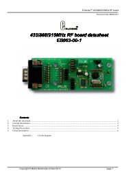
<strong>PIC24F</strong> CORE ARCHITECTURECPU CoreAside from its 16-bit data size, the <strong>PIC24F</strong> architectureis significantly different from the <strong>PIC18F</strong> architecture.The instruction word size, instruction clocking scheme,stack implementation and core registers are verydifferent from <strong>PIC18F</strong> implementations. Other hardwarefeatures have been added <strong>to</strong> enhance processingperformance. Changes are summarized in Table 1.TABLE 1:COMPARISON OF <strong>PIC18F</strong> AND <strong>PIC24F</strong> CPU CORE FEATURESFeature <strong>PIC18F</strong> <strong>PIC24F</strong>Instruction Size 16 bits 24 bitsInstruction Clocking TCY = FOSC/4 TCY = FOSC/2Working Registers 1 (W, WREG) 16 (W0-W15)Status Registers One (STATUS) Two (STATUS and CORCON)Stack Hardware, 31 levels SoftwareHardware Multiplier 8 x 8 17 x 17Hardware Divider No Hardware assisted division using DIV and REPEATBit Shifting/Rotation Single bit, left or right, rotation only Barrel shifting up <strong>to</strong> 15 bits, left or right, shift or rotateProgram Space Visibility(PSV)NoYesINSTRUCTION SIZEAll <strong>PIC18F</strong> devices use a 16-bit (single-word) instruction.<strong>PIC24F</strong> devices use a 24-bit instruction. A moredetailed discussion on instructions is presented in the“Instruction Set” section.INSTRUCTION CLOCKINGPICmicro microcontrollers execute instructions at a ratethat is a simple fraction of the clock speed, designatedas TCY. For the most part, <strong>PIC18F</strong> and <strong>PIC24F</strong> devicesperform most instructions with a fetch step and anexecution step of 1 TCY each. For <strong>PIC18F</strong> devices, eachTCY interval represents 4 clock cycles, with the PC beingincremented on falling edges. In contrast, the TCY for<strong>PIC24F</strong> devices is 2 clock cycles, with the PC beingincremented on leading clock edges. The differences ininstruction pipelining are shown in Figure 1. Thisdifference in instruction execution is one of the biggestdifferences between the two architectures, and needs <strong>to</strong>be taken in<strong>to</strong> consideration for any peripherals that usethe instruction clock speed as a base for their timing.FIGURE 1:COMPARISON OF <strong>PIC18F</strong> AND <strong>PIC24F</strong> INSTRUCTION EXECUTION PIPELINESDevice Clock<strong>PIC18F</strong> Program CounterPCPC + 2PC + 4<strong>PIC18F</strong> Execution PipelineExecute INST (PC – 2)Fetch INST (PC)Execute INST (PC)Fetch INST (PC + 2)Execute INST (PC + 2)Fetch INST (PC + 4)<strong>PIC24F</strong> Program Counter PC – 2PC PC + 2 PC + 4 PC + 6 PC + 8Fetch PC – 2 Execute PC – 2Fetch PC<strong>PIC24F</strong> Execution PipelineExecute PCFetch PC + 2 Execute PC + 2Fetch PC + 4 Execute PC + 4Fetch PC + 6 Execute PC + 6Fetch PC + 8DS39764A-page 2© 2006 <strong>Microchip</strong> Technology Inc.
W REGISTERSAll <strong>PIC18F</strong> devices have a single working register,known as W (sometimes, WREG). W is used as anoperand in almost all instructions, and is either thesource or destination for all instructions.The <strong>PIC24F</strong> architecture increases the number ofworking registers <strong>to</strong> 16, named W0 through W15. Mostinstructions allow for the selection of any one of theseas source and/or destination for the operation, althoughseveral instructions only allow the use of WREG (W0).Several of the registers have special functions. W0 andW1 are the working registers for the hardware-assisteddivider, and are required during divide (DIV) instructions.W2 and W3 are used by the MUL instruction asresult registers. W14 and W15 are used for a FramePointer and Stack Pointer, respectively.STATUS REGISTERS<strong>PIC18F</strong> devices have one ALU status register, namedSTATUS. It contains the normal flag bits for binarydigital math operations: Carry, Digit Carry, Zero state,Negative state and Overflow. All flags are writable aswell as readable.<strong>PIC24F</strong> devices use two status registers, which providethese ALU flags as well as CPU control bits. TheSTATUS register contains the standard ALU flagsalready listed; it also contains the RA flag <strong>to</strong> indicate anactive Repeat loop and the IPL2:IPL0 bits <strong>to</strong> set theCPU interrupt priority level.In addition <strong>to</strong> STATUS, <strong>PIC24F</strong> devices also have theCORCON register. It contains the IPL3 bit, whicheffectively enables or disables peripheral interrupts andthe PSV bit, which enables the Program SpaceVisibility feature (see “Data Memory Space” onpage 11 for more information).STACK<strong>PIC18F</strong> devices implement the program counter stackin hardware. The stack has a <strong>to</strong>tal of 32 levels, with onlythe <strong>to</strong>p layer being accessible <strong>to</strong> software. Stackpushes and pops are executed as instructions. <strong>An</strong>optional, non-maskable hardware trap (Reset) can beenabled for stack overflow and underflow events.In contrast, <strong>PIC24F</strong> devices implement a softwarestack in data RAM. The stack starts at RAM address0800h and grows <strong>to</strong>wards higher addresses. W15serves as the Stack Pointer and W14 is used as aFrame Pointer for higher level language applications.The upper limit of the stack is defined in software usingthe SPLIM register. Stack Pointer underflow andoverflow traps are generated when the Stack Pointer isdecremented below 0800h, or above the limit set bySPLIM.MULTIPLIERBoth <strong>PIC18F</strong> and <strong>PIC24F</strong> devices include a dedicatedhardware multiplier in their ALUs. The <strong>PIC18F</strong> multiplieris an 8 x 8 unit, capable of supporting signed,unsigned and mixed-sign operations. The <strong>PIC24F</strong>multiplier is a 17 x 17 unit and can also support signed,unsigned and mixed-signed operations. <strong>PIC18F</strong> multiplierscan perform 8-bit unsigned operations in a singleinstruction cycle, while <strong>PIC24F</strong> multipliers can performa 16-bit by 16-bit signed or mixed operation in a singlecycle.DIVIDER<strong>PIC18F</strong> devices do not provide any hardware supportfor division. Typical divide operations (signed 16/16 or16/8) performed, using the standard <strong>PIC18F</strong> mathlibrary, can take up <strong>to</strong> 38 instruction cycles <strong>to</strong> execute.<strong>PIC24F</strong> devices do not have a hardware divider per se.Instead, the <strong>PIC24F</strong> ALU is configured in hardware <strong>to</strong>support a divide instruction, DIV. Together with theREPEAT control instruction, DIV allows the ALU <strong>to</strong>au<strong>to</strong>matically execute the iterative division process asa simple sequence instead of a long algorithm. DIVsupports several forms of 32/16 and 16/16 divides,including fixed-point and fractional, and performsexecutions in 19 instruction cycles.BIT SHIFTS AND ROTATESThe <strong>PIC18F</strong> ALU is capable of performing single bitposition rotations, with or without carry, in either direction.<strong>An</strong>y byte operation that requires rotations of morethan one position will require an equal number ofinstruction cycles <strong>to</strong> perform the operation. Word lengthoperations are potentially longer and more complex, asbits need <strong>to</strong> be carried from one byte of data <strong>to</strong> another.The <strong>PIC24F</strong> ALU is equipped with a barrel shifter thatallows data <strong>to</strong> be either rotated or shifted (without wraparound),with or without carry, in either direction. Thispermits shifts of multiple bit positions in a single instructioncycle. Data can be rotated either as bytes for up <strong>to</strong>7 bits at a time, or as words for up <strong>to</strong> 15 bits at a time.© 2006 <strong>Microchip</strong> Technology Inc. DS39764A-page 3
Instruction SetThe <strong>PIC24F</strong> instruction set architecture represents aconsiderable extension of its <strong>PIC18F</strong> predecessor.While barely larger in terms of base instructions, itmakes substitutions of selected instructions <strong>to</strong>enhance the performance, while expanding the scopeof addressing modes and data type operations.Through all of this, the <strong>PIC24F</strong> instruction set maintainsthe highly orthogonal structure of previous PICmicroarchitectures.The main differences between the <strong>PIC18F</strong> and <strong>PIC24F</strong>instruction sets are presented in Table 2.TABLE 2:COMPARISON OF MAJOR INSTRUCTION SET FEATURESFeature <strong>PIC18F</strong> <strong>PIC24F</strong>Instruction Size 16 bits 24 bitsBase Instructions 75 76Supported Data Types Byte Byte, Word, Double WordOperand Support Up <strong>to</strong> binary (b = a + b) Up <strong>to</strong> trinary (a + b = c)Addressing Modes Direct, Indirect (5) Direct, Indirect (6)Indirect Addressing Type Uses FSR Pointer register sets; limit of3 pointersUses any of the W registers as pointers withinstruction-based manipulation; limit of 16Data Space AddressingShort literal, limited <strong>to</strong> a single bank a<strong>to</strong>ne time; full literal on few instructionsShort literal for entire Near Data Space;indirect address for entire spaceCHANGES FROM <strong>PIC18F</strong> INSTRUCTION SETThe <strong>PIC24F</strong> instruction set implements severalfeatures that enhance performance for math operations,and extend the ability <strong>to</strong> handle high-levellanguages with more complex stack and pointerrequirements. These are summarized in Table 3.In addition, several <strong>PIC18F</strong> instructions do not have anexact single instruction equivalent in the <strong>PIC24F</strong> architecture.Most of these instructions have either single orpairs of <strong>PIC24F</strong> instructions that have similar effect, butbecause of differences in the STATUS register, resultsare not exactly equivalent. They are:• CPFSEQ• INFSNZ• CPFSGT• MOVSF• CPFSLT• MOVSS• DCFSNZ• PUSHL• DECFSZ• SUBULNK• INCFSZ• TSTFSZ• MOVFF (all modes except indirect <strong>to</strong> indirect)• SWAPF (all modes except with WREG)Even with these changes, most <strong>PIC18F</strong> assemblerinstructions have a single-cycle equivalent in the<strong>PIC24F</strong> assembler. A comprehensive list is providedin Appendix A: “Mapping <strong>PIC18F</strong> <strong>to</strong> <strong>PIC24F</strong>Instructions”.TABLE 3:NEW OR SIGNIFICANTLY MODIFIED <strong>PIC24F</strong> INSTRUCTIONS<strong>PIC24F</strong> InstructionDescriptionDIV Divide two numbers (signed or unsigned, 16/16 or 32/16)LNK and UNLKLink or unlink Frame Pointer (W14)LSR and ASRLogical or arithmetic shift right by 1 <strong>to</strong> 16 bits, by either a literal or variable valueMUL.SS, MUL.SU, Specific instructions for multiplying signed and unsigned numbersMUL.USPUSH and POPBoth instructions now include source or destination arguments, allowing the stack <strong>to</strong>s<strong>to</strong>re values other then the current PCREPEATRepeat the next instruction a specified number of timesSLShift left by 1 <strong>to</strong> 16 bits by either a literal or variable valueDS39764A-page 4© 2006 <strong>Microchip</strong> Technology Inc.
SUPPORTED DATA TYPESAside from bit-oriented instructions, <strong>PIC18F</strong>instructions operate exclusively on single byte data.<strong>An</strong>y data that is longer than a single byte is handled byconcatenating bytes in the proper order.As 16-bit devices, <strong>PIC24F</strong> instructions are designed <strong>to</strong>handle data in terms of 16-bit words. In addition, mostinstructions are capable of handling single byte anddouble word (32-bit) data objects. Invoking this featureis generally done by using the suffix “.b” (for bytes) or“.d” (for double words) after the instruction mnemonic.Data alignment within the memory space is au<strong>to</strong>maticallyadjusted and maintained according <strong>to</strong> the datatype selected.OPERAND SUPPORTThe <strong>PIC18F</strong> instruction set supports both unary andbinary operations. That is <strong>to</strong> say, an instruction canfunction with a single argument operating on the contentsof one register (e.g., increment the WREG), orwith two arguments s<strong>to</strong>ring the results in one of the tworegisters (e.g., adding the contents of a register <strong>to</strong>WREG and s<strong>to</strong>ring the sum in WREG).The <strong>PIC24F</strong> instruction set also supports trinaryoperations; that is, an operation can have three arguments,specifying not only two operands but also anindependent address for the result. Trinary operationsare supported for most arithmetic and logic instructions.ADDRESSING MODESThe biggest difference between the <strong>PIC18F</strong> and<strong>PIC24F</strong> instruction sets is how the instructions specifyaddresses in the data memory space. While the methodsare equivalent, the <strong>PIC24F</strong> version allows moreoptions for more of its instructions.Direct AddressingWhile <strong>PIC18F</strong> instructions can directly address anyregister in the data space, very few specify a fulladdress as part of the instruction. Instead, most use an8-bit literal value <strong>to</strong> specify an address within one of16 banks of 256 bytes within the space. The bank inquestion is separately selected by the Bank SelectRegister (BSR).<strong>PIC24F</strong> instructions are designed <strong>to</strong> be able <strong>to</strong> literallyaddress any register within the lowest 8 Kbytes of thedata space (also known as the Near Data Space). Thisallows immediate access <strong>to</strong> all SFRs. Implementedmemory areas above the <strong>to</strong>p of the Near Data Spaceare accessible by indirect addressing, as describedbelow.Indirect Addressing<strong>PIC18F</strong> instructions perform indirect addressingthrough pointers and virtual registers. Three 12-bitpointers (FSR0 through FSR2) are loaded withappropriate values; then, one of five virtual registersassociated with that pointer is used as an argument foran instruction, either as an address or an offset for anaddress. Depending on which of the registers is used,the value of the pointer can also be au<strong>to</strong>matically incrementedor decremented. Only these three pointers andtheir associated registers can be used for indirectaddressing.In contrast, <strong>PIC24F</strong> architecture increases the numberof options for the addressing mode. <strong>An</strong>y one of the Wregisters can be used as a pointer for indirect addressing.Instead of using a virtual register name <strong>to</strong> determinethe pointer and its operation, the MPLAB ® IDEassembler language uses specific syntax conventions<strong>to</strong> indicate when a W register is being used as a pointeror offset, and what increment or decrement operation is<strong>to</strong> be done <strong>to</strong> the register. The <strong>PIC24F</strong> Instruction SetArchitecture (ISA) also offers a pre-decrement optionnot available with <strong>PIC18F</strong>. <strong>An</strong> additional feature of the<strong>PIC24F</strong> increment/decrement options is how they workwith the data type specified by the instruction. If theinstruction is executed as a byte type instruction, theregister will be incremented or decremented by one.This aligns the pointer <strong>to</strong> the next byte in memory whichis not always the next memory address. Word-orientedinstructions will increment or decrement the register bytwo and maintain proper word alignment.The differences between architectures in indirectaddressing modes and syntax are summarized inTable 4. A comparison of how <strong>to</strong> use these addressingmodes is shown in Example 1.TABLE 4:Indirect AddressingModeINDIRECT ADDRESSING IN <strong>PIC18F</strong> AND <strong>PIC24F</strong> INSTRUCTION SETS<strong>PIC18F</strong> VirtualRegister Operand<strong>PIC24F</strong> EquivalentSyntaxAfter ByteInstructionWn (or FSR)After WordInstructionNo Modification INDFx [Wn] Wn = Wn Wn = WnPre-Increment PREINCx [++Wn] Wn = Wn + 1 Wn = Wn + 2Pre-Decrement N/A [--Wn] Wn = Wn – 1 Wn = Wn – 2Post-Increment POSTINCx [Wn++] Wn = Wn + 1 Wn = Wn + 2Post-Decrement POSTDECx [Wn--] Wn = Wn – 1 Wn = Wn – 2Register Offset PLUSWx [Wn + Wb] Wn = Wn Wn = Wn© 2006 <strong>Microchip</strong> Technology Inc. DS39764A-page 5
EXAMPLE 1: COMPARISON OF INDIRECT ADDRESSING TECHNIQUESTypical <strong>PIC18F</strong> Code Sequence:LoopSetup MOVLW 0x10, LoopCount ;set up loop counterLFSR 0, myArray0 ;set up pointer 0LFSR 1, myArray1 ;set up pointer 1CopyLoop MOVFF POSTINC0, POSTINC1 ;copy myArray1 <strong>to</strong> myArray0DECFSZ LoopCount, F ;decrement loop counterBRA CopyLoop ;loopEquivalent <strong>PIC24F</strong> Code Sequence:LoopSetup MOV #myArray0, W0 ;set up pointer 0MOV #myArray1, W1 ;set up pointer 1CopyLoop REPEAT #15 ;loop 16 timesMOV [W1++], [W0++] ;copy array1 <strong>to</strong> arrayRAW DependenciesThe increased flexibility in addressing modes creates afew situations where Read-After-Write (or RAW)dependencies may be created. RAW dependenciesexist when a variable needed for an instruction that isbeing fetched stage has not been written back <strong>to</strong> theregister yet. These occur only in select situations,generally when a register used as a destination for oneinstruction is also an argument in an immediatelyfollowing instruction, and are listed in Table 5. The<strong>PIC24F</strong> CPU core includes “look ahead” detection forthese RAW hazards, and introduces one or more stall(NOP) cycles between instructions <strong>to</strong> avoid executionerrors.TABLE 5:SUMMARY OF READ-AFTER-WRITE DEPENDENCY RULESDestinationAddressing ModeUsing WnSourceAddressing ModeUsing WnRequired Stall(CPU cycles added<strong>to</strong> instruction time)Examples(Wn = W2)Direct Direct None ADD.w W0, W1, W2MOV.w W2, W3Indirect Direct None ADD.w W0, W1, [W2]MOV.w W2, W3Indirect Indirect None ADD.w W0, W1, [W2]MOV.w [W2], W3IndirectIndirect withpre/post-modificationIndirect withpre/post-modificationNoneADD.w W0, W1, [W2]MOV.w [W2++], W3Direct None ADD.w W0, W1, [W2++]MOV.w W2, W3Direct Indirect 1 ADD.w W0, W1, W2MOV.w [W2], W3DirectIndirect withpre/post-modification1 ADD.w W0, W1, W2MOV.w [W2++], W3Indirect Indirect 1 ADD.w W0, W1, [W2]MOV.w [W2], W3; W2=04h (mapped W2)IndirectIndirect withpre/post-modificationIndirect withpre/post-modificationIndirect withpre/post-modification1 ADD.w W0, W1, [W2]MOV.w [W2++], W3; W2=04h (mapped W2)Indirect 1 ADD.w W0, W1, [W2++]MOV.w [W2], W3Indirect withpre/post-modification1 ADD.w W0, W1, [W2++]MOV.w [W2++], W3DS39764A-page 6© 2006 <strong>Microchip</strong> Technology Inc.
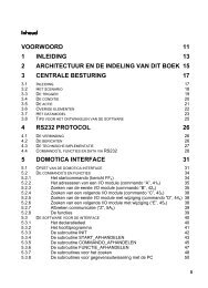
Memory Map and Program MemoryBoth <strong>PIC18F</strong> and <strong>PIC24F</strong> architectures use the samegeneral schema for their program memory spaces.Aside from the self-evident differences in width,<strong>PIC24F</strong> devices also incorporate a larger addressingrange and enhanced visibility features in data space.The organization of the space and the location ofnon-program memory features also differ somewhat,and must be considered when porting an application.The key differences between the memory organizationof <strong>PIC18F</strong> and <strong>PIC24F</strong> devices are presented inTable 6.TABLE 6:COMPARISON OF <strong>PIC18F</strong> AND <strong>PIC24F</strong> PROGRAM MEMORY ARCHITECTURESFeature <strong>PIC18F</strong> <strong>PIC24F</strong>Organization 16-bit, byte addressable 24-bit, word addressableTotal Addressable Range 4 Mbytes (22-bit magnitude) 16 Mbytes (24-bit magnitude)Maximum Available User Program Space 2 Mbytes (FFFFFh) 8 Mbytes (7FFFFFh)(upper boundary address)Boot Block Support Most devices NoInterrupt/Reset/Trap Vec<strong>to</strong>rs 00h, 08h, 18h 00h <strong>to</strong> 1FFhConfiguration Word Locations 300000h <strong>to</strong> 30000Fh Last 2 implemented locations inprogram memoryDevice ID Locations 3FFFFE and 3FFFFFh FF0000h and FF0002hORGANIZATIONThe <strong>PIC18F</strong> program space is organized as 16-bitwords, but is addressable in terms of bytes. Thismeans that the upper or lower byte of any word can beindividually addressed by a pointer. To maintain wordalignment for code execution, the memory space isaligned on the Least Significant Byte (LSB) of eachword, and the program counter increments by 2 duringnormal execution.The <strong>PIC24F</strong> program space has a different, but parallelstructure. It is physically organized as 24 bits wide, butis addressed as 16-bit words. Thus, an instruction isconsidered <strong>to</strong> be two words, not 3 bytes. Each wordcan be individually addressed with even addressesrepresenting the lower word of an instruction and oddaddresses the upper word. To maintain instructionalignment, the memory space is aligned on evenwords; the program counter increments by 2 duringnormal execution.Since a <strong>PIC24F</strong> instruction is three bytes wide, theMost Significant Byte of an instruction finds itself alonein the most significant word of the instruction as it iss<strong>to</strong>red in memory. To maintain word alignment whenreading from, or writing <strong>to</strong> program memory, a“phan<strong>to</strong>m byte” of 00h is added before the MSB <strong>to</strong> giveit the proper word length (Figure 2). The value reflectsthat this byte is not actually implemented in physicalprogram memory.Even with its word-aligned addressing, any single bytewithin the program space can be individually read orwritten. The <strong>PIC24F</strong> TBLRD and TBLWT commands areextended <strong>to</strong> allow an individual upper or lower byte ofany word <strong>to</strong> be accessed. Keep in mind that the upperbyte of any upper word (odd address) will always be00h, and cannot be written <strong>to</strong>, for reasons previouslydiscussed.FIGURE 2:<strong>PIC24F</strong> PROGRAM MEMORY ORGANIZATIONMSWAddressMost Significant WordLeast Significant WordPC Address(LSW Address)000001h000003h000005h000007h00000000000000000000000000000000231680000000h000002h000004h000006hProgram Memory‘Phan<strong>to</strong>m’ Byte(read as ‘0’)Instruction Width© 2006 <strong>Microchip</strong> Technology Inc. DS39764A-page 7
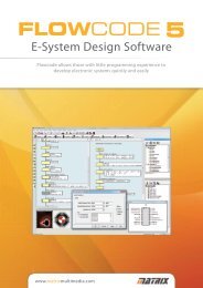
ADDRESSABLE AND USER-AVAILABLE RANGEBoth architectures base the size of their program spaceentirely on the size of the program counter. <strong>PIC18F</strong>devices use a 22-bit program counter for a <strong>to</strong>taladdressable space of 4 Mbytes. <strong>PIC24F</strong> devices use a24-bit counter for a <strong>to</strong>tal range of 16 Mbytes.In addition, both architectures reserve the upper half ofthe addressable program space as “configurationspace”; this is largely unimplemented addresses, withseveral implemented areas for device configuration,identification and programming. Thus, the <strong>to</strong>tal maximumavailable space for program memory is 2 Mbytesfor <strong>PIC18F</strong> devices, and 8 Mbytes for <strong>PIC24F</strong> devices.It is worth noting that no device in either family entirelyimplements the full available range of program memoryspace.The program spaces for the two architectures areshown in comparison in Figure 3.FIGURE 3: COMPARISON OF <strong>PIC18F</strong> AND <strong>PIC24F</strong> PROGRAM MEMORY SPACES (1)<strong>PIC18F</strong> Family (2)<strong>PIC24F</strong> Family000000h000008h000018hReset Vec<strong>to</strong>rLow/High Interrupt Vec<strong>to</strong>rsGOTO InstructionReset AddressInterrupt Vec<strong>to</strong>r TableReservedAlternate Vec<strong>to</strong>r Table000000h000002h000004h0000FEh000100h000104h0001FEh000200hUser FlashProgram Memory(up <strong>to</strong> 128 Kbytes)Program Memory AreaUser FlashProgram Memory(up <strong>to</strong> 128K words)(Top of PM)Device Config Words(Top of PM)-4(Top of PM)Unimplemented(Read ‘0’s)Unimplemented(Read ‘0’s)1FFFFEh200000h7FFFFEh800000hReserved2FFFFFh300000h30000Fh300010hDevice ConfigurationRegistersConfiguration SpaceReservedReserved3FFFFEh3FFFFFhDEVID (2)DEVID (2)FEFFFEhFF0000hFFFFFFhNote 1: Memory areas are not shown <strong>to</strong> scale. Scales differ for <strong>PIC18F</strong> and <strong>PIC24F</strong> maps.2: Only the elements of program space common <strong>to</strong> all <strong>PIC18F</strong> devices are shown. Later features, such as BootBlocks and Flash Configuration Words (<strong>PIC18F</strong>XXJ Flash devices only) have been omitted for clarity.DS39764A-page 8© 2006 <strong>Microchip</strong> Technology Inc.
INTERRUPT/RESET/TRAP VECTORSIn <strong>PIC18F</strong> devices, three addresses at the bot<strong>to</strong>m ofprogram memory are reserved for hardware vec<strong>to</strong>rs.Application code for these devices places destinationaddresses for hardware Resets, high-level InterruptService Routines (ISRs) and low-level ISRs in 00h, 08hand 18h, respectively.In <strong>PIC24F</strong> devices, the reserved range is much larger:from 00h <strong>to</strong> 1FFh. Location 00h is still reserved for thehardware Reset vec<strong>to</strong>r. Addresses 06h through FFhare reserved for the main interrupt vec<strong>to</strong>r table, whichcontains 118 separate hardware address vec<strong>to</strong>rs(including 8 non-maskable hardware traps). Addresses100h through 1FFh contain an alternate interrupt vec<strong>to</strong>rtable, also of 118 hardware address vec<strong>to</strong>rs, that isreserved for use in Emulation mode.CONFIGURATION WORDS AND DEVICE IDSBoth <strong>PIC18F</strong> and <strong>PIC24F</strong> devices locate their fac<strong>to</strong>rydevice IDs in the configuration space above the programmemory area. <strong>PIC18F</strong> Configuration registers are alsolocated in configuration space, whereas <strong>PIC24F</strong> Configurationregisters are located in program memory.<strong>PIC18F</strong> devices locate their Configuration Words at300000h through 30000Fh, and device IDs at 3FFFFEhand 3FFFFFh. <strong>PIC24F</strong> devices locate their ConfigurationWords at the last two addresses in implementedprogram memory, and device IDs at FF0000h andFF0002h.BOOT BLOCK SUPPORTMany <strong>PIC18F</strong> devices allow users <strong>to</strong> reserve andindependently code-protect a small area at the base ofthe user program space (depending on the device,between 1 and 4K words) for an independentbootloader program.As of this writing, a similar feature is not implementedin <strong>PIC24F</strong> devices. This absence does not rule out theuse of bootloader programs; it only means that a dedicatedand separately protectable block of programmemory is not available.EXTERNAL MEMORY MAPPINGThe <strong>PIC18F</strong> architecture supports the use of externalmemory devices as program memory. This feature,known as the External Memory Interface (EMI), isactually implemented as part of the CPU core’s addressbus management system. The EMI allows the programaddress bus <strong>to</strong> address and retrieve data from off-chipdevices as if they were part of the 2 Mbyte, on-chip programspace. Multiple operating modes are implemented,such as using off-chip memory exclusively as programmemory. Because of the I/O requirements, the EMI isonly available on <strong>PIC18F</strong> devices with 80 or more pins.As of this writing, <strong>PIC24F</strong> devices do not offer thisfeature. Program size is limited <strong>to</strong> that of on-chipmemory.FLASH MEMORY OPERATIONMany <strong>PIC18F</strong> and <strong>PIC24F</strong> devices use selfprogrammableFlash technologies <strong>to</strong> implementprogram memory. The general schema of memoryoperations and how they are performed are verysimilar, such as:• the ability <strong>to</strong> self-program some or all of the Flashmemory during run time• the ability <strong>to</strong> program or reprogram a devicealready embedded in the application through a5-wire serial interface (In-Circuit SerialProgramming or ICSP), or during deviceoperation (Enhanced In-Circuit SerialProgramming or EICSP)• the use of erase and write blocks of defined sizes,and erase-before-write programming algorithms• the self-timed write process after filling a writebuffer block, which stalls CPU execution for oneor more TCYOnly those differences that may impact the migration ofan application are noted here.Register and Bit Nomenclature<strong>PIC18F</strong> and <strong>PIC24F</strong> devices all use a single controlregister and a single unlock register <strong>to</strong> control Flashoperations. Some register and bit names, as shown inTable 7, change between the architectures.TABLE 7:FLASH CONTROL REGISTERSAND BITS IN <strong>PIC18F</strong> AND<strong>PIC24F</strong> ARCHITECTURESFlash Register or BitDescription<strong>PIC18F</strong> <strong>PIC24F</strong>Flash Control Register EECON1 NVMCONFlash Key Register EECON2 NVMKEYEEPROM Data Register EEPGD —PM/EEPROM Destination CFGS —Select bitFlash Operation EnablebitFREE ERASEThe key Flash control bits (WR, WREN and WRERR)have the same names and functions in botharchitectures.© 2006 <strong>Microchip</strong> Technology Inc. DS39764A-page 9
Flash AddressingIn <strong>PIC18F</strong> devices, the target address of Flash operationsis specified by a 22-bit Table Pointer register,TBLPTR, that is composed of 3 single byte SFRs(TBLPTRL, TBLPTRH and TBLPTRU). All table readand write instructions use this pointer <strong>to</strong> address theentire memory space; however, only table read operationsare allowed when the configuration space isaddressed (TBLPTR = 1).In <strong>PIC24F</strong> devices, the target address for Flashoperations is specified by two registers: the 8-bit TablePage register (TBLPAG) which specifies a 64 Kbytearea of the program memory space, and one of the Wregisters <strong>to</strong> specify an exact address within a designatedpage. The value of the two registers <strong>to</strong>getherforms the Effective Address or EA. As with <strong>PIC18F</strong>devices, only read operations are allowed when theconfiguration space is addressed (TBLPAG = 1).Data Size in Table OperationsTable operations in the <strong>PIC18F</strong> architecture are allbyte-oriented. All bytes in the memory space are individuallyaddressable, with the particular byte (high orlow) defined by an odd or even address argument.As already mentioned, table operations in the <strong>PIC24F</strong>architecture can be byte or word-oriented. In the latter,the specific byte (high or low) is defined by theinstruction mnemonic itself (TBLRDH/TBLRDL andTBLWTH/TBLWTL). The byte option can also be specified<strong>to</strong> specifically operate on either byte of any givenword. Keep in mind, of course, that operations on theupper byte of the upper word will either return 00h, orhave no effect, for reasons previously described.Reading Program Memory in Run Time<strong>PIC18F</strong> devices can retrieve data from the programspace using the table read command. Data is retrievedone byte at a time.<strong>PIC24F</strong> devices can also retrieve data with table reads,either one word or one byte at a time. In addition, theycan also use the PSV feature <strong>to</strong> map a 32 Kbyte blockof the program space in<strong>to</strong> the <strong>to</strong>p half of the data spaceon a read-only basis. This is further explained in the“Data Memory Space” section on page 11.DATA EEPROMMany <strong>PIC18F</strong> devices offer on-chip, nonvolatile datamemory for the s<strong>to</strong>rage of constant or slowly changingapplication data. These EEPROM areas are readableand writable, and are controlled by the same registersused <strong>to</strong> operate the Flash program memory.As of this writing, <strong>PIC24F</strong> devices do not incorporatedata EEPROMs in any devices. Users requiring a place<strong>to</strong> keep nonvolatile application data can use an unusedblock of program memory for this purpose. Data can beaccessed and modified using table read and writeoperations, and read using PSV mode.DS39764A-page 10© 2006 <strong>Microchip</strong> Technology Inc.
Data Memory SpaceThe <strong>PIC24F</strong> data memory space is substantiallydifferent than that found in <strong>PIC18F</strong> devices. The size,organization and method of access have all beenchanged. The key differences between the twoarchitectures are shown in Table 8.TABLE 8:COMPARISON OF MAJOR DATA MEMORY SPACE FEATURESFeature <strong>PIC18F</strong> <strong>PIC24F</strong>Addressing Range (size) 12 bits (4,096 byte maximum) 16 bits (65,536 byte maximum)SegmentationLinear range, banked addressing; linear Linear range, no segmentationaddressing for some instructionsSpecial Access Areas Access RAM (bot<strong>to</strong>m of lowest bank,Near Data Space (bot<strong>to</strong>m 8K)<strong>to</strong>p of highest bank)SFR Location Top half of highest bank Distributed throughout Near MemoryStackHardware, 32 levels deep, not mappedin memory spaceSoft stack starting at 0800h, user-configurableend of stackData Access Byte (direct or indirect) Double word, word or byte (all direct or indirect)Hardware PSV No Yes, in<strong>to</strong> <strong>to</strong>p half of data spaceADDRESS RANGE AND SEGMENTATIONAll <strong>PIC18F</strong> devices have a data memory space with a12-bit address range. In theory, the data space has alinear range and can be addressed directly by severalof the <strong>PIC18F</strong> instructions. For the most part, however,the data space functions as a segmented space. Sincemost <strong>PIC18F</strong> instructions can only contain the 8 lowerbits of a data address, the data space is effectivelydivided in<strong>to</strong> 16 banks of 256 bytes each. The exactmemory location is also determined by the Bank SelectRegister (BSR) which contains the upper 4 bits of theaddress. The entire range of the data space is4 Kbytes, of which some or all, may be implemented asdata RAM.In contrast, the <strong>PIC24F</strong> data space is implemented asa single linear range of addresses. Most instructionscan directly access any address within the first8 Kbytes of the range without the use of bank selection.The entire data space range is 64 Kbytes. Of this, onlythe first 32 Kbytes are implementable as data RAM; theupper 32 Kbytes are a virtual memory space that isused for PSV (see “Program Space Visibility (PSV)”on page 11).A comparison of the data space maps is shown inFigure 4.SFR LOCATIONSIn <strong>PIC18F</strong> architecture, all SFRs are located at the very<strong>to</strong>p of data memory, generally from addresses F60h <strong>to</strong>FFh, as a more or less contiguous block.In <strong>PIC24F</strong> architecture, SFRs reside in the lowest2 Kbytes of the memory space, from addresses 0000hthrough 07FFh.SPECIAL ACCESS AREASThe effective segmentation of the <strong>PIC18F</strong> data spacemakes it necessary for some way of accessing SFRsand critical application data quickly. This is done bycreating a virtual data space bank, known as theAccess RAM, which is composed of the lower half ofthe lowest bank and the upper half of the upper bank.This scheme makes certain that the SFR space isalways available, regardless of the contents of theBSR. Use of the Access RAM is included as an argumentin <strong>PIC18F</strong> assembly language and is hard-codedin the instruction’s opcode.In the <strong>PIC24F</strong> data space, the first 8 Kbytes of dataRAM between the addresses of 0000h and 1FFFh arereferred <strong>to</strong> as the Near Data Space. Addresses in thisspace, including all SFRs, are accessible directly fromall direct memory access instructions.PROGRAM SPACE VISIBILITY (PSV)Both <strong>PIC18F</strong> and <strong>PIC24F</strong> architectures allow for thedirect access of information s<strong>to</strong>red in the programmemory space as data. For <strong>PIC18F</strong>, data from programmemory is read in the data space by use of TBLRDcommands, with access being done on a word-by-wordbasis.For <strong>PIC24F</strong> devices, program memory is also madeavailable through hardware-enabled Program SpaceVisibility (PSV). When used, any 32 Kbyte segment ofthe program space may be mapped in<strong>to</strong> the upper32 Kbyte area of the data space on a read-only basis.PSV uses a hardware register, PSVPAG, <strong>to</strong> define whichpage of program memory will be mapped. The PSV iscontrolled in software by the PSV bit (CORCON).© 2006 <strong>Microchip</strong> Technology Inc. DS39764A-page 11
FIGURE 4:COMPARISON OF <strong>PIC18F</strong> AND <strong>PIC24F</strong> DATA SPACE MAPS<strong>PIC18F</strong> Devices<strong>PIC24F</strong> Devices00hBank 0FFh00hBank 1FFh00hBank 2FFh00hBank 3FFh00hBank 4FFh00hBank 5FFh00hBank 6FFh00hBank 7FFh00hBank 8FFh00hBank 9FFh00hBank 10FFh00hBank 11FFh00hBank 12FFh00hBank 13FFh00hBank 14FFh00hBank 15FFhAccess RAMGPRGPRGPRGPRGPRGPRGPRGPRGPRGPRGPRGPRGPRGPRGPRGPRSFR000h05Fh060h0FFh100h1FFh200h2FFh300h3FFh400h4FFh500h5FFh600h6FFh700h7FFh800h8FFh900h9FFhA00hAFFhB00hBFFhC00hCFFhD00hDFFhE00hEFFhF00hF5FhF60hFFFhAccess BankAccess RAM LowAccess RAM High(SFRs)00h5Fh60hFFhNearDataSpaceSFR AreaData RAM Area(implementation varieswith device)PSV Space0000h07FFh0800h1FFFh2000h7FFFh8000hFFFFhBank determined by Bank Select Register (BSR)Note:GPR = General Purpose RAM. Memory spaces are shown at different relative scales.PROGRAM STACKAs discussed in the “CPU Core” on page 2, <strong>PIC18F</strong>devices use a hardware stack for program flowmanagement. The stack is not memory mapped andhas a fixed size of 32 levels.<strong>PIC24F</strong> architecture uses a stack implemented entirelyin mapped data space. The stack begins at 0800h inNear Data Memory, just outside of the SFR area, andgrows <strong>to</strong>wards higher memory addresses, using theW15 register as a dedicated pointer. The size of thestack is entirely user-defined with the SFR register,SPLIM, which sets the address for stack overflow traps.DATA ACCESSAs discussed in the “Instruction Set” section onpage 4, <strong>PIC18F</strong> architecture can only work with data interms of bytes. In contrast, the <strong>PIC24F</strong> data space,organized in 2-byte words, allows many instructions <strong>to</strong>work with data as bytes, words or double words(32 bytes). The data type is determined by theargument used with the instruction.DS39764A-page 12© 2006 <strong>Microchip</strong> Technology Inc.
Resets and Start-up TimingThe <strong>PIC24F</strong> device Reset system can be thought of asa superset of the <strong>PIC18F</strong> version. The same legacyResets are supported in either identical or functionallyequivalent methods:• Power-on Reset (POR)• Brown-out Reset (BOR)• External Master Clear Reset (MCLR)• Software Reset (RESET instruction)• Watchdog Timer (WDT) Reset• Stack Error (Overflow or Underflow)<strong>PIC24F</strong> devices enhance the system with Resets foradditional error states, along with enhanced reporting.The Reset states for SFRs and start-up timing fromResets also differs slightly. The major differences aresummarized in Table 9.TABLE 9:COMPARISON BETWEEN <strong>PIC18F</strong> AND <strong>PIC24F</strong> RESETSFeature Description <strong>PIC18F</strong> <strong>PIC24F</strong>Legacy Reset TypesAdditional Reset TypesBOR ConfigurationPOR, BOR, MCLR, RESET Instruction, WDT, Stack ErrorConfiguration Word Mismatch(<strong>PIC18F</strong>XXJ Flash devices)Configurable, software controllable inmany devicesIllegal Opcode/Uninitialized W,Configuration Word Mismatch, Trap ConflictTied <strong>to</strong> on-chip regula<strong>to</strong>rStack Underflow/Overflow Reset Reset Unmaskable trapSFR Reset States (1) Dependent on type of Reset Uniform for all Reset typesStart-up Timer Configurable Tied <strong>to</strong> regula<strong>to</strong>r configurationNote 1: Excluding RCON and OSCCON registers.ENHANCED EVENT REPORTINGAll <strong>PIC18F</strong> devices use a <strong>to</strong>tal of 7 flag bits <strong>to</strong> report themost immediately past Reset event. This includes5 bits in the RCON register and 2 stack event flags inthe STKPTR register. <strong>PIC18F</strong> devices, with later implementationsof nanoWatt Technology, also include acontrol bit (SBOREN), the Reset state of which can beused as an indirect flag. In all <strong>PIC18F</strong> devices, RCONflag bits are inverted sense: they are set in the absenceof the event and cleared when the event has occurred.The overlap of some bits in the indication of a particularReset state requires that all bits be assessed <strong>to</strong>determine which Reset event has just occurred.In contrast, <strong>PIC24F</strong> devices use 12 flag bits; 11 arelocated in the RCON register and one (STKERR) in theINTCON1 register. Each bit is closely associated with aparticular event, so the change of state in one bit givesa clearer idea of the event that has just occurred. Inaddition, separate Sleep and Idle flag bits are now used<strong>to</strong> indicate if the device is in one of the Power-Savingmodes. These can be used <strong>to</strong> identify exits on interruptfrom Sleep or Idle modes. All flag bits are standardsense and become set when the corresponding even<strong>to</strong>ccurs.The differences in Reset flag bits between <strong>PIC18F</strong> and<strong>PIC24F</strong> are summarized in Table 10. The specific bitstates and their corresponding Reset states arecompared in Table 11 and Table 12.TABLE 10:COMPARISON OF RESETFLAGS IN <strong>PIC18F</strong> AND <strong>PIC24F</strong>ARCHITECTURESRCON Bit Function <strong>PIC18F</strong> <strong>PIC24F</strong>MCLR Reset — EXTRSoftware Reset RI SWRPOR POR PORBOR BOR BORWDT Reset TO WDTOTrap Conflict Reset — TRAPRIllegal Operation or— IOPUWRUninitialized W RegisterConfiguration Word— CMMismatchSleep Mode PD SLEEPIdle Mode PD IDLEStack Overflow STKFUL STKERR (1)Stack Underflow STKUNF STKERR (1)Note 1: Implemented as a hardware trap rather thana Reset. See the “Interrupt Controller”section on page 17 for more details.© 2006 <strong>Microchip</strong> Technology Inc. DS39764A-page 13
TABLE 11:<strong>PIC24F</strong> RESET STATUS BITS STATESConditionProgramCounterTRAPRIOPUWREXTRSWRWDTOSLEEPIDLECMBORPORSTKERRPower-on Reset 000000h 0 0 0 0 0 0 0 u 0 1 0RESET Instruction 000000h 0 0 0 1 0 0 0 u 0 0 0Brown-out Reset 000000h 0 0 0 0 0 0 0 u 1 0 0MCLR: in Run mode 000000h 0 0 1 0 0 0 0 u 0 0 0in Idle mode 000000h 0 0 1 0 0 0 1 u 0 0 0in Sleep mode 000000h 0 0 1 0 0 1 0 u 0 0 0WDT Time-out Reset: in Run mode 000000h 0 0 0 0 1 0 0 u 0 0 0in Idle mode PC + 2 0 0 0 0 1 0 1 u 0 0 0in Sleep mode PC + 2 0 0 0 0 1 1 0 u 0 0 0Stack Overflow Reset 000000h 0 0 0 0 0 0 0 u 0 0 1Stack Underflow Reset (1) 000000h 0 0 0 0 0 0 0 u 0 0 1Trap Conflict Reset (1) 000000h 1 0 0 0 0 0 0 u 0 0 0Illegal Opcode/Uninitialized WREG 000000h 0 1 0 0 0 0 0 u 0 0 0Configuration Word Mismatch Reset 000000h u u u u u u u 1 u u uInterrupt Exit: from Idle mode (2) 0 0 0 0 0 0 1 u 0 0 0from Sleep mode(2)0 0 0 0 0 1 0 u 0 0 0Idle mode (execute PWRSAV 1) PC + 2 0 0 0 0 0 0 1 u 0 0 0Sleep mode (execute PWRSAV 0) PC + 2 0 0 0 0 0 1 0 u 0 0 0Legend: u = unchangedNote 1: <strong>PIC24F</strong> stack events are trap events and not Resets; they are listed here for comparison purposes only. See the“Non-Maskable Traps” section on page 17 for more information.2: Program counter is loaded with PC + 2 if the interrupt’s priority is less than or equal <strong>to</strong> the CPU interrupt priority level, orthe interrupt’s hardware vec<strong>to</strong>r if the priority is greater than the CPU priority.TABLE 12:<strong>PIC18F</strong> COMPARABLE RESET STATUS BITS STATESRCONSTKPTRConditionProgramCounterSBOREN (1)RITOPDPORBORSTKFULSTKUNFPOR 0000h 1 1 1 1 0 0 0 0BOR 0000h u (2) 1 1 1 u 0 u uRESET Instruction 0000h u (2) 0 u u u u u uMCLR: in PRI_RUN mode 0000h u (2) u u u u u u uin SEC_RUN or RC_RUN modes 0000h u (2) u 1 u u u u uin Idle or Sleep modes 0000h u (2) u 1 0 u u u uWDT Time-out: in any Run mode 0000h u (2) u 0 u u u u uin Idle or Sleep modes PC + 2 u (2) u 0 0 u u u uStack Full Reset (STVREN = 1) 0000h u (2) u u u u u 1 uStack Underflow Reset or Error0000h u (2) u u u u u u 1(STVREN = 1 or 0)Interrupt Exit from Power-Managed modes PC + 2 (3) u (2) u u 0 u u u uLegend: u = unchangedNote 1: SBOREN is not implemented in <strong>PIC18F</strong>XXJ Flash devices, or in devices with earlier versions of nanoWatt Technology.2: Reset state is ‘1’ for Power-on Reset and unchanged for all other Resets when software Brown-out Reset is enabled(BOREN1:BOREN0 Configuration bits = 01 and SBOREN = 1); otherwise, the Reset state is ‘0’.3: When the wake-up is due <strong>to</strong> an interrupt and the GIEH or GIEL bit is set, the PC is loaded with the interrupt vec<strong>to</strong>r(008h or 0018h).DS39764A-page 14© 2006 <strong>Microchip</strong> Technology Inc.
ADDITIONAL <strong>PIC24F</strong> RESETSBeyond the legacy Reset events supported by botharchitectures, <strong>PIC24F</strong> supports three new hardwareResets:• IOPUWR: Attempted execution of anunrecognized or undetectable instruction opcode,or an attempt <strong>to</strong> use an uninitialized register as anAddress Pointer• CM: <strong>An</strong> event has caused a mismatch betweenthe Flash Configuration Words and their counterpartsin configuration space, or the device hasdetected a parity error in the Configuration Words• TRAPR: Two trap events have occurred, with thesecond taking place before the first has beenclearedThese events have no equivalent in the <strong>PIC18F</strong>architecture.STACK ERROR EVENTSIn <strong>PIC18F</strong> devices, a stack overflow or underflow eventcauses a full device Reset when the STVREN Configurationbit is programmed. Even if a stack interrupt isnot enabled, the PC is reset <strong>to</strong> zero if an event occurs.The STKFUL or STKUNF flag bit is set in either event<strong>to</strong> indicate which event has occurred.In <strong>PIC24F</strong> devices, a stack event is treated as a softtrap and causes code execution <strong>to</strong> jump <strong>to</strong> the interruptvec<strong>to</strong>r at address 000Ah. No differentiation is madebetween overflow and underflow events. <strong>PIC24F</strong> trapevents, in general, are discussed in more detail in the“Non-Maskable Traps” section on page 17.BOR CONFIGURATION<strong>PIC18F</strong> devices have always provided some level ofconfigurability for BOR. At a minimum, the BOR can beenabled or disabled, and the BOR threshold (VBOR) setduring device programming, by using the BOREN andBORV1:BORV0 Configuration bits. Later <strong>PIC18F</strong>devices with nanoWatt Technology allow the BOR <strong>to</strong> beselectively controlled in software.For <strong>PIC24F</strong> devices, the BOR function is incorporatedin<strong>to</strong> the on-chip voltage regula<strong>to</strong>r. The BOR is alwaysenabled when the regula<strong>to</strong>r is enabled, and active whileVDD is below VBOR (2.35V <strong>to</strong> 2.6V, typically). The abilityof <strong>PIC24F</strong> devices <strong>to</strong> operate at maximum frequencyacross the normal operating voltage range makes a configurableBOR unnecessary. This is in contrast <strong>to</strong> many<strong>PIC18F</strong> devices, where maximum frequency may betied <strong>to</strong> VDD, as described in the specific device datasheet. In these cases, it may be necessary <strong>to</strong> configurea BOR set point that reflects the application’s specificvoltage and frequency requirements.Note:<strong>PIC18F</strong>XXJ Flash devices, such as the<strong>PIC18F</strong>87J10, use BOR circuitry identical<strong>to</strong> <strong>PIC24F</strong> devices.SFR RESET STATESIn <strong>PIC18F</strong> devices, SFRs have up two designatedReset states: the default state on POR or BOR, and analternate state on all other legacy Resets. Dependingon the register’s function, the register values in the twostates are identical; but for many registers, the valueprior <strong>to</strong> the Reset is preserved.In <strong>PIC24F</strong> devices, there is no distinction betweenPOR/BOR and other Resets. All registers return <strong>to</strong> theiroriginal default values on a device Reset, regardless ofthe source. The only exceptions <strong>to</strong> this rule are theOSCCON and RCON registers, where the Reset valueof one or more bits is dependent on device configurationor state immediately prior <strong>to</strong> Reset.Data sheets and other literature for <strong>PIC18F</strong> devicesoften list a third Reset state: the value immediatelyfollowing a wake-up by WDT time-out or interrupt. Foralmost all registers in all <strong>PIC18F</strong> devices, the value isthe same as that immediately before the wake-upevent. For <strong>PIC24F</strong> devices, all SFRs are assumed <strong>to</strong>remain unchanged following a wake-up. Specificexceptions will be noted in the appropriate device datasheet.START-UP TIMING AFTER RESETS<strong>PIC18F</strong> devices include a fixed start-up timer that holdsthe microcontroller in a Reset state. The timer’sinterval, TPWRT, allows for the memory array <strong>to</strong>power-up and internal circuits <strong>to</strong> reach their initialstates. The power-up timer can be enabled or disabledduring device configuration by programming the PWRTConfiguration bit. Additional delays are added <strong>to</strong>TPWRT depending on the start-up oscilla<strong>to</strong>r selectedand whether or not the internal PLL is being used.For <strong>PIC24F</strong> devices, the start-up time is dependent onthe configuration of the on-chip voltage regula<strong>to</strong>r whenthe device exits a POR or BOR event. The <strong>to</strong>tal regula<strong>to</strong>rdelay is TSTARTUP, which is equal <strong>to</strong> TPWRT (if theregula<strong>to</strong>r is disabled) or TVREG (if it is enabled). TPWRTis a fixed, 64 ms nominal delay and is comparable <strong>to</strong>the <strong>PIC18F</strong> TPWRT delay; it provides time for the powersupply <strong>to</strong> stabilize. TVREG is a nominal, 10 μs delaywhich permits the internal voltage regula<strong>to</strong>r <strong>to</strong> stabilize.<strong>An</strong> additional voltage regula<strong>to</strong>r delay occurs if VREGS(RCON) is clear. Additional delays are also providedfor oscilla<strong>to</strong>r start-up and PLL, if enabled, whichare consistent with <strong>PIC18F</strong> devices. See the devicedata sheets for more information.OTHER RESET FEATURESMany <strong>PIC18F</strong> devices with later implementations ofnanoWatt Technology have a configurable MCLR pin.For these devices, the MCLRE Configuration bit canselect if the pin functions as the device Master Clear, oras an input only I/O port. <strong>PIC24F</strong> devices have “fixed”MCLR pins that cannot be reconfigured.© 2006 <strong>Microchip</strong> Technology Inc. DS39764A-page 15
MIGRATION CONSIDERATIONSFor applications that require polling of Reset events,the method of polling will need <strong>to</strong> be changed. Althoughall states that were tracked in <strong>PIC18F</strong> devices are stilltrackable in <strong>PIC24F</strong>, the meaning of the legacy RCONflag bits is more narrowly defined. It is no longer necessary<strong>to</strong> read all flags <strong>to</strong> interpret the immediatelyprevious event; for most cases, it will only be necessary<strong>to</strong> see which flag bit is now set. Note that the <strong>PIC24F</strong>RCON status bits are active-high and <strong>PIC18F</strong> RCONbits are active-low.Be aware that the start-up time of the device increaseswhen the regula<strong>to</strong>r is disabled <strong>to</strong> permit the applicationvoltage <strong>to</strong> stabilize. Enabling the regula<strong>to</strong>r also enablesthe BOR function.Note:The internal regula<strong>to</strong>r should not be used<strong>to</strong> power circuitry outside of the device. It isintended for internal power consumptiononly.It is recommended for both architectures <strong>to</strong> connectMCLR <strong>to</strong> VDD using a 1 kΩ resis<strong>to</strong>r. This will limit thecurrent flow in<strong>to</strong> the MCLR pin due <strong>to</strong> potential externaloverstresses.DS39764A-page 16© 2006 <strong>Microchip</strong> Technology Inc.
Interrupt ControllerThe <strong>PIC24F</strong> interrupt controller contains manyimproved interrupt options compared <strong>to</strong> the <strong>PIC18F</strong>.These new features include, but are not limited <strong>to</strong>,increased processor exceptions, software traps anduser-selectable priority levels. Table 13 summarizesthe differences between the <strong>PIC18F</strong> and <strong>PIC24F</strong>interrupts.TABLE 13:COMPARISON BETWEEN <strong>PIC18F</strong> AND <strong>PIC24F</strong> INTERRUPT CONTROLLERSInterrupt Features <strong>PIC18F</strong> <strong>PIC24F</strong>Unique Interrupt Flag and Enable for each Source Yes YesGlobal Interrupt Enable Yes YesSoftware Clearable Interrupt Flags Yes YesFlags Set Regardless if Interrupt is Enabled or Disabled Yes YesSoftware can Generate any Peripheral Interrupt Yes YesAu<strong>to</strong>matic Context Save/Res<strong>to</strong>re Yes YesExits Power-Managed Modes Yes YesAssignable Interrupt Priority high or low 8 levels, user-definedLatency for External Interrupt Events (INTx pins or the3 or 4 TCY 5 TCY (Fixed)PORTB input change interrupt)Priority Exit from Sleep and Idle Modes No YesInterrupt Nesting Disable Option No YesSoftware Selectable Core Interrupt Priority Level No YesTrap Vec<strong>to</strong>rs No Yes (4)Unique Interrupt/Trap Source No YesAlternate Interrupt Vec<strong>to</strong>r Table for Emulation No YesNatural priority Unmaskable or Non-Maskable Interrupts No YesCapable of Disabling Interrupts for Specific Number of TCY No YesNEW <strong>PIC24F</strong> INTERRUPT FEATURES• Unique Interrupt and Trap Vec<strong>to</strong>rs: Eachindividual interrupt source is assigned in hardwarea natural priority, allowing interrupts <strong>to</strong> be sortedwith no additional user intervention, as well as aunique interrupt vec<strong>to</strong>r• User-Assignable Priority: Users can also giveeach interrupt one of eight levels of priority, whichcan be used <strong>to</strong> override the natural priority• Software Assigned Core Priority: Users canalso set a threshold priority level at which theCPU will respond <strong>to</strong> interrupts• Interrupt Nesting: The use of natural priority anduser-assigned priority allows multiple interruptevents <strong>to</strong> be nested; this feature can also beselectively disabled• Hard and Soft Traps: Up <strong>to</strong> 8 non-maskable hardtraps with high natural priority are provided <strong>to</strong> flagpotentially serious events, such as math (divideby 0), stack overflow/underflow, address or dataalignment and oscilla<strong>to</strong>r failure• Alternate Vec<strong>to</strong>r Table: Allows for a convenientswitch between support and applicationenvironments without reprogramming• Priority Exit From Power-Saving modes:Allows the application <strong>to</strong> either resume normalcode execution, or jump <strong>to</strong> an ISR, depending onthe interrupt priority levelNote: For further information on traps, refer <strong>to</strong>the specific device data sheet.UNSUPPORTED <strong>PIC18F</strong> FEATURESAll <strong>PIC18F</strong> interrupt controller features are supported inthe <strong>PIC24F</strong> interrupt controller.NON-MASKABLE TRAPSIn <strong>PIC24F</strong> architecture, there are four hardware trapevents with interrupts that can never be disabled:• Address Decode Error• Oscilla<strong>to</strong>r Failure• Stack Error• Math (Overflow) Error© 2006 <strong>Microchip</strong> Technology Inc. DS39764A-page 17
These errors always force an immediate jump <strong>to</strong>specific interrupt vec<strong>to</strong>rs. The two most serious errors(Address Decode and Oscilla<strong>to</strong>r Failure) are hardtraps; these must be cleared before the CPU executioncan continue. All traps have their own individual flag bit.In addition <strong>to</strong> these unmaskable events, the <strong>PIC24F</strong>architecture can be expanded at a future time <strong>to</strong>include up <strong>to</strong> four additional traps.<strong>PIC18F</strong> architecture does not have an equivalent <strong>to</strong> thehardware trap. <strong>PIC18F</strong> stack error events are treatedas Resets.BIT NAME CHANGES AND MAPPING<strong>PIC24F</strong> devices maintain the same general nomenclaturefor interrupt bit names as <strong>PIC18F</strong> devices, with twoimportant differences. Both families maintain interruptenable, flag and priority bits that are generically namedxxxIE, xxxIF and xxxIP (where ’xxx’ is the mnemonic forthe interrupt source).The first major difference is the presence of three interruptpriority bits for each source, instead of the oneused for <strong>PIC18F</strong> devices. These bits, genericallynamed xxxIP2 through xxxIP0, allow the interrupt <strong>to</strong> beassigned one of eight relative priority levels.The other difference is the number of interrupt sources.While many interrupts have the same (or very similar)name as <strong>PIC18F</strong> devices, others are new. Other interruptshave similar names but have a different meaningfrom their <strong>PIC18F</strong> counterparts. Users should refer <strong>to</strong>the appropriate <strong>PIC24F</strong> device data sheet for acomplete list of interrupts and their meanings.SETUP AND ENABLING INTERRUPTSTo set up and enable interrupts on <strong>PIC18F</strong> devices:Required Steps:1. Clear the interrupt flag status bit associated withthe peripheral in the associated PIRx orINTCONx register.2. Enable the interrupt source by setting the interruptenable control bit associated with the sourcein the appropriate PIEx or INTCONx register.Note: The interrupt flag still needs <strong>to</strong> be clearedprior <strong>to</strong> exiting an ISR.Optional Step:Select the user-assigned priority level for the interruptsource by writing <strong>to</strong> the control bits in the RCON register;select high priority or low priority using the priority bit inthe corresponding IPRx register. The interrupt priorityfeature is enabled by setting the IPEN bit (RCON).To set up and enable interrupts on <strong>PIC24F</strong> devices:Required Steps:1. Set the NSTDIS bit (INTCON1) if nestedinterrupts are not desired.2. Clear the interrupt flag status bit associated withthe peripheral in the associated IFSx register.3. Enable the interrupt source by setting the interruptenable control bit associated with thesource in the appropriate IECx register.Note:Optional Step:Select the user-assigned priority level for the interruptsource by writing the control bits in the appropriate IPCxregister. The priority level will depend on the specificapplication and type of interrupt source. If multiple prioritylevels are not desired, the IPCx register control bit forall enabled interrupt sources may be programmed <strong>to</strong> thesame non-zero value.Note:The Interrupt/trap flag still needs <strong>to</strong> becleared prior <strong>to</strong> exiting an ISR.Upon Reset, all interrupts are assigned adefault priority level of 4.DISABLING USER INTERRUPTSTo disable interrupts on <strong>PIC18F</strong> devices, it is onlynecessary <strong>to</strong> clear the GIE bit (GIEH or GIEL if prioritylevels are used).To disable user interrupts on <strong>PIC24F</strong> devices, thesesteps are required:1. Push the current STATUS register value on<strong>to</strong>the software stack using the PUSH instruction.2. Force the CPU <strong>to</strong> priority level 7 by inclusiveORing the value OEh with the low byte of theSTATUS register (SRL). To enable user interrupts,the POP instruction may be used <strong>to</strong> res<strong>to</strong>rethe previous STATUS register value.Note: The DISI instruction allows interrupts ofpriority levels 1-6 <strong>to</strong> be disabled for a fixedperiod of time.MIGRATION CONSIDERATIONS<strong>PIC18F</strong> architecture only has the ability <strong>to</strong> assign eitherhigh or low priority interrupts <strong>to</strong> individual sources.<strong>PIC24F</strong> architecture allows the assignment of multiplepriority levels for interrupts (priorities 0 through 7 areuser defined and priorities 8 through 15 are hardwaredefined). At the very least, interrupts in native <strong>PIC18F</strong>applications will need <strong>to</strong> be re-assessed, and theirpriority levels redefined in <strong>PIC24F</strong> terms.For both <strong>PIC18F</strong> and <strong>PIC24F</strong> devices, the RETFIEinstruction exits an Interrupt Service Routine (ISR), butthis instruction does behave slightly different dependingon the microcontroller. For <strong>PIC18F</strong>, this instructionwill set the GIE bit <strong>to</strong> re-enable global interrupts. Sincethe GIE bit does not exist for <strong>PIC24F</strong>, this instructionwill res<strong>to</strong>re the previous priority level.DS39764A-page 18© 2006 <strong>Microchip</strong> Technology Inc.
Oscilla<strong>to</strong>rThe <strong>PIC24F</strong> oscilla<strong>to</strong>r system supports many of thefeatures of <strong>PIC18F</strong> nanoWatt Technology, and addsseveral new features. Both architectures support threemajor clock sources: primary oscilla<strong>to</strong>rs, internal RCoscilla<strong>to</strong>rs and 4x PLL frequency multipliers. In addition,both also support features <strong>to</strong> enhance applicationrobustness, such as software-controlled clock switching,Fail-Safe Clock Moni<strong>to</strong>rs and Two-Speed Start-up.<strong>PIC24F</strong> devices increase the flexibility of initial clockconfiguration, software controlled clock switching andthe use of the PLL.Although there are many similarities between <strong>PIC24F</strong>and <strong>PIC18F</strong> architectures in the oscilla<strong>to</strong>r and clockgeneration, there are also important differences in theimplementation of these features. Because the oscilla<strong>to</strong>raffects most aspects of an application, it is important<strong>to</strong> understand the differences before migrating anapplication <strong>to</strong> a <strong>PIC24F</strong> device.The major differences between the <strong>PIC18F</strong> and<strong>PIC24F</strong> clock structures are detailed in Table 14.CHANGES FROM <strong>PIC18F</strong> ARCHITECTUREFeatures added from the <strong>PIC18F</strong> implementation ofnanoWatt Technology include:• Enhanced PLL Operation: <strong>PIC24F</strong> architectureallows the PLL <strong>to</strong> be used under software control inall modes where it is available, and makes the PLLavailable <strong>to</strong> all External Primary Oscilla<strong>to</strong>r modes.• Doze Mode: This permits differential clocking ofthe CPU and peripherals, and allows the CPU <strong>to</strong>run at lower speeds while maintaining timingsensitive peripherals (see the “Power-SavingFeatures” section on page 23 for more details).<strong>PIC18F</strong> features that are no longer supported in<strong>PIC24F</strong> architecture include:• LP and External RC Primary Oscilla<strong>to</strong>r modeshave been removed in favor of SOSC and FRCOscilla<strong>to</strong>r modes• XT mode is still implemented, but is limited <strong>to</strong> theupper end of the upper range of frequenciesavailable with <strong>PIC18F</strong> devices. For <strong>PIC24F</strong>devices, the XT frequency range is 3.5 MHz <strong>to</strong>10 MHz.TABLE 14:COMPARISON OF MAJOR OSCILLATOR FEATURESFeature Description <strong>PIC18F</strong> <strong>PIC24F</strong>Primary (External) Oscilla<strong>to</strong>r ModesHS, XT, EC, LP andexternal RC (1)HS, XT and EC(all devices)Secondary (Timer1) Oscilla<strong>to</strong>r Yes Yes (SOSC)8 MHz Internal RC Oscilla<strong>to</strong>r Most devices (INTOSC) (1) Yes (FRC)31 kHz Internal RC Oscilla<strong>to</strong>r Yes (INTRC) Yes (LPRC)4x PLL Options:XTPLL (MSPLL)ECPLLINTOSCPLL/FRCPLLNoSelect devices onlySelect devices onlyINTOSC/FRC Tuning 5-bit magnitude, ±12% range 6-bit magnitude, ±12% rangeSoftware Clock Switching Between clock sources only Between all available oscilla<strong>to</strong>r types;uses safety interlockDoze Mode No YesFail-Safe Clock Moni<strong>to</strong>r Yes YesTwo-Speed Start-up Yes YesNote 1: Applies <strong>to</strong> most <strong>PIC18F</strong>XXXX devices, such as <strong>PIC18F</strong>8722. Currently, <strong>PIC18F</strong>XXJ Flash devices, suchas the <strong>PIC18F</strong>87J10, only offer HS and EC Primary Oscilla<strong>to</strong>r modes and no INTOSC oscilla<strong>to</strong>r.YesYesYes© 2006 <strong>Microchip</strong> Technology Inc. DS39764A-page 19
BIT AND CONTROL FUNCTION MAPPINGThere is not a precise one-<strong>to</strong>-one correspondencebetween configuration and control functions of the<strong>PIC18F</strong> and <strong>PIC24F</strong> architectures. The most commondifferences are shown in Table 15. Details arediscussed later in this section.TABLE 15:COMPARISON OF OSCILLATOR BIT AND CONTROL FUNCTION MAPPINGOscilla<strong>to</strong>r Block Function <strong>PIC18F</strong> <strong>PIC24F</strong>Define Start-up Oscilla<strong>to</strong>rDefine Primary Oscilla<strong>to</strong>r TypeDefine I/O Port Functions in EC Oscilla<strong>to</strong>rModesFOSC3:FOSC0(CONFIG1H) (1)FNOSC2:FNOSC0(Configuration Word 2)POSCMD1:POSCMD0(Configuration Word 2)OSCIOFCN(Configuration Word 2)Enable Secondary Oscilla<strong>to</strong>r T1OSCEN (T1CON) SOSCEN (OSCCON)Select INTOSC/FRC Postscaler IRCF2:IRCF0 (OSCCON) RCDIV2:RCDIV0 (CLKDIV)Switch Run-Time Clock SourceSCS1:SCS0 (OSCCON)NOSC2:NOSC0, OSWEN(OSCCON), FCKSM0(Configuration Word 2)Active Clock Source Moni<strong>to</strong>ring OSTS, IOFS, T1RUN COSC2:COSC0Enable Two-Speed Start-up IESO (CONFIG1H) IESO (Configuration Word 2)Enable Fail-Safe Clock Moni<strong>to</strong>rFCKSM1:FCKSM0FCMEN (CONFIG1H)(Configuration Word 2)Note 1: <strong>PIC18F</strong>XXXX devices only; FOSC2:FOSC0 (CONFIG2H) on current <strong>PIC18F</strong>XXJ Flash devices.PRIMARY OSCILLATORS (POSC)<strong>PIC18F</strong> microcontrollers, with the latest versions ofnanoWatt Technology, use an oscilla<strong>to</strong>r circuit that supportsa wide range of external components, including avariety of crystals, RC networks or external clock genera<strong>to</strong>rs.To use the oscilla<strong>to</strong>r, users connect their crystal orRC circuit <strong>to</strong> the OSC1 and OSC2 pins, or present theexternal clock on OSC1. The exact oscilla<strong>to</strong>r mode <strong>to</strong> beused is selected during device configuration using theFOSC3:FOSC0 Configuration bits, and must match theactual external circuit <strong>to</strong> be used.<strong>PIC24F</strong> microcontrollers support a similar range ofoscilla<strong>to</strong>r options on the OSC1 and OSC2 pins;however, the options for support of low-power,low-frequency crystals and external RC resonantcircuits have been omitted. These have been replacedby the use of a high-speed internal RC oscilla<strong>to</strong>r, andthe use of the Timer1 oscilla<strong>to</strong>r in the more flexibleclock structure.The primary oscilla<strong>to</strong>r mode is selected during configurationwith a combination of the FNOSC2:FNOSC0 andPOSCMD Configuration bits. Like <strong>PIC18F</strong>devices, the configuration must match the externalcircuit <strong>to</strong> be used in the application.SECONDARY OSCILLATOR (SOSC)All <strong>PIC18F</strong> devices have the option <strong>to</strong> use the Timer1oscilla<strong>to</strong>r as a secondary clock source. The mosttypical arrangement for this option is <strong>to</strong> connect alow-power, 32 kHz watch crystal across pins T1OSIand T1OSO. The oscilla<strong>to</strong>r is controlled separatelyfrom the device clock controls with the T1OSCEN bit(T1CON).<strong>PIC24F</strong> devices also provide a secondary oscilla<strong>to</strong>rthat is identical in function <strong>to</strong> the Timer1 oscilla<strong>to</strong>r; i<strong>to</strong>nly differs in that it is controlled through the OSCCONregister with the SOSCEN bit. The crystal input/outputpins are renamed SOSCI and SOSCO.The <strong>PIC24F</strong> secondary oscilla<strong>to</strong>r takes the place of thePrimary LP Oscilla<strong>to</strong>r mode provided on <strong>PIC18F</strong>devices, but not supported on <strong>PIC24F</strong>. To use SOSC asthe default oscilla<strong>to</strong>r on start-up, it must by selected indevice configuration by the FNOSC2:FNOSC0 bits andenabled in software by setting the SOSCEN bit.DS39764A-page 20© 2006 <strong>Microchip</strong> Technology Inc.
INTERNAL RC OSCILLATORS (INTOSC/FRCAND INTRC/LPRC)The internal oscilla<strong>to</strong>rs for <strong>PIC18F</strong> devices withnanoWatt Technology and <strong>PIC24F</strong> devices are virtuallyidentical, except in name. Both feature two independentinternal oscilla<strong>to</strong>rs, an efficient 31 kHz oscilla<strong>to</strong>r and anaccurate, high-speed 8 MHz oscilla<strong>to</strong>r. Both architecturesuse a configurable postscaler, driven by the 8 MHzsource, <strong>to</strong> provide a range of clock frequencies, from31 kHz <strong>to</strong> 4 MHz (as well as the undivided 8 MHzoutput). Both architectures allow software selection fromthe 31 kHz or 8 MHz oscilla<strong>to</strong>rs <strong>to</strong> provide the 31 kHzsource for various system features. Both clock systemspermit tuning of the 8 MHz source through a nominalrange of ±12%.The differences here are minor. For <strong>PIC18F</strong> devices,the internal 31 kHz and 8 MHz sources are generallyreferred <strong>to</strong> as INTOSC and INTRC. For <strong>PIC24F</strong>devices, they are known as the Fast RC (FRC) andLow-Power RC (LPRC) oscilla<strong>to</strong>rs. INTOSC/FRC tuningis accomplished with 5 tuning bits (TUN4:TUN0) in<strong>PIC18F</strong> devices; <strong>PIC24F</strong> devices use 6 tuning bits(TUN5:TUN0) for finer resolution. Finally, the defaultvalue on Reset for the 8 MHz postscaler is 1 MHz for<strong>PIC18F</strong> devices and 4 MHz for <strong>PIC24F</strong> devices.PLL FREQUENCY MULTIPLIER<strong>PIC18F</strong> and <strong>PIC24F</strong> devices both support a 4x PLLfrequency multiplier for use with select clock sources.In all cases, the PLL provides a stable output only whenthe input frequency is between 4 and 10 MHz. Theoperation of the PLL differs substantially between thetwo architectures.For most <strong>PIC18F</strong> devices incorporating nanoWattTechnology, the PLL is au<strong>to</strong>matically enabled forspecific, primary oscilla<strong>to</strong>r configurations and is alwaysoperational. All devices can use the HS oscilla<strong>to</strong>r withthe PLL; select later devices also allow the use of thePLL with the EC mode. These are distinct primaryoscilla<strong>to</strong>r configurations. If the user wishes <strong>to</strong> disable thePLL, the device must be reprogrammed and reconfigured.If the internal oscilla<strong>to</strong>r block is selected as thedevice’s default oscilla<strong>to</strong>r, the PLL is made availablewhen the INTOSC postscaler is configured for an outpu<strong>to</strong>f 4 or 8 MHz. In these cases, the PLL can be selectivelyenabled under software control with the PLLEN controlbit (OSCTUN).For <strong>PIC24F</strong> devices, the PLL is always available undersoftware control. It is available for all primary oscilla<strong>to</strong>rmodes, as well as FRC or FRCDIV operation (as longas a postscaler output of at least 4 MHz is selected). Touse the PLL, it is only necessary <strong>to</strong> perform a clockswitch <strong>to</strong> one of the PLL Clock modes. Once a PLLmode is selected, the state of the PLL’s output stabilityis indicated by the flag bit, LOCK (OSCCON).When the bit is set, the PLL output is stable.CLOCK SWITCHINGClock switching differs significantly between <strong>PIC18F</strong>and <strong>PIC24F</strong> devices. Conceptually, both architectureshave three categories of oscilla<strong>to</strong>rs: primary (externalcomponents connected <strong>to</strong> OSC pins), secondary(external crystal connected <strong>to</strong> T1OSC or SOSC pins)and internal RC. <strong>PIC18F</strong> devices permit the definitionof one and only one primary oscilla<strong>to</strong>r type used duringdevice configuration. This is the oscilla<strong>to</strong>r that is alwaysused when on device power-up and Reset. Thereafter,the device can switch between primary, secondary andinternal oscilla<strong>to</strong>r sources, under software control, bywriting <strong>to</strong> the SCS1:SCS0 bits. Once a primaryoscilla<strong>to</strong>r is defined, it cannot be changed unless thedevice is reprogrammed.For <strong>PIC24F</strong> devices, any one of the three major clocksources can be configured as the default start-up oscilla<strong>to</strong>r;users are no longer confined <strong>to</strong> just the primaryoscilla<strong>to</strong>r sources. During run time, the device canswitch between any of the available oscilla<strong>to</strong>r modesunder software control. This means, that among otherthings, it is possible <strong>to</strong> switch between a Primary Clockmode and its PLL counterpart while the application isrunning. It is also possible <strong>to</strong> start the device using theTimer1 or LPRC oscilla<strong>to</strong>r, rather than switch <strong>to</strong> thosesources after Reset or power-up (as was required in<strong>PIC18F</strong> implementations of nanoWatt Technology). Infact, it is possible <strong>to</strong> completely disable the primaryoscilla<strong>to</strong>r source in <strong>PIC24F</strong> devices; something thatcannot be done on the <strong>PIC18F</strong> architecture.This increased flexibility makes clock switching on<strong>PIC24F</strong> devices a more complex sequence. The newoscilla<strong>to</strong>r is selected with the NOSC2:NOSC0 bits andby setting the Oscilla<strong>to</strong>r Switch Enable bit, OSWEN. Toprevent unintended changes, <strong>PIC24F</strong> devices also usean additional safety interlock that requires an unlocksequence <strong>to</strong> write each byte of the OSCCON register.<strong>PIC24F</strong> unlocks the high or low byte for one instructionafter two specific literals are written <strong>to</strong> the high or lowbyte of OSCCON. <strong>An</strong> instruction counter ensures theunlock sequence is performed within a maximumnumber of instructions and remains unlocked for oneinstruction cycle. Because these sequences are sotime critical, the unlock sequences are done with anassembly language routine. When the NOSC bitsmatch the COSC bits, or the OSWEN bit is clear, theclock switch has been completed successfully.Because the New Oscilla<strong>to</strong>r Select bits, NOSC, andOscilla<strong>to</strong>r Switch Enable bit, OSWEN (OSCCON),reside in opposite halves of OSCCON, two unlocksequences are needed <strong>to</strong> request a system clockswitch. For examples of the OSCCON unlocksequences, refer <strong>to</strong> the specific device data sheet.© 2006 <strong>Microchip</strong> Technology Inc. DS39764A-page 21
TWO-SPEED START-UPTwo-Speed Start-up is implemented identically in<strong>PIC18F</strong> and <strong>PIC24F</strong> devices. In both cases, the featureis controlled by the IESO Configuration bit.FAIL-SAFE CLOCK MONITORThe Fail-Safe Clock Moni<strong>to</strong>r feature is also available forthe <strong>PIC24F</strong>. It is controlled, along with run-time clockswitching, by the Configuration Word bits,FCKSM1:FCKSM0 (CW2). FSCM in <strong>PIC24F</strong>devices is similar <strong>to</strong> the <strong>PIC18F</strong> implementation byau<strong>to</strong>matically switching <strong>to</strong> the FRC when the primaryoscilla<strong>to</strong>r s<strong>to</strong>ps.The single significant difference is the secondaryeffects of an FSCM event. For <strong>PIC18F</strong> devices, aprimary oscilla<strong>to</strong>r failure sets the OSCFIF interrupt flagbit, which can optionally generate a device interrupt.For <strong>PIC24F</strong> devices, an FSCM event sets both the CFflag (OSCCON) and OSCFAIL (INTCON1) bits,and generates an unmaskable hardware trap whichthen must be cleared.MIGRATING A TYPICAL APPLICATION• Most applications built on a <strong>PIC18F</strong> device withnanoWatt Technology will be able <strong>to</strong> use the sameoscilla<strong>to</strong>r type and clock frequency when a<strong>PIC24F</strong> device is substituted. This is particularlytrue when the oscilla<strong>to</strong>r uses a crystal (HS modeor XT mode, between 3.5 and 10 MHz), anexternal clock genera<strong>to</strong>r or the internal RCoscilla<strong>to</strong>r block.• <strong>PIC18F</strong> applications that use a 32 kHz crystal forthe primary oscilla<strong>to</strong>r will need <strong>to</strong> use thesecondary oscilla<strong>to</strong>r for their <strong>PIC24F</strong> equivalentversions. The crystal circuit will need <strong>to</strong> be moved<strong>to</strong> the T1OSCI/T1OSCO pins, and the SecondaryOscilla<strong>to</strong>r mode (SOSC) will need <strong>to</strong> be selectedas the start-up clock source.• <strong>PIC18F</strong> applications using an External RCPrimary Oscilla<strong>to</strong>r mode, or an XT Oscilla<strong>to</strong>rmode running below 3.5 MHz, must now use theFRC oscilla<strong>to</strong>r as the default clock source.Configuration will need <strong>to</strong> be changed <strong>to</strong> selectFRC as the default start-up clock source.• If clock switching is used, the clock switchsequences will need <strong>to</strong> be added. These aredescribed in the appropriate device data sheet.MIGRATION CONSIDERATIONSWhen migrating <strong>to</strong> a <strong>PIC24F</strong> microcontroller (or anymicrocontroller, for that matter), any application that isbased on a crystal clock source should be re-evaluatedfor oscilla<strong>to</strong>r operation and stability. It is important <strong>to</strong>verify that the crystal performance is reliable across thevoltage, temperature and process variationsanticipated for the application.For more information, refer <strong>to</strong> the application noteslisted in the “References” section on page 45.DS39764A-page 22© 2006 <strong>Microchip</strong> Technology Inc.
Power-Saving Features<strong>PIC24F</strong> power-saving features are very similar <strong>to</strong> thePower-Saving modes offered in <strong>PIC18F</strong> nanoWattTechnology devices. Both architectures includerun-time switching of system clock sources, Idle andSleep modes, and hardware invoked exits throughResets and interrupts. <strong>PIC24F</strong> devices describe thesefeatures in a somewhat different manner, and supportadditional features for strategic reduction of powerconsumption.A comparison of the power-saving features in botharchitectures is presented in Table 16.Note:For the sake of brevity, references <strong>to</strong>“<strong>PIC18F</strong>” throughout this section shouldbe interpreted as meaning “<strong>PIC18F</strong>devices with nanoWatt Technology”.TABLE 16:COMPARISON BETWEEN <strong>PIC18F</strong> AND <strong>PIC24F</strong> POWER-SAVING FEATURESFeature Description <strong>PIC18F</strong> <strong>PIC24F</strong>Run-Time Clock Switching Yes YesPower-Saving Mode Invocation Instruction and hardware bit setting Instruction with argumentIdle ModeSelective Peripheral IdleSleep Mode Yes YesDoze Mode No YesPMD Option No YesYesNoYesYesRUN-TIME CLOCK SWITCHING<strong>PIC18F</strong> and <strong>PIC24F</strong> devices have all the same types ofsystem clock sources (primary, secondary and internaloscilla<strong>to</strong>r). In addition, Sleep and Idle modes aredefined in the same manner. The difference betweenthe devices is strictly terminology: <strong>PIC24F</strong> devices donot use the Power-Managed mode terminology createdfor nanoWatt Technology. Because oscilla<strong>to</strong>r modeswitching in more expansive in <strong>PIC24F</strong> devices, the old<strong>PIC18F</strong> descriptions of Power-Managed modes(PRI_RUN, SEC_IDLE, etc.) are no longer used. However,completely equivalent modes are available in<strong>PIC24F</strong> devices; that is, using the NOSC2:NOSC0 bits<strong>to</strong> select the FRC oscilla<strong>to</strong>r as the clock source isequivalent <strong>to</strong> switching <strong>to</strong> RC_RUN mode in a <strong>PIC18F</strong>device.In <strong>PIC18F</strong> devices, clock switching is accomplished bywriting <strong>to</strong> the SCS1:SCS0 bits (OSCCON). For<strong>PIC24F</strong> devices, clock switching is accomplished bywriting <strong>to</strong> the NOSC2:NOSC0 bits, accompanied by asafety unlock procedure (see the “Oscilla<strong>to</strong>r” sectionon page 19 for more details). In addition, clock switchingcan be disabled entirely by setting Configuration bit,FCKSM1 (CW2).The internal transitions between clock sources areessentially the same in both architectures and areaccompanied by similar delays.SLEEP AND IDLE MODES<strong>PIC18F</strong> devices use the SLEEP instruction <strong>to</strong> invoketheir Power-Managed (x_IDLE and Sleep) modes. Theactual mode invoked is determined by the IDLEN bit(OSCCON); an Idle mode is entered when the bit isset or Sleep mode when the bit is cleared.In <strong>PIC24F</strong> devices, the equivalent instruction isPWRSAV. The instruction is used with an argument(either symbolic or literal) <strong>to</strong> specify the desired mode.As before, Idle mode is invoked when the literalargument is ‘1’, and Sleep mode when it is ‘0’.SELECTIVE PERIPHERAL IDLINGIn <strong>PIC18F</strong> devices, Idle mode is an all-or-nothing affair;all peripherals remain operational during an Idle mode.In <strong>PIC24F</strong> devices, peripherals can be selectivelydisabled during Idle mode. Most peripheral moduleshave a control bit, xxxIDL (where ‘xxx’ represents theperipheral mnemonic), that determines if the peripheralcontinues operation when Idle mode is invoked. TheIDL bits allow modules <strong>to</strong> be partially powered down,providing for additional incremental power savings.EXITING POWER-SAVING MODESExiting a Power-Managed mode can be achieved by anenabled interrupt or by a Reset. A WDT Reset or interruptexits the Power-Managed mode and returns thedevice <strong>to</strong> the previous clock source. All other methodsswitch the controller <strong>to</strong> the 8 MHz FRC internal oscilla<strong>to</strong>r,if Two-Speed Start-up is enabled, until the primary clocksource is ready.© 2006 <strong>Microchip</strong> Technology Inc. DS39764A-page 23
DOZE MODES<strong>PIC24F</strong> devices feature an additional Doze mode option<strong>to</strong> reduce power consumption while allowing the application<strong>to</strong> continue running. Doze mode permits the CPU <strong>to</strong>run at a reduced clock rate while the peripherals areclocked at full speed. It is enabled by setting the DOZENbit (CLKDIV). The CPU peripheral clock ratio isselected using the DOZE bits (CLKDIV), with arange of 1:128 (slowest) <strong>to</strong> 1:1 (full speed). <strong>An</strong> option <strong>to</strong>disable Doze mode on an interrupt is available throughthe Recover on Interrupt bit, ROI (CLKDIV).<strong>PIC18F</strong> devices have no equivalent feature.PERIPHERAL MODULE DISABLEIn <strong>PIC24F</strong> devices, the PMD feature reduces peripheralcurrent consumption <strong>to</strong> the absolute minimum possible.Peripherals which support PMD have an associatedcontrol bit in one of the PMD registers. When enabled,all clock sources are disconnected from the peripheral,and all SFR registers associated with it appear as unimplementedmemory. This is a contrast <strong>to</strong> the SelectivePeripheral Idle, where the module is partially powereddown but remains accessible.There is no equivalent feature in <strong>PIC18F</strong> architecture.ADDITIONAL <strong>PIC24F</strong> FEATURESThe internal voltage regula<strong>to</strong>r can be brought in<strong>to</strong> alow-power mode by setting the VREGS bit(RCON). In this mode, the voltage regula<strong>to</strong>rsupplies only enough power <strong>to</strong> maintain RAM states. Ifany peripherals are active, this mode cannot be used.MIGRATING A TYPICAL SETUPFor straight migrations of a <strong>PIC18F</strong> application usingPower-Saving modes, there is a tight correspondencebetween <strong>PIC18F</strong> and <strong>PIC24F</strong> instructions. Users willneed <strong>to</strong> change references from SCS1:SCS0 <strong>to</strong> theequivalent mode using NOSC2:NOSC0 (plus the additionof the register unlocking sequence). Additionally,all SLEEP instructions will need <strong>to</strong> be changed <strong>to</strong> theappropriate PWRSV n equivalent, and references <strong>to</strong>IDLEN removed.MIGRATION CONSIDERATIONS• The voltage/frequency characteristics of the<strong>PIC18F</strong> and <strong>PIC24F</strong> architectures are significantlydifferent and will affect clock switching decisions.The <strong>PIC24F</strong> voltage supply range (2.0V <strong>to</strong>3.6V) is narrower than for <strong>PIC18F</strong> devices, suchas the <strong>PIC18F</strong>8722. Applications that changeclock frequencies, due <strong>to</strong> reduced power supplyvoltage, may not need <strong>to</strong> switch at all, since the<strong>PIC24F</strong> can operate at higher speeds across awider range of voltage. Also note that <strong>PIC18F</strong>XXJFlash devices, such as the <strong>PIC18F</strong>87J10, haveV/F characteristics that are similar <strong>to</strong> the <strong>PIC24F</strong>family.• The lower maximum VDD of <strong>PIC24F</strong> devices mayalso impact the design of an application migratedfrom <strong>PIC18F</strong> devices. Refer <strong>to</strong> the appropriateproduct data sheets for more information onoperating voltage range and Power-Managedmodes.DS39764A-page 24© 2006 <strong>Microchip</strong> Technology Inc.
Watchdog Timer (WDT)The Watchdog Timer (WDT) module for the <strong>PIC24F</strong> isnearly identical <strong>to</strong> the <strong>PIC18F</strong> nanoWatt deviceimplementation. Both use Configuration bits <strong>to</strong> enablethe WDT and <strong>to</strong> select a time-out period. The time-outperiods are the same and both feature a softwareenable option. Power-Managed modes can also beexited using the WDT for both devices. In addition, the<strong>PIC24F</strong> implementation has a new configurableprescaler and windowed WDT options available in theConfiguration Word.TABLE 17: COMPARISON BETWEEN <strong>PIC18F</strong> AND <strong>PIC24F</strong> WDT FEATURESFeature Description <strong>PIC18F</strong> <strong>PIC24F</strong>Configurable Time-out Period Yes YesSoftware Enable Yes YesExit Power-Managed Modes Yes YesTime-out Range 1 ms <strong>to</strong> 131s 1 ms <strong>to</strong> 131sPrescaler No YesWindowed WDT Option No YesCOMMON FEATURESThe WDT modules for both <strong>PIC18F</strong> and <strong>PIC24F</strong>devices can be enabled during programming in theConfiguration Word. The <strong>PIC24F</strong> is enabled or disabledby the FWDTEN (CW1) Configuration bit. Atime-out period is also selected in the ConfigurationWord with the WDTPS bits (CW1), rangingfrom 1 ms <strong>to</strong> 131s. The periods are the same for bothdevices within the accuracy limitations of the 32 kHzLow-Power Internal Oscilla<strong>to</strong>r (LPRC). Both implementationsau<strong>to</strong>matically enable the 32 kHz LPRC if it is notalready enabled.Sleep and Idle modes can be exited using the WDT. If atime-out occurs in one of these modes, code executionresumes at the next instruction in program memory.Also, the WDT can be enabled in software by setting theSWDTEN (RCON) bit if the option is disabled in theConfiguration Word. Both architectures clear the WDTcounter in the following events:• CLRWDT instruction• SLEEP instruction• Selecting a new internal oscilla<strong>to</strong>r frequencyNEW <strong>PIC24F</strong> FEATURESThe <strong>PIC24F</strong> WDT has a prescaler option in the ConfigurationWord <strong>to</strong> select either 1:128 or 1:32 using theFWPSA bit (CW1). To match the <strong>PIC18F</strong> nanoWattimplementation, set the FWPSA <strong>to</strong> select the 1:128option.The windowed WDT feature is enabled by clearing theConfiguration bit, WINDIS. For more information on thewindowed WDT option, refer <strong>to</strong> the applicable productdata sheet.UNSUPPORTED <strong>PIC18F</strong> FEATURESAll <strong>PIC18F</strong> WDT features are supported in the <strong>PIC24F</strong>WDT.MIGRATING A TYPICAL SETUPMigrating <strong>PIC18F</strong> WDT <strong>to</strong> <strong>PIC24F</strong> is straightforward.Enable the WDT in the same manner, either by settingthe FWDTEN Configuration bit, or in software, bysetting the SWDTEN bit in the RCON register. Selectthe same postscaler setting used in the <strong>PIC18F</strong> configurationwith the WDTPS bits and set the FWPSAConfiguration bit <strong>to</strong> choose the 1:128 prescaler setting.The <strong>PIC24F</strong> WDT can be used in the same manner asthe <strong>PIC18F</strong> <strong>to</strong> exit Power-Managed modes and moni<strong>to</strong>rfor unexpected code execution.MIGRATION CONSIDERATIONS• The <strong>PIC24F</strong> WDT counter will be cleared on anyclock source switch, whether it was caused fromthe Fail-Safe Clock Moni<strong>to</strong>r, or by software. Thismay differ from the <strong>PIC18F</strong> implementation thattypically clears the WDT on the conditionsspecified in the section, “Common Features”, onpage 25.• When a WDT time-out occurs, <strong>PIC18F</strong> devicesclear the TO (RCON) bit and <strong>PIC24F</strong> devicesset the WDTO (RCON) bit. On POR or BOR,the state of these bits is unknown and must beinitialized <strong>to</strong> the opposite state <strong>to</strong> detect a WDTtime-out event.© 2006 <strong>Microchip</strong> Technology Inc. DS39764A-page 25
<strong>PIC24F</strong> PERIPHERAL SETI/O Ports<strong>PIC24F</strong> ports are very similar <strong>to</strong> <strong>PIC18F</strong> but have noteworthydifferences. Both devices have data PORT, LATand TRIS registers. Both analog and digital peripheralsare multiplexed on<strong>to</strong> ports. Ports on the <strong>PIC24F</strong> featuremore pins on more ports that have configurableopen-drain and interrupt-on-change (CNx) inpu<strong>to</strong>ptions.TABLE 18:COMPARISON BETWEEN <strong>PIC18F</strong> AND <strong>PIC24F</strong> PORT FEATURESFeature Description <strong>PIC18F</strong> <strong>PIC24F</strong>Voltage Inputs Above VDD + 0.3V Permitted No Digital-only pinsPull-up Option PORTB (all pins) Multiple pins, individuallyselectableInterrupt-on-Change PORTB (3 pins) Multiple pins, individuallyselectableControl Registers PORTx, LATx and TRISx PORTx, LATx, TRISxand ODCxConfigured <strong>to</strong> Inputs on Reset Yes YesFor both architectures, pins configured as analoginputs are read as ‘0’ when the associated PORTx bitis read by the CPU and the output driver is disabled.This prevents shoot-through current in the port outputdriver.Reading the PORTx register will return the digitalrepresentation of the pin voltage. This value will reflectan override from either a peripheral or external pinvoltage.Peripherals with digital outputs require the TRISx bit <strong>to</strong>be cleared in software. While the peripheral is enabled,the pin output can be read with the PORTx register.Enabling the peripheral may affect the output’s slewrate and/or drive strength. Peripherals with the ability <strong>to</strong>tri-state the output will override the TRISx register,although the change will not affect the TRISx registervalue. Refer <strong>to</strong> the product data sheet for moreinformation on peripheral outputs.Bidirectional peripherals can override the port outputbut not the input. Setting the TRISx bit <strong>to</strong> ‘1’ allows theperipheral <strong>to</strong> control the data direction. Reading thePORTx register will provide the port levels. The outputmay be affected by the peripheral’s slew rate or drivestrength overrides.Reading the PORTx register will read the digital representationof the voltages on the pins. Reading the LATxregister, reads the latched output value. Writing thePORTx register or the LATx register will write the LATxregister.On all Resets, the TRISx bits are set, causing the ports<strong>to</strong> configure as inputs and, where possible, analoginputs. This minimizes the pin load on<strong>to</strong> the applicationand the potential for shoot-through current in the digitalport inputs.© 2006 <strong>Microchip</strong> Technology Inc. DS39764A-page 27
NEW <strong>PIC24F</strong> FEATURES• Open-drain inputs, when enabled, are active forboth port and peripheral activities. The I 2 C pinsalready have this function and are unaffected bythe ODCx register setting.• The Parallel Master Port (PMP) inputs are uniquefor the input buffer and can be software selectedas either a TTL or Schmitt Trigger (ST) inputbuffer. This feature is available through thePADCFGx register.• Digital-only pins are 5.5V input <strong>to</strong>lerant and areconvenient for interfacing in<strong>to</strong> 5V components.• Additional pins are available forinterrupt-on-change and open-drainconfigurations.• The PMP is now a separate peripheral and notintegrated in<strong>to</strong> the I/O port functions as was the<strong>PIC18F</strong> Parallel Slave Port (PSP). Please see theproduct data sheet for additional information.• Pull-ups are only available on PORTB in <strong>PIC18F</strong>devices and have a single enable bit <strong>to</strong> control allpull-ups. <strong>PIC24F</strong> supports pull-ups that can beselectively enabled on individual pins.• Interrupt-on-change on <strong>PIC18F</strong> devices is alsoimplemented with a single control bit for threePORTB pins. <strong>PIC24F</strong> interrupt-on-change pinscan all be individually enabled.UNSUPPORTED <strong>PIC18F</strong> FEATURESThe <strong>PIC24F</strong> port architecture does not permit the por<strong>to</strong>utput <strong>to</strong> drive the peripheral input. The user musteither configure the pin as a peripheral input, or por<strong>to</strong>utput, but not both.MIGRATION CONSIDERATIONS• Enabling a digital or analog input or output on<strong>to</strong> apin with a configurable open-drain option will notcause the pull-up <strong>to</strong> be au<strong>to</strong>matically disabled.The pull-up is not disabled if the pin has a configurableopen-drain option. It is important <strong>to</strong> disablethe pull-up in software when it is not needed.• Pins without an analog function can <strong>to</strong>lerate inputvoltages up <strong>to</strong> 5.5V. This can minimize hardwarechanges when migrating from a <strong>PIC18F</strong> device. Ahigher voltage output can be created by adding anexternal pull-up resis<strong>to</strong>r on the pin and writing azero <strong>to</strong> the data latch. Setting the TRIS bit will pullthe output up <strong>to</strong> the supply voltage and clearingthe TRIS bit will output a digital zero.• Drive strength, slew rate and input voltage thresholdscan change au<strong>to</strong>matically when a peripheralis enabled. It is important <strong>to</strong> review the specificdata sheets for differences between devices.• Most of the input buffers for <strong>PIC24F</strong> devices areSchmitt Trigger (ST). Verify that the output levelsof associated components meet the ST inputvoltage thresholds.DS39764A-page 28© 2006 <strong>Microchip</strong> Technology Inc.
Timers (Timer1, Timer2/3 and Timer4/5)<strong>PIC24F</strong> timers support all of the <strong>PIC18F</strong> nanoWattfeatures, which include Asynchronous and SynchronousCounter modes, Timer modes and 32 kHz crystalsupport. <strong>PIC24F</strong> timers are designed <strong>to</strong> have moregeneric functions, whereas <strong>PIC18F</strong> timers are intendedfor dedicated purposes, such as PWM clock sources ora generic timer function. Each <strong>PIC24F</strong> 16-bit timer hasa dedicated period register, selectable prescaler andperiod match flag, and can operate in either Counter orTimer mode. <strong>PIC24F</strong> timers add new features, such asthe ability <strong>to</strong> combine two timers in<strong>to</strong> a single 32-bittimer and a timer gate option.TABLE 19: COMPARISON BETWEEN <strong>PIC18F</strong> AND <strong>PIC24F</strong> TIMER FEATURESFeature Description <strong>PIC18F</strong> <strong>PIC24F</strong>Timer Width 8/16-bit 16/32-bitGeneral Purpose Timer Mode All timers All timersAsynchronous Counter Mode Timer1 and 3 Timer1, 2 and 4Synchronous Counter Mode Timer0, 1 and 3 All timersPeriod Register Timer2 and 4 All timers32 kHz Crystal Support Timer1 Timer1Timer Gate Option No All timersPrescaler All timers All timersPostscaler Timer2 and Timer4 NoSpecial Event Trigger Yes YesSystem Clock Source Rate FOSC/4 FOSC/2Although all timer functionality of the <strong>PIC18F</strong> nanoWattdevices is available in the <strong>PIC24F</strong> family, different functionsmay reside in different timers. Like the <strong>PIC18F</strong>, all<strong>PIC24F</strong> timers can operate using the system clock asthe clock source. Where Asynchronous Counter modewas available in only Timer1 and 3 for <strong>PIC18F</strong>, thisfunction is available in Timer1, 2 and 4 for <strong>PIC24F</strong>.Synchronous Counter mode is provided in all <strong>PIC24F</strong>timers, as well as providing a dedicated period register.The period register resets the timer on a clock cyclematch and sets the interrupt flag in both architectures.However, when using the <strong>PIC24F</strong> period register,ensure the timer gate option is disabled.Prescalers are available in both architectures. <strong>PIC18F</strong>timers have different prescale ranges, but <strong>PIC24F</strong>timers use a standard range for all timers (1:1, 1:8, 1:64and 1:256).Both architectures support 32 kHz crystals throughTimer1, which can be optionally used as an accurate,low-power system clock source. Refer <strong>to</strong> the “Oscilla<strong>to</strong>r”and “Power-Saving Features” sections on pages 19and 23, respectively, for more information on usingTimer1 as a system clock.Other device similarities include:• Timers can operate if the device is in Sleep modewhen the timer is configured for AsynchronousCounter mode or Timer1 32 kHz Crystal mode.• All timer modes are available in Idle mode sincethe peripheral has a clock source.• Both Sleep and Idle mode can be exited on atimer interrupt event.• A Special Event Trigger is available <strong>to</strong> start anA/D conversion. Refer <strong>to</strong> the product data sheetfor which timer(s) is capable of generating aSpecial Event Trigger.TABLE 20: <strong>PIC18F</strong> AND <strong>PIC24F</strong> BIT EQUIVALENT TIMER FUNCTIONSFunctionality <strong>PIC18F</strong> <strong>PIC24F</strong>Timer Enable TMRxON TONDouble Read/Write Buffer Mode RD16 T32Timer1 System Clock Status T1RUN COSC2:COSC0 = 100(OSCCON)Timer Prescale Select TxCKPSx TCKPSxTimer1 Oscilla<strong>to</strong>r Enable T1OSCEN SOSCEN (OSCCON)Timer External Clock Synchronization TxSYNC TSYNCTimer Clock Source Select TMRxCS TCSTimer Postscale Select TxOUTPSx N/A© 2006 <strong>Microchip</strong> Technology Inc. DS39764A-page 29
NEW <strong>PIC24F</strong> FEATURESThe most apparent difference between <strong>PIC18F</strong> and<strong>PIC24F</strong> timers is the size. All <strong>PIC24F</strong> timers are 16-bitand can be paired <strong>to</strong>gether <strong>to</strong> form a 32-bit timer. In32-bit mode, a holding register latches the upper16 bits when the lower 16 bits are read. The upper16 bits are written first, which are latched until the lowerhalf is written. This feature allows all 32 bits <strong>to</strong> bewritten or read without concern of a register rollover.A timer gate option is available for <strong>PIC24F</strong> timers. Thisoption enables the timer, when the TxCK pin is high, <strong>to</strong>set the interrupt flag on a high-<strong>to</strong>-low transition on theTxCK pin. A period match will not set the interrupt flag.UNSUPPORTED <strong>PIC18F</strong> FEATURES• Postscalers are not implemented in any of the<strong>PIC24F</strong> timers. Therefore, the timer interrupt flagis set on every period match.• In <strong>PIC18F</strong> devices, Timer1 and Timer3 can bothuse the Timer1 oscilla<strong>to</strong>r, a 32 kHz crystal clocksource. For <strong>PIC24F</strong> devices, only Timer1 can usethe oscilla<strong>to</strong>r.• The <strong>PIC24F</strong> Timer1 has only one power mode forthe 32 kHz crystal oscilla<strong>to</strong>r. This differs from<strong>PIC18F</strong> devices which feature two oscilla<strong>to</strong>r gainoptions, set by the LPT1OSC Configuration bit.MIGRATING A TYPICAL SETUPIn these examples, the procedure for Timer1 is shown.The process for other timers is very similar, particularlyfor <strong>PIC24F</strong> devices.To configure the <strong>PIC18F</strong> Timer1 for operation:1. Select the timer prescaler and postscaler (ifavailable) ratio using the T1CKPS andTOUTPS bits.2. Set the clock source using the TMR1CS bit.3. Set or clear the T1SYNC bit <strong>to</strong> configuresynchronous or asynchronous operation.4. Load the timer period value in<strong>to</strong> the PR1 register(if available).5. If interrupts are required, set the interrupt enablebit, TXIE. Use the priority bit, TXIP, <strong>to</strong> set theinterrupt priority.6. Set the TMR1ON bit (= 1).To configure the <strong>PIC24F</strong> Timer1 for operation:1. Select the timer prescaler ratio using theTCKPS1:TCKPS0 bits.2. Set the Clock and Gating modes using the TCSand TGATE bits.3. Set or clear the TSYNC bit <strong>to</strong> configuresynchronous or asynchronous operation.4. Load the timer period value in<strong>to</strong> the PR1 register.5. If interrupts are required, set the interrupt enablebit, T1IE. Use the priority bits, T1IP2:T1IP0, <strong>to</strong>set the interrupt priority.6. Set the TON bit (= 1).MIGRATION CONSIDERATIONS• <strong>PIC24F</strong> peripheral clocks derived from the systemclock are twice the frequency of <strong>PIC18F</strong> devices(FOSC/2 versus FOSC/4). Be sure <strong>to</strong> account forthe increased peripheral clock speed when theclock source is derived from the system clock.• The range of prescaler settings is fixed for all<strong>PIC24F</strong> timers; <strong>PIC18F</strong> prescaler options differfrom timer <strong>to</strong> timer. Both 16-bit and 32-bit timeroptions increase the time and resolution available<strong>to</strong> applications.• <strong>PIC24F</strong> timers do not implement interruptpostscalers; the timer’s interrupt flag will be set onevery period match. If a <strong>PIC18F</strong> timer applicationuses a postscaler, it may be necessary <strong>to</strong> changethe <strong>PIC24F</strong> timer’s operation (time base orprescaler) <strong>to</strong> get the same results.• Ensure <strong>PIC24F</strong> timer reads are performed on theentire 16-bit word. Byte reads of timer registersare not supported and will return ‘0’s.• <strong>PIC18F</strong> Real-Time Clock/Calendar (RTCC)applications use either Timer1 or Timer3 <strong>to</strong>maintain time information. <strong>PIC24F</strong> devices have adedicated RTCC module which leaves Timer1available for other tasks.DS39764A-page 30© 2006 <strong>Microchip</strong> Technology Inc.
Capture/Compare/PWM (CCP and ECCP)The <strong>PIC24F</strong> capture and compare modules exhibit thesame features as the <strong>PIC18F</strong> nanoWatt CCP andECCP peripherals, but differ in how the features areimplemented. The capture module is capable of capturingtimer values at the same pin edge intervals. Thecompare peripheral can initialize the pin at the samestates and can generate a Special Event Trigger <strong>to</strong>start an A/D conversion. PWM functions are incorporatedwithin the compare peripheral and can supportmultiple PWM outputs, and au<strong>to</strong>-shutdown, called Faultprotection in <strong>PIC24F</strong> devices.TABLE 21: COMPARISON BETWEEN <strong>PIC18F</strong> AND <strong>PIC24F</strong> CCP/ECCP FEATURESFeature Description <strong>PIC18F</strong> <strong>PIC24F</strong>Configurable Timer Sources Yes YesCapture Pin Prescale 1, 4, 16 Every edge, 1, 4, 16Capture Buffer No YesCapture Timer Width 16 bits 16 bitsSelectable Captures per Interrupt No NoS<strong>to</strong>p in CPU Idle Mode No YesSelectable Output Compare Pin States High, Low, Toggle High, Low, ToggleSpecial Event Trigger Yes YesNumber of PWM Ouputs per Peripheral 4 1Au<strong>to</strong>-Shutdown Yes YesHalf-Bridge/Full-Bridge PWM Support Yes YesPWM Dead-Band Support Yes YesThe <strong>PIC24F</strong> input capture and output comparemodules can use either Timer2 or Timer3, where<strong>PIC18F</strong> can use either Timer1 or 3. Capture events canbe generated on every rising, falling, 4 th rising and 16 thrising edge of the ICx pin.With Single Compare Match mode selected, botharchitectures can select the initial state of the OCx pin.Upon the match, the pin can either transition or <strong>to</strong>ggle.For each mode and in both architectures, the outputcompare interrupt flag is set.All of the <strong>PIC18F</strong> PWM modes are supported by the<strong>PIC24F</strong> family. The significant difference is that eachoutput compare peripheral can generate only one output.Therefore, half-bridge requires two peripheralsand full-bridge requires four. Each output comparemodule can be configured for active-high or active-lowoutput using the OCM2:OCM0 bits (OCxCON).<strong>PIC24F</strong> PWM mode is an extension of the outputcompare peripheral. This mode is similar <strong>to</strong> the SingleOutput Compare mode and with the addition of Faultprotection pins, OCFA and OCFB, can s<strong>to</strong>p the pulsetrain. Similar <strong>to</strong> the <strong>PIC18F</strong> PWM mode, the duty cycleis selected by the OCxR register, which is reloaded withOCxRS register contents on every match. The associatedoutput compare interrupt flag is also set. ThePWM period for both architectures is controlled by theperiod register, PRx, associated with the selectedtimer.The <strong>PIC18F</strong> au<strong>to</strong>-shutdown option is supported by the<strong>PIC24F</strong> Fault protection option. Instead of using anexternal interrupt pin, INTx, the OCFA or OCFB pin isused. A low pulse on the Fault input pin will cause thepulse train <strong>to</strong> au<strong>to</strong>matically s<strong>to</strong>p and the OutputCompare Fault Flag, OCxIF, <strong>to</strong> set. After the Fault pinreturns <strong>to</strong> a digital high voltage and the Output Comparemode is selected again in the OCxCON register,the PWM pulse train is au<strong>to</strong>matically restarted.<strong>PIC18F</strong> ECCP features an option <strong>to</strong> insert a prematuredead-band time in Half-Bridge mode <strong>to</strong> avoidshoot-though current in the switches, which turn offslower than they turn on. This delay is controlled by the<strong>PIC18F</strong> PDC6:PDC0 bits. This feature is not supportedby the <strong>PIC24F</strong> output compare module since only oneoutput is associated with each peripheral. To implementthis feature in a <strong>PIC24F</strong> device, two timers areassigned <strong>to</strong> two compare peripherals. The difference inthe initial timer’s values is the desired dead-band time.The duty cycle and period are loaded for each comparemodule, generating a half-bridge output with dead bandsimilar <strong>to</strong> the <strong>PIC18F</strong> definition. <strong>An</strong> advantage of the<strong>PIC24F</strong> solution is that the dead-band time is notlimited <strong>to</strong> a 64-bit increment of the instruction clock,TCY.© 2006 <strong>Microchip</strong> Technology Inc. DS39764A-page 31
In Full-Bridge mode, the <strong>PIC18F</strong> PWM can insert adelay between the high and low side switch activation<strong>to</strong> prevent shoot-through. This delay is selected by theTimer2 postscaler setting. The <strong>PIC24F</strong> solution is similar<strong>to</strong> the solution described in the half-bridge scenario,except that two output compare peripherals areassigned <strong>to</strong> each timer instead of one. <strong>An</strong> advantage <strong>to</strong>the <strong>PIC24F</strong> solution is that the delay is not limited <strong>to</strong>Timer2 postscaler settings.TABLE 22:ECCP BIT NAMING CONVENTION AND FUNCTIONALITYFunctionality <strong>PIC18F</strong> <strong>PIC24F</strong>Input Capture Timer Select T3CCPx ICTMROutput Compare Timer Select T3CCPx OCTSELPWM Fault Condition Status ECCPxASE OCFLTECCP Mode Select bitsCCPxM(CCPxCON)ICM (Input Capture)OCM (Output Compare)PWM Fault Condition Enable ECCPxAS OCMNEW <strong>PIC24F</strong> FEATURES• Independent Modules and Logic: The <strong>PIC24F</strong>input capture and output compare peripherals areindependent from each other and can be individuallyconfigured. This is in contrast <strong>to</strong> the <strong>PIC18F</strong>module which required configuration as either acapture, compare or PWM device at any time.• Optional Capture FIFO Buffer: This allows thes<strong>to</strong>rage of up <strong>to</strong> four input capture timer values.When enabled, buffer empty and overflow statusbits are available for buffer management.• Input Capture Options: Input capture can beconfigured <strong>to</strong> generate events on all pintransitions (both rising and falling, not justeither/or).• Capture Interrupt Prescaler: The input capturemodule can be configured <strong>to</strong> generate an interrup<strong>to</strong>n every capture event, as well as every 2nd, 3rdand 4th event.• Dual Compare Mode: <strong>PIC24F</strong> output compareperipherals feature two compare registers, OCxRand OCxRS. The additional register in DualCompare mode can generate two pin transitionswithin the period <strong>to</strong> generate a wider variety ofoutput signals.UNSUPPORTED <strong>PIC18F</strong> FEATURESThe <strong>PIC24F</strong> input compare peripheral alwaysgenerates an output on the ICx pin which is selectablein software. For <strong>PIC18F</strong>, an Interrupt Only mode isavailable which permits the CCPx pin <strong>to</strong> remain a portpin. The ICx pin can not be an I/O with the input captureperipheral enabled for <strong>PIC24F</strong> devices.Hardware only option <strong>to</strong> clear au<strong>to</strong>-shutdown conditionis not supported in <strong>PIC24F</strong> devices. <strong>An</strong> au<strong>to</strong>-shutdowncondition is cleared au<strong>to</strong>matically in hardware when theau<strong>to</strong>-shutdown condition terminates, but <strong>PIC24F</strong>devices also require the OCxCON register <strong>to</strong> bereinitialized.A single bit, PxM1, can reverse the full-bridge PWMoutput direction. Since the <strong>PIC24F</strong> PWM outputs arecontrolled by independent output compare peripherals,switching the direction requires a different approach.By swapping the timer assignments for each outputcompare peripheral, using the OCTSEL bits, the outputwill change direction.<strong>PIC18F</strong> Timer2 and 4 postscale settings select howmany period matches will occur before the interrupt flagis set. This option is available when these timers areused for PWM clock sources. Since <strong>PIC24F</strong> timers donot have a postscaler, a counter can be used <strong>to</strong>accumulate timer interrupt events.PWM Fault protection is only available on the OCFAand OCFB pins. A compara<strong>to</strong>r output can not be usedfor this function. During the Fault condition, the outputcompare pins are placed in a high-impedance state. <strong>An</strong>option does not exist <strong>to</strong> select the output state insoftware, such as the <strong>PIC18F</strong> architecture.DS39764A-page 32© 2006 <strong>Microchip</strong> Technology Inc.
MIGRATING A TYPICAL SETUPConfiguring the <strong>PIC18F</strong> ECCP module for PWMoperation typically requires these steps:1. Configure the PWM pins, PxA and PxB (andPxC and PxD, if used), as inputs by setting thecorresponding TRIS bits.2. Set the PWM period by loading the PRx register.3. If au<strong>to</strong>-shutdown is required, do the following:a) Disable au<strong>to</strong>-shutdown (ECCPxASE = 0).b) Configure source (FLTx, Compara<strong>to</strong>r 1 orCompara<strong>to</strong>r 2).c) Wait for non-shutdown condition.4. Configure the ECCP module for the desiredPWM mode and configuration by loading theCCPxCON register with the appropriate values:a) Select one of the available output configurationsand direction with the PxM1:PxM0bits.b) Select the polarities of the PWM outputsignals with the CCPxM3:CCPxM0 bits.5. Set the PWM duty cycle by loading the CCPRxLregister and CCPxCON bits.6. For Half-Bridge Output mode, set thedead-band delay by loading ECCPxDELwith the appropriate value.7. If au<strong>to</strong>-shutdown operation is required, load theECCPxAS register:a) Select the au<strong>to</strong>-shutdown sources usingthe ECCPxAS2:ECCPxAS0 bits.b) Select the shutdown states of the PWMoutput pins using the PSSxAC1:PSSxAC0and PSSxBD1:PSSxBD0 bits.c) Set the ECCPxASE bit (ECCPxAS).d) Configure the compara<strong>to</strong>rs using theCMCON register.e) Configure the compara<strong>to</strong>r inputs as analoginputs.8. If au<strong>to</strong>-restart operation is required, set thePxRSEN bit (ECCPxDEL).9. Configure and start TMRx:a) Clear the TMRx interrupt flag bit by clearingthe TMRxIF bit.b) Set the TMRx prescale value by loading theTxCKPS bits (TxCON).c) Enable Timerx by setting the TMRxON bit(TxCON).10. Enable PWM outputs after a new PWM cyclehas started:a) Wait until TMRx overflows (TMRxIF bit isset).b) Enable the ECCP/PxA, PxB, PxC and/orPxD pin outputs by clearing the respectiveTRIS bits.c) Clear the ECCPxASE bit (ECCPxAS).The equivalent procedure for the <strong>PIC24F</strong> outputcompare module is as follows:1. Set the PWM period by writing <strong>to</strong> the selectedTimer Period register (PRx).2. Set the PWM duty cycle by writing <strong>to</strong> the OCxRSregister.3. Write the OCxR register with the initial dutycycle.4. Enable interrupts, if required, for the timer andoutput compare modules. The output compareinterrupt is required for PWM Fault pinutilization.5. Configure the output compare module for one oftwo PWM operation modes by writing <strong>to</strong> theOutput Compare mode bits OCM(OCxCON).6. Set the TMRx prescale value and enable thetime base by setting TON (TxCON) = 1.MIGRATION CONSIDERATIONSThe <strong>PIC24F</strong> output compare peripheral clock source isbased on FOSC/2 which differs from the <strong>PIC18F</strong> FOSC/4clock source. Ensure the equations available in theproduct data sheet are used for the variouscalculations.If the <strong>PIC24F</strong> capture time base increments everyinstruction cycle, the captured count value will be thevalue that was present 1 or 2 instruction cycles past thetime of the event on the ICx pin. This time delay is afunction of the actual ICx edge event, related <strong>to</strong> theinstruction cycle clock and delay, associated with theinput capture logic. If the input clock <strong>to</strong> the capture timebase is prescaled, then the delay in the captured valuecan be eliminated.Note:The maximum PWM resolution is TOSC for<strong>PIC18F</strong> devices and TCY for <strong>PIC24F</strong>devices.© 2006 <strong>Microchip</strong> Technology Inc. DS39764A-page 33
Serial Peripheral Interface (SPI)The <strong>PIC24F</strong> SPI peripheral is a superset of the <strong>PIC18F</strong>architecture and many of the features use the samepin, register and bit names. Most of the 64-pin andlarger <strong>PIC24F</strong> pin count devices have two SPI peripherals,as do the larger <strong>PIC18F</strong> pin count devices. The<strong>PIC24F</strong> SPI peripheral is considered a “stand-alone”peripheral, where <strong>PIC18F</strong> devices incorporate the SPIfunction in<strong>to</strong> the larger Master Synchronous Serial Port(MSSP) peripheral, which also includes I 2 C.The functionality of a synchronous USART is supportedin the <strong>PIC24F</strong> SPI, leaving the asynchronous,LIN and IrDA ® functions for the <strong>PIC24F</strong> UART. See the“Universal Asynchronous Receiver/Transmitter(UART)” section on page 38 for additional <strong>PIC18F</strong>EUSART and <strong>PIC24F</strong> UART differences.Both SPI peripherals support Master and Slave mode,selectable active clock edge and clock Idle state. Mastermode can select when data is sampled at a varietyof clock rates. The slave select feature is also commonbetween the two architectures.A comparison of SPI module features is provided inTable 23.BIT NAME CHANGES AND MAPPINGMany of the <strong>PIC24F</strong> bit and register names will lookfamiliar <strong>to</strong> a <strong>PIC18F</strong> user, as shown in Table 24.TABLE 23: COMPARISON BETWEEN <strong>PIC18F</strong> AND <strong>PIC24F</strong> SPI FEATURESFeature Description <strong>PIC18F</strong> <strong>PIC24F</strong>Selectable Clock Polarity Yes YesSelectable Clock Edge Yes Yes2-Wire Support Yes YesSlave Select Option Yes YesFIFO Buffer No YesTransfer Data Width 8 8/16Frame Mode Support No YesSynchronous USART Functionality in SPI No YesTABLE 24:SPI BIT NAMING CONVENTION AND FUNCTIONALITYFunctionality <strong>PIC18F</strong> <strong>PIC24F</strong>Clock Polarity CKE CKEClock Edge CKP CKPSPI Data Buffer SSPxBUF SPIxBUFTransfer or Reception States BF SPITBF and SPIRBFSPI Event Occurs SSPxIF Interrupt Flag SPIxIFOverflow Status bit SSPOV SPIROVSampling Time SMP SMPSPI Modes and FrequencySSPMMSTENPPRESPRESSENSDO Disable TRIS DISSDODS39764A-page 34© 2006 <strong>Microchip</strong> Technology Inc.
NEW <strong>PIC24F</strong> FEATURESThe following new <strong>PIC24F</strong> SPI features provideadditional flexibility and reduced CPU overhead.• SPI FIFO (First-In, First-Out) Buffer:Probably the most significant enhancement, thebuffer is capable of queuing up multiple transferswithout additional CPU intervention. It can be configured<strong>to</strong> behave as a single or multi-level buffer,and can track the number of pending transactionsand the where the last incoming data came from(CPU or SPI receiver).• 8 and 16-Bit Transfer Support: Both 8 and 16-bittransfers are selected by setting MODE16(SSPxCON1).• SPI Frame mode: Frame mode is available bysetting FRMEN (SPIxCON2).• Optional Frame Synchronization Pulse: <strong>An</strong>optional frame synchronization pulse is alsoprovided with configurable polarity and edgecoincidence.• SPI Transfers Clocked Externally: Similar <strong>to</strong>disabling the SDO output in Master mode, SCKoutput can be disabled with the DISSCK bit,allowing SPI transfers <strong>to</strong> be clocked externally.• SPI Interrupt Flag: SPIxIF indicates when areception has occurred if the SPIROV bit isalready set.A comparable setup for <strong>PIC24F</strong> SPI Master modefollows a similar setup:1. If interrupts are desired:a) clear the SPIxIF bit;b) set the SPIxIE bit;c) load SPIxIP with 7.2. Select clock frequency, polarity and active edge.3. Input sample phase and set the MSTEN bit.4. If SDO needs <strong>to</strong> be disabled, set the DISSDObit.5. Clear the SPIROV bit and set the SPIEN bit(SPIxSTAT) <strong>to</strong> enable the peripheral.Note:Slave mode is similar, except the SPIxBUFregister and the SMP and MSTEN bits arecleared. Slave select option is enabled bysetting the SSEN bit.MIGRATION CONSIDERATIONSThe only significant issue when migrating is the Mastermode clock frequency calculation. Because the<strong>PIC24F</strong> instruction clock is based on FOSC/2, theperipheral clock is at a different rate than the <strong>PIC18F</strong>architecture. Use the equations in the SPI chapter ofthe specific device data sheet <strong>to</strong> calculate the correctSPI clock speed.UNSUPPORTED <strong>PIC18F</strong> FEATURESAll SPI <strong>PIC18F</strong> features are supported in <strong>PIC24F</strong>.MIGRATING A TYPICAL SETUP<strong>PIC18F</strong> SPI code block migration <strong>to</strong> <strong>PIC24F</strong> does notrequire much effort. The following is a typical Mastermode setup for <strong>PIC18F</strong>:1. Set the TRIS bit for the SDI pin.2. Clear the TRIS bits for the SCK and SDO pins.3. Select the appropriate clock edge and polaritywith the CKE and CKP bits4. Select a sampling time and clock frequency5. If interrupts are needed, clear the SSPxIF bitand set the SSPxIE and GIE bits6. Clear the WCOL and SSPOV bits and enablethe module with the SSPEN bitNote:Slave mode is similar, except the TRIS bitfor the SCK pin is cleared, and a slaveselect option is available.© 2006 <strong>Microchip</strong> Technology Inc. DS39764A-page 35
Inter-Intergrated Circuit (I 2 C)The <strong>PIC24F</strong> I 2 C peripheral has not changed significantlyfrom the <strong>PIC18F</strong> definition. Many of the <strong>PIC18F</strong> controland status bits have corresponding <strong>PIC24F</strong> bits. Botharchitectures support 7 and 10-Bit Addressing modes,general call addressing, clock stretching, 100 and400 kHz data rates and multi-master networking.New features available for migrating applicationsinclude independent master and slave logic, configurableaddress masking and Bus Repeater mode.Whether the <strong>PIC18F</strong> I 2 C software implementation usesan interrupt-based state machine or status bit polling,the transition <strong>to</strong> <strong>PIC24F</strong> can be accomplished withminimal effort.A comparison of module features is provided inTable 25.BIT NAME CHANGES AND MAPPINGMany of the <strong>PIC18F</strong> I 2 C bits can be mapped <strong>to</strong> their<strong>PIC24F</strong> equivalent. Refer <strong>to</strong> Tables 26, 27 and 28 forbit functions common <strong>to</strong> both Master and Slave modes,and Master and Slave mode specific bit functions.TABLE 25: COMPARISON BETWEEN <strong>PIC18F</strong> AND <strong>PIC24F</strong> I 2 C FEATURESFeature Description <strong>PIC18F</strong> <strong>PIC24F</strong>Supported Bus Speeds 100 kHz/400 kHz 100 kHz/400 kHz/1 MHz7 and 10-Bit Addressing Mode Support Yes YesSimplified 10-Bit Addressing Mode No YesMulti-Master Support Yes YesConfigurable Address Masking Yes (up <strong>to</strong> 6 bits) Yes (full 7 or 10 bits)General Call Support Yes YesReserved Address Support Select devices only (1) YesClock Stretching Option Yes YesBus Repeater (IPMI) Mode No YesSlew Rate Control Yes YesDisable in Idle Mode Option No YesI 2 C/SMBus Input Levels Yes YesNote 1: Refer <strong>to</strong> the specific device data sheet for information on which addresses are reserved for particular devices.TABLE 26: <strong>PIC18F</strong> AND <strong>PIC24F</strong> BIT EQUIVALENT I 2 C FUNCTIONALITYFunctionality <strong>PIC18F</strong> <strong>PIC24F</strong>Module Enable SSPEN I2CENS<strong>to</strong>p bit Detected P PStart bit Detected S SDisable Slew Rate Control SMP DISSLWSMBus Input Levels CKE SMENWrite Attempted while Transmit Register Busy WCOL IWCOLByte Received while Byte in Receive Register SSPOV I2COVReceive Buffer Full BF RBFTransmit Buffer Full BF TBFTABLE 27: <strong>PIC18F</strong> AND <strong>PIC24F</strong> BIT EQUIVALENT I 2 C SLAVE FUNCTIONSFunctionality <strong>PIC18F</strong> <strong>PIC24F</strong>SCL Stretch/Release CKP SCLRELI2CxADD 10-Bit Slave Enable SSPM3:SSPM0 = 1111 A10MGeneral Call Enable GCEN GCENData/Address bit D/A D/ARead/Write bit R/W R/WDS39764A-page 36© 2006 <strong>Microchip</strong> Technology Inc.
TABLE 28: <strong>PIC18F</strong> AND <strong>PIC24F</strong> BIT EQUIVALENT I 2 C MASTER FUNCTIONSFunctionality <strong>PIC18F</strong> <strong>PIC24F</strong>Acknowledge Data bit ACKDT ACKDTAcknowledge Sequence Enable ACKEN ACKENReceive Enable RCEN RCENS<strong>to</strong>p Condition Enable PEN PENRepeated Start Condition Enable RSEN RSENStart Condition Enable SEN SENAcknowledge Status ACKSTAT ACKSTATTransmit Status TRMT TRSTATBus Collision BCLIF BCL and MI2CxIFNEW <strong>PIC24F</strong> FEATURESThe following new <strong>PIC24F</strong> I 2 C features provideadditional flexibility and reduced CPU overhead.• Independent Master/Slave Logic: In the <strong>PIC24F</strong>implementation, I 2 C master and slave functionshave independent logic and functions. Each ofthese sections can operate independently andsimultaneously, and generate its own interrupts.• Bus Repeater Mode: The <strong>PIC24F</strong> module canfunction as a “passive” repeater, capable ofresponding <strong>to</strong> all addresses and performing au<strong>to</strong>maticclock stretching. In this mode, reserved I 2 Caddresses are also Acknowledged.• General Call Support: A General Call Status bit,GCSTAT (I2CxSTAT), eliminates the need <strong>to</strong>read SPIxBUF <strong>to</strong> confirm the address.• Full Slave Address Masking: The slave logic inthe <strong>PIC24F</strong> module allows masking of all addressbits in both 7-Bit and 10-Bit Addressing modes.The <strong>PIC18F</strong> module only permits masking onbits 0 through 7 in both modes.• Address Detection: The 10-Bit Addressing modehas been simplified for the Update Address bit,UA. Update address is no longer necessary andaddress matches are au<strong>to</strong>matically detected withthe available ADD10 (I2CxSTAT) status bit.UNSUPPORTED <strong>PIC18F</strong> FEATURESThe <strong>PIC24F</strong> I 2 C peripheral does not have a FirmwareControlled Master mode configuration (similar <strong>to</strong> the<strong>PIC18F</strong> mode, where SSPM = 1011). As a result,<strong>PIC24F</strong> I 2 C firmware implementation must use portinput (VIH and VIL) levels.MIGRATING A TYPICAL SETUP<strong>PIC18F</strong> I 2 C implementations vary greatly betweenvarious applications. Due <strong>to</strong> this high degree ofvariance, an adequate summary of each potentialimplementation would be complex and still not coverevery application. A good approach <strong>to</strong> migrating I 2 Ccode is <strong>to</strong> translate each <strong>PIC18F</strong> I 2 C event in<strong>to</strong> its<strong>PIC24F</strong> equivalent, using Tables 26, 27 and 28. Also,review the new <strong>PIC24F</strong> features which can significantlyreduce code size and simplify the software solution.MIGRATION CONSIDERATIONSDifferences between the <strong>PIC24F</strong> and <strong>PIC18F</strong> I 2 Cperipherals can lead <strong>to</strong> some complications duringmigration. A common issue is <strong>to</strong> not account for theaddress shift in the I2CxMSK and I2CxADD registers.The Least Significant I 2 C address bit in the <strong>PIC18F</strong>SSPxADD register is bit ‘1’, where in the <strong>PIC24F</strong>I2CxADD register, it is bit ‘0’. A simple shift prior <strong>to</strong>loading or after reading the address will resolve thedifference.In Sleep or Idle mode, some <strong>PIC24F</strong> devices cannotwake-up on a Slave mode address match and may notupdate the D/A bit in Slave Transmit mode. Refer <strong>to</strong> theappropriate <strong>PIC24F</strong> data sheet <strong>to</strong> determine whetherthese features are supported.Defining Master mode baud rates has changed for<strong>PIC24F</strong> devices. Since the <strong>PIC24F</strong> uses an instructionclock based on FOSC/2, the peripheral clock rate differsby a fac<strong>to</strong>r of two. Refer <strong>to</strong> the specific device datasheet for the baud rate equations and tables.© 2006 <strong>Microchip</strong> Technology Inc. DS39764A-page 37
Universal AsynchronousReceiver/Transmitter (UART)The new <strong>PIC24F</strong> Universal Asynchronous ReceiverTransmitter (UART) module is a full-duplex, asynchronoussystem with enhanced functionality over the <strong>PIC18F</strong>Enhanced Universal Synchronous AsynchronousReceiver Transmitter (EUSART) module. Some of thenew <strong>PIC24F</strong> UART module features include increasedbaud rate, parity hardware support (even/odd/none) for8-bit data, selectable Idle polarity, software S<strong>to</strong>p in Idle,improved interrupt options and hardware flow controlsupports. Table 29 summarizes the comparison betweenthe <strong>PIC18F</strong> EUSART and <strong>PIC24F</strong> UART.Note:The <strong>PIC24F</strong> UART does not supportsynchronous communications. If synchronousserial communication is required, usethe SPI module instead.TABLE 29:COMPARISON BETWEEN <strong>PIC18F</strong> AND <strong>PIC24F</strong> UART FEATURESFeatures <strong>PIC18F</strong> EUSART <strong>PIC24F</strong> UARTAsynchronous (full-duplex) Operation with:- Au<strong>to</strong>-Wake-up on Character Reception- Au<strong>to</strong>-Baud Calibration- 12-Bit Break Character TransmissionFull-Duplex 8 or 9-Bit Data TransmissionYesYesthrough TX and RX pinsSupport for 9-Bit Mode with Address DetectYesYes(9th bit = 1)Hardware Flow Control Option with CTS andNoYesRTS pinsNumber of S<strong>to</strong>p bits 1 1 or 2Selectable Idle Polarity No YesBaud Rate Genera<strong>to</strong>r Dedicated 8-bit/16-bit 16-bitBRG Prescaler Yes YesBaud Rate rangeYes300 bps <strong>to</strong> 115 kbpsat 0.25-10 MIPSYes15 bps <strong>to</strong> 1 Mbpsat 16 MIPSIrDA ® Encoder and Decoder Logic No Yes16x Baud Clock Output for IrDA Support No YesFIFO Transmit Data Buffer No YesFIFO Receive Data Buffer No YesLoopback Mode for Diagnostic Support No YesHardware Parity Support (8-bit data)NoYes(can be implemented in software)Parity Error Detection No YesHardware Sync Byte Generation Yes YesSupport for Sync and Break Characters Yes YesWake-up Enable Yes YesFraming and Buffer Overrun Error Detection Yes YesSoftware S<strong>to</strong>p in Idle Option No YesInterrupt Options (see “Interrupt Controller”on page 17)Transmit and ReceiveTransmit, Receive and UARTError EventDS39764A-page 38© 2006 <strong>Microchip</strong> Technology Inc.
TABLE 30:UART BIT NAMING CONVENTION AND FUNCTIONALITYFunctionality <strong>PIC18F</strong> <strong>PIC24F</strong>Au<strong>to</strong> Baud Detect Enable bit/Au<strong>to</strong>-Baud Enable bit ABDEN ABAUDAddress Detect Enable bit/Address Character Detect bitADDENADDEN(bit 8 of received data = 1)High Baud Rate Select bit:BRGHBRGH(<strong>PIC18F</strong> high/low-speed, <strong>PIC24F</strong> 4x/16x baud clock)Continuous Receive Enable bit CREN (receiver only) UARTEN(transmitter and receiver)Framing Error bit/Framing Error Status bit (read-only) FERR FERROverrun Error bit/Receive Buffer Overrun Error Status bitOERROERR(clear/read-only)Receive Operation Idle Status bit/Receiver Idle bitRCIDLRIDLE(read-only)EUSART Receive Interrupt Flag bit (<strong>PIC18F</strong>)RCIFUxRXIFUART1 Receiver Interrupt Flag Status bit (<strong>PIC24F</strong>)Receive Buffer Data Available bit (read-only)URXDA9th bit of Received Data bit RX9D UxRXREG(word read needed)9-Bit Receive Enable bit/Parity and Data Selection bits RX9 PDSEL1:PDSEL09-Bit Transmit Enable bit/Parity and Data Selection bitsTX9Send Break Character bit SENDB UTXBRKTransmit Shift Register Status bit (<strong>PIC18F</strong>)TRMTTRMTTransmit Shift Register Empty bit (read-only, <strong>PIC24F</strong>)Transmit Enable bit TXEN UTXENEUSART Transmit Interrupt Flag bit/UARTx TransmitterTXIFUxTXIFInterrupt Flag Status bit9th bit of Transmit Data TX9D UxTXREG(word write needed)Wake-up Enable bit/Wake-up on Start bit Detect duringSleep Mode Enable bitWUEWAKEUNSUPPORTED <strong>PIC18F</strong> FEATURESThe following are <strong>PIC18F</strong> EUSART features that arenot supported by the newer <strong>PIC24F</strong> UART module:• FOSC/[64 (n + 1)] baud rate.• Synchronous Master and Slave Communicationmodes are not supported in the <strong>PIC24F</strong> UART. Touse Synchronous mode in <strong>PIC24F</strong> devices, usethe SPI module.• The <strong>PIC18F</strong> EUSART option of changingbetween low speed and high speed by changingthe BRGH bit between ‘0’ and ‘1’ is not supportedin <strong>PIC24F</strong>. The target will need <strong>to</strong> change thebaud rate for <strong>PIC24F</strong>.© 2006 <strong>Microchip</strong> Technology Inc. DS39764A-page 39
TRANSMISSION SETUP (8-BIT DATA MODE)To set up the <strong>PIC18F</strong> EUSART for a transmission in8-Bit Data mode:1. Initialize the SPBRGHx:SPBRGx registers forthe appropriate baud rate. Set or clear theBRGH and BRG16 bits, as required, <strong>to</strong> achievethe desired baud rate.2. Select Asynchronous or Synchronous mode viathe SYNC bit and setting bit, SPEN.3. If interrupts are desired, set enable bit TXxIE.4. If 9-bit transmission is desired, set transmit bit,TX9. Can be used as address/data bit.5. Enable the transmission by setting bit, TXEN,which will also set bit, TXxIF.6. If 9-bit transmission is selected, the 9th bitshould be loaded in bit, TX9D.7. Load data <strong>to</strong> the TXREGx register (startstransmission).8. If using interrupts, ensure that the GIE and PEIEbits in the INTCON register (INTCON) areset.The equivalent steps for the <strong>PIC24F</strong> UART are:1. Set up the UART:a) Write appropriate values for data, parity andS<strong>to</strong>p bits.b) Write appropriate baud rate value <strong>to</strong> theUxBRG register.c) Set up transmit and receive interrupt enableand priority bits.2. Enable the UART.3. Set the UTXEN bit (causes a transmit interrupt).4. Write data byte <strong>to</strong> lower byte of UxTXREG word.The value will be immediately transferred <strong>to</strong> theTransmit Shift Register (TSR) and the serial bitstream will start shifting out with next rising edgeof the baud clock.5. Alternately, the data byte may be transferredwhile UTXEN = 0, and then the user may setUTXEN. This will cause the serial bit stream <strong>to</strong>begin immediately because the baud clock willstart from a cleared state.6. A transmit interrupt will be generated throughthe interrupt control bit, UTXISELx.RECEPTION SETUP (8-BIT DATA MODE)To set up the <strong>PIC18F</strong> EUSART for a reception in 8-bitdata mode:1. Initialize the SPBRGHx:SPBRGx registers forthe appropriate baud rate. Set or clear theBRGH and BRG16 bits, as required, <strong>to</strong> achievethe desired baud rate.2. Select Asynchronous or Synchronous mode viathe SYNC bit and setting bit, SPEN.3. If interrupts are desired, set enable bit, RCxIE.4. If 9-bit reception is desired, set bit, RX9.5. Enable the reception by setting bit, CREN.6. Flag bit, RCxIF, will be set when reception iscomplete and an interrupt will be generated ifenable bit, RCxIE, was set.7. Read the RCSTAx register <strong>to</strong> get the 9th bit (ifenabled) and determine if any error occurredduring reception.8. Read the 8-bit received data by reading theRCREGx register.9. If any error occurred, clear the error by clearingenable bit, CREN.10. If using interrupts, ensure that the GIE and PEIEbits in the INTCON register (INTCON) areset.The equivalent steps for the <strong>PIC24F</strong> UART are:1. Setup the UARTa) Write appropriate values for data, parity andS<strong>to</strong>p bits.b) Write appropriate baud rate value <strong>to</strong> theUxBRG register.c) Set up transmit and receive interrupt enableand priority bits.2. Enable the UART.3. A receive interrupt will be generated when oneor more data characters has been received asper interrupt control bit, URXISELx.4. Read the OERR bit <strong>to</strong> determine if an overrunerror has occurred.Note:5. Read UxRXREG.The OERR bit must be reset in software.MIGRATION CONSIDERATIONSWhen migrating from a <strong>PIC18F</strong> design <strong>to</strong> a <strong>PIC24F</strong>, thefollowing must be taking in<strong>to</strong> consideration:• Because the fundamental instruction cycle rate isdifferent (FOSC/2 for <strong>PIC24F</strong>, FOSC/4 for <strong>PIC18F</strong>),projects that are being ported from <strong>PIC18F</strong> <strong>to</strong><strong>PIC24F</strong> will need <strong>to</strong> have baud rates recalculated.• For <strong>PIC18F</strong>, the maximum USART baud rate isFOSC/4, and the minimum is FOSC/(64 * 65536).For <strong>PIC24F</strong>, the maximum UART baud ratepossible (BRGH = 1) is FCY/4 (for BRG = 0) andthe minimum baud rate possible isFCY/(4 * 65536).• Routines for 9-bit communications will need <strong>to</strong> bemodified. <strong>PIC18F</strong> USARTs require the 9th bit <strong>to</strong>be read from, or written <strong>to</strong> another register,besides RXREGx or TXREGx. <strong>PIC24F</strong> UARTscan perform 9-bit operations with a single write <strong>to</strong>UxTXREG or a read from UxRXREG.DS39764A-page 40© 2006 <strong>Microchip</strong> Technology Inc.
10-Bit A/D ConverterThe <strong>PIC24F</strong> A/D has significant improvements inperformance and features over the <strong>PIC18F</strong> implementation(see Table 31). Improvements include a conversionrate of 500 ksps (samples per second), Au<strong>to</strong>maticChannel Scan mode, 16-bit conversion result buffer,selectable Buffer Fill modes, four result format optionsand individually selectable A/D inputs. These featuresimprove A/D performance and flexibility, and minimizeCPU overhead.A comparison of available features is presented inTable 31.TABLE 31: COMPARISON BETWEEN <strong>PIC18F</strong> AND <strong>PIC24F</strong> A/D FEATURESFeature Description <strong>PIC18F</strong> <strong>PIC24F</strong>Resolution 10-bit 10-bitConversion Throughput (ksps) 100 500Available Voltage Reference Sources Internal and External Internal and ExternalDONE Status bit Yes YesSelectable A/D Clock Divider Yes YesA/D RC Oscilla<strong>to</strong>r Yes YesAu<strong>to</strong>-Sample Yes YesProgrammable Sample Time Yes YesIndividually Selectable <strong>An</strong>alog Inputs No YesSpecial Event Trigger Yes YesMultiple Channel Scan No YesFIFO Buffer No YesMultiple Result Formats No YesDifferential Channel (comparative) Conversion No YesBIT NAME CHANGES AND MAPPINGThe <strong>PIC24F</strong> and <strong>PIC18F</strong> A/D module have similar features.Both have a 10-bit, Successive ApproximationRegister (SAR) A/D capable of using a combination ofreference pins (VREF+ and VREF-) and analog powerpins (AVDD and AVss) for the reference voltages. Bothproduct lines feature an A/D conversion status bit,selectable A/D clock divider, dedicated A/D RC,au<strong>to</strong>-sampling with configurable sample time,analog/digital input selection and run-time selectableA/D input. Conversions can be initiated by software, anexternal interrupt or an output compare event.The associated control and status bits for the commonfeatures may have different names but perform similarfunctions, as shown in Table 32.TABLE 32:CONTROL AND STATUS BIT NAMING CONVENTION AND FUNCTIONALITYFunctionality <strong>PIC18F</strong> Name <strong>PIC24F</strong> NameBits select a combination of AVDD and VREF+ for the positivevoltage reference and AVSS and VREF- for the negative voltagereference.Indicates when the conversion is complete, an associated interruptis also available.One of two A/D clock sources can be selected, either the dedicatedA/D RC oscilla<strong>to</strong>r or the divider of the system clock. <strong>An</strong> associatedinterrupt is also available.VCFG2:VCFG0GO/DONEADCS2:ADCS0VCFG2:VCFG0DONEADRC,ADCS7:ADCS0Au<strong>to</strong>-sampling time defined. ACQT2:ACQT0 SAMC4:SAMC0To configure an I/O for an analog input, disable the digital input PCFG3:PCFG0 PCFG15:PCFG0buffers.Specifies the pin at which the analog conversion will be performed. CHS3:CHS0 CSSL15:CSSL0A conversion can be initiated from an external interrupt or outputcompare event.CCPxM3:CCPxM0(CCPxM:)SSRC2:SSRC0© 2006 <strong>Microchip</strong> Technology Inc. DS39764A-page 41
NEW <strong>PIC24F</strong> A/D FEATURESMany of the improvements of the <strong>PIC24F</strong> A/D are likely<strong>to</strong> add value <strong>to</strong> applications migrating from the <strong>PIC18F</strong>architecture.• Enhanced Sampling Speed and Throughput:The minimum A/D clock period has been reducedfrom 750 ns <strong>to</strong> 75 ns, providing conversion ratesup <strong>to</strong> 500 ksps (thousand samples per second).• Flexible Results Buffering: The results buffer canbe configured as two 8-word buffers or one16-word buffer. In Two 8-Word Buffer mode, resultscan be written either sequentially through eachbuffer or alternately between the two buffers.• Output Formats: Conversion data can be providedin one of four user-selectable data formats.• Input Scanning: Multiple analog channels can besuccessively scanned across two sets ofmultiplexed inputs using the Au<strong>to</strong>matic ChannelScan mode option.• Individual Pin Configuration: Each of theanalog input pins can be individually selected for<strong>An</strong>alog Input mode, instead of as part of asequence of pins.• Differential Conversion: This conversion modeallows the direct measurement of the voltagedifference between two analog inputs.UNSUPPORTED <strong>PIC18F</strong> FEATURESAll <strong>PIC18F</strong> A/D converter features are supported in the<strong>PIC24F</strong> A/D.MIGRATING A TYPICAL SETUPPreparing for a <strong>PIC24F</strong> A/D conversion is very similar<strong>to</strong> setting up a <strong>PIC18F</strong> conversion. One or more pinsare configured as an analog input and the A/D parametersselect the acquisition time and conversion clock.The A/D is enabled. If an interrupt is needed, the A/Dinterrupt flag is cleared and the interrupt is enabled.After the minimum required acquisition time hasexpired, either in software or au<strong>to</strong>matically by themodule, the A/D conversion is started. When theinterrupt occurs or the DONE bit is read high, the resultis available in the designated result register.To prepare the <strong>PIC24F</strong> A/D for a comparable <strong>PIC18F</strong>conversion, perform the following:1. Select which pins will become A/D inputs(AD1PCFG).2. Determine A/D voltage references(AD1CON2).3. Select A/D clock divider (AD1CON3) ordedicated RC (AD1CON3).4. Choose whether sampling will begin au<strong>to</strong>maticallyafter the previous conversion or by software(AD1CON1).5. Select the trigger source <strong>to</strong> begin the conversion,either by software, an INT0 transition,Timer3 compare or au<strong>to</strong>matically by the module(AD1CON1).6. Determine whether the results will be s<strong>to</strong>red asinteger, signed integer, fractional or signedfractional format (AD1CON1).7. To match the <strong>PIC18F</strong> architecture, generate aninterrupt on every conversion by clearing theSMPI (AD1CON2) bits.8. Enable the module (AD1CON1).9. If desired, enable the A/D interrupt by clearingthe interrupt flag (IFS0), setting theinterrupt enable bit (IEC0) and setting theinterrupt priority <strong>to</strong> 7 (IPC3).MIGRATION CONSIDERATIONS• The analog input voltage range of the <strong>PIC24F</strong> issmaller than <strong>PIC18F</strong> devices due <strong>to</strong> the smallerVDD range of the <strong>PIC24F</strong> device family. The voltagerange of the <strong>PIC24F</strong> is 2.0V <strong>to</strong> 3.6V, whereasthe range for most <strong>PIC18F</strong> devices is 2.0V <strong>to</strong> 5.5V.Note:For both architectures, the analog voltagerange must not exceed 0.3V above VDD orbelow VSS.• The analog input impedance for the <strong>PIC24F</strong>module is 2.5 kΩ. Many <strong>PIC18F</strong> devices are10 kΩ, although 2.5 kΩ is recommended.• For the <strong>PIC24F</strong> module, the module’s internalsampling capaci<strong>to</strong>r is 4.4 pF, typical; for the<strong>PIC18F</strong> module, it is 25 pF, typical. The reducedcapacitance increases the affect of the externalcapacitance on the analog input.• When configuring the A/D <strong>to</strong> use the conversionclock, several fac<strong>to</strong>rs will affect the <strong>PIC24F</strong> dividerselection. These include the reduced TAD and theinstruction rate. The <strong>PIC24F</strong> conversion clock isbased on the instruction clock, TCY/2, where the<strong>PIC18F</strong> is based on FOSC/2. Due <strong>to</strong> differentinstruction rates for a given system clock frequency,the smallest period for the <strong>PIC24F</strong> A/D clock divideris one FOSC period and two for <strong>PIC18F</strong>.DS39764A-page 42© 2006 <strong>Microchip</strong> Technology Inc.
Compara<strong>to</strong>r and Compara<strong>to</strong>r VoltageReference ModulesThe compara<strong>to</strong>r modules on the <strong>PIC18F</strong> and <strong>PIC24F</strong>devices share many of the same features. Each hastwo compara<strong>to</strong>rs with various configuration selections.The <strong>PIC18F</strong> version has only eight selections, one ofwhich is disabling compara<strong>to</strong>rs. The <strong>PIC24F</strong> version ismore configurable, allowing individual control overmany of the options that are fixed on <strong>PIC18F</strong>. In addition<strong>to</strong> the compara<strong>to</strong>r module, both <strong>PIC18F</strong> and<strong>PIC24F</strong> offer a compara<strong>to</strong>r voltage reference based ona resis<strong>to</strong>r ladder circuit.TABLE 33:COMPARISON BETWEEN <strong>PIC18F</strong> AND <strong>PIC24F</strong> COMPARATOR MODULE FEATURESFeature Description <strong>PIC18F</strong> <strong>PIC24F</strong>Compara<strong>to</strong>rs 2 2Output Inversion Control Yes YesCompara<strong>to</strong>r Output on I/O pin Available in 3 modes Always available,individually enabledSeparate Compara<strong>to</strong>r Enables Available in 1 mode Always available,individually enabledMultiple Input Selections Available in 1 mode Always available,individually configurable forall inputsDetecting Individual Compara<strong>to</strong>r Output Changed States Tracked in firmware by user Tracked in hardwareTABLE 34:COMPARISON BETWEEN <strong>PIC18F</strong> AND <strong>PIC24F</strong> COMPARATOR VOLTAGEREFERENCE MODULE FEATURESFeature Description <strong>PIC18F</strong> <strong>PIC24F</strong>Resis<strong>to</strong>r Ladder 16-tap 16-tapTwo Selectable Ranges Yes YesSelectable Reference from <strong>An</strong>alog Power or MCU Power Yes YesVoltage Reference Output Enable Yes YesTABLE 35:COMPARATOR AND COMPARATOR VOLTAGE BIT NAMING CONVENTION ANDFUNCTIONALITYFunctionality <strong>PIC18F</strong> <strong>PIC24F</strong>Compara<strong>to</strong>r Output CxOUT CxOUTCompara<strong>to</strong>r Output Inversion CxINV CxINVCompara<strong>to</strong>r Input Switch CIS NoCompara<strong>to</strong>r Mode CMx NoS<strong>to</strong>p in Idle Mode No CMIDLCompara<strong>to</strong>r Event No CxEVTCompara<strong>to</strong>r Enable No CxENCompara<strong>to</strong>r Output Enable No CxOUTENCompara<strong>to</strong>r Negative Input Configure No CxNEGCompara<strong>to</strong>r Positive Input Configure No CxPOS© 2006 <strong>Microchip</strong> Technology Inc. DS39764A-page 43
NEW <strong>PIC24F</strong> COMPARATOR MODULEFEATURES• Increased Flexibility in Configuration: The<strong>PIC24F</strong> compara<strong>to</strong>r module allows individualcontrol over the inverting and non-inverting inputs<strong>to</strong> each of the compara<strong>to</strong>rs, compara<strong>to</strong>r enables,compara<strong>to</strong>r output inversion and output on I/Opins. In contrast, the compara<strong>to</strong>r module in<strong>PIC18F</strong> devices was limited <strong>to</strong> eight fixedconfigurations, one of which has both compara<strong>to</strong>rsdisabled and another has the compara<strong>to</strong>rs inReset. The <strong>PIC24F</strong> module can reproduce all bu<strong>to</strong>ne of these configurations.• Individual Compara<strong>to</strong>r Status Tracking: The<strong>PIC24F</strong> module has two individual compara<strong>to</strong>revent control bits that can be used for detectingwhen an individual compara<strong>to</strong>r output changesstates. The <strong>PIC18F</strong> devices require firmware <strong>to</strong>maintain information about the status of the outputbits <strong>to</strong> determine which compara<strong>to</strong>r has changedstates.NEW <strong>PIC24F</strong> COMPARATOR VOLTAGEREFERENCE MODULE FEATURESThe compara<strong>to</strong>r voltage reference module is identical<strong>to</strong> that of the <strong>PIC18F</strong> module. The control registers andthe bits within them are identically named and have thesame functions.UNSUPPORTED <strong>PIC18F</strong> FEATURESThe <strong>PIC18F</strong> module has two configurations, where theVIN+ input on both compara<strong>to</strong>rs are tied <strong>to</strong>gether andshare one I/O pin. To achieve one of these two modeson <strong>PIC24F</strong>, the VIN+ input on each compara<strong>to</strong>r must betied externally <strong>to</strong>gether using one more I/O pins thanthe comparable <strong>PIC18F</strong> configuration.TYPICAL SETUP SEQUENCEIn this example, the <strong>PIC18F</strong> compara<strong>to</strong>r module will beconfigured as two independent compara<strong>to</strong>rs with outputsenabled and Compara<strong>to</strong>r 1 output inverted. Thecompara<strong>to</strong>r voltage reference module is configured foroutput enabled (outputs on<strong>to</strong> VIN+ pin of Compara<strong>to</strong>r 1)and set for 0.25 * VDD. All referenced bits are in theCMCON and CVRCON registers.1. Set the Compara<strong>to</strong>r mode bits, CM2:CM0 <strong>to</strong>‘011’, which enables two independentcompara<strong>to</strong>rs with output enabled.2. Clear the C2INV bit for a non-inverted output forCompara<strong>to</strong>r 2.3. Set the C1INV bit <strong>to</strong> invert Compara<strong>to</strong>r 1 output.4. Enable the compara<strong>to</strong>r voltage referencemodule and its output by setting the CVREN andCVROE bits.5. Select the CVRSRC/32 step size for the voltagerange.6. Select AVDD and AVSS as the supply voltage byclearing the CVRSS bit.7. Select 0.25 * VDD as the voltage reference valueby clearing bits, CVR3:CVR0.This sequence configures the <strong>PIC24F</strong> compara<strong>to</strong>r andcompara<strong>to</strong>r voltage reference modules <strong>to</strong> operate thesame as the previous <strong>PIC18F</strong> setup. Control bits are inthe CMCON (for compara<strong>to</strong>r) and CVRCON (forvoltage reference) registers.1. Enable the compara<strong>to</strong>rs by setting the C1ENand C2EN bits.2. Enable the compara<strong>to</strong>r outputs by setting theC1OUTEN and C2OUTEN bits.3. Clear the C2INV bit for a non-inverting output forCompara<strong>to</strong>r 2.4. Set the C1INV bit <strong>to</strong> invert Compara<strong>to</strong>r 1 output.5. Connect Compara<strong>to</strong>r 1 negative input pin <strong>to</strong> VINbyclearing C1NEG.6. Connect Compara<strong>to</strong>r 1 positive input pin <strong>to</strong> thecompara<strong>to</strong>r voltage reference by clearingC1POS.7. Connect Compara<strong>to</strong>r 2 negative input <strong>to</strong> VIN- byclearing C2NEG.8. Connect Compara<strong>to</strong>r 2 positive input is <strong>to</strong> VIN+by setting C2POS.9. Enable the compara<strong>to</strong>r voltage referencemodule and its output by setting the CVREN andCVROE bits.10. Select the CVRSRC/32 step size for the voltagerange.11. Select AVDD and AVSS as the supply voltage byclearing the CVRSS bit.12. Select 0.25 * VDD as the voltage reference valueby clearing bits, CVR3:CVR0.DS39764A-page 44© 2006 <strong>Microchip</strong> Technology Inc.
SUMMARYThe preceding represents the most important considerationsfor moving a legacy, 8-bit <strong>PIC18F</strong> application <strong>to</strong> a<strong>PIC24F</strong> platform. Since there are so many ways forimplementing a given solution, it is impractical in thisspace <strong>to</strong> list every possible code or algorithm translationin<strong>to</strong> its 16-bit equivalent. Instead, this document shouldbe thought of as a checklist of the most importantdifferences between those features shared by bothdevice families.Nor does this document consider all the possibilities ofthe <strong>PIC24F</strong> architecture and its expanded peripheral set.Features, such as the Programmable CRC Genera<strong>to</strong>r,hardware Real-Time Clock/Calendar and ParallelMaster Port, may offer the chance for making an existingapplication smaller and more efficient. Ultimately, theuser will need <strong>to</strong> review their application’s design andimplementation, and make the decisions as <strong>to</strong> how theircode and hardware design must be changed <strong>to</strong> work onthe new platform.REFERENCESFor more specific information on the device familiesused as the basis for this document, please refer <strong>to</strong> thefollowing data sheets:• “<strong>PIC18F</strong>8722 Family Data Sheet” (DS39646)• “<strong>PIC24F</strong>J128GA Family Data Sheet” (DS39747)Detailed information on oscilla<strong>to</strong>r design and troubleshootingfor PICmicro microcontroller applications isprovided in these <strong>Microchip</strong> application notes:• AN826, “Crystal Oscilla<strong>to</strong>r Basics and CrystalSelection for rfPIC ® and PICmicro ® Devices”(DS00826)• AN849, “Basic PICmicro ® Oscilla<strong>to</strong>r Design”(DS00849)• AN943, “Practical PICmicro ® Oscilla<strong>to</strong>r <strong>An</strong>alysisand Design” (DS00943)• AN949, “Making Your Oscilla<strong>to</strong>r Work” (DS00949)<strong>Microchip</strong> also has additional data sheet and referencematerial available for <strong>PIC18F</strong>, <strong>PIC18F</strong>XXJ Flash and<strong>PIC24F</strong> devices that may be helpful in planning themigration of an application. For a complete listing ofavailable materials, users are encouraged <strong>to</strong> visit the<strong>Microchip</strong> corporate web site at:www.microchip.com© 2006 <strong>Microchip</strong> Technology Inc. DS39764A-page 45
NOTES:DS39764A-page 46© 2006 <strong>Microchip</strong> Technology Inc.
APPENDIX A:MAPPING <strong>PIC18F</strong>TO <strong>PIC24F</strong>INSTRUCTIONSThis section describes how <strong>PIC18F</strong> assembly instructionsmap <strong>to</strong> <strong>PIC24F</strong> assembly instructions. Keep inmind that the addressing structure of the two productlines has changed and this will affect how many ofthese instructions are mapped. See the “AddressingModes” section on page 5 of this document for moredetails on the different addressing modes. The mappingprovided does not cover all possible permutationsof the different addressing modes. Please be awarethat if indirect addressing is available for an instruction,a single example is provided in the mapping chart. Alsonote that this chart only maps <strong>PIC18F</strong> instructions <strong>to</strong><strong>PIC24F</strong> instructions. It does not highlight many of thenew capabilities of the <strong>PIC24F</strong> product line.Below is a description of the differences in notation ofthe instruction sets between the two product lines.Key:Wn, Ws, Wb and Wd: any of the working registers. For<strong>PIC24F</strong>, WREG refers exclusively <strong>to</strong> W0.[Ws]: use Ws as a pointer; similar <strong>to</strong> using INDF0 in<strong>PIC18F</strong>.[Ws++]: use Ws as a pointer and increment it afteraccessing the variable it points <strong>to</strong>. Similar <strong>to</strong> usingPOSTINC0 in <strong>PIC18F</strong>.[Ws + Wd]: use Ws as a pointer and Wd as an offset<strong>to</strong> the pointer. Similar <strong>to</strong> using PLUSW0 in <strong>PIC18F</strong>..B or .D: immediately following an instructionmnemonic indicates that the instruction will operate ona byte or double word (4 bytes), rather than a word(2 bytes).Varn: the address of a variable n in data memory space.#litn: a literal value of length n.Expr: an address in program memory space.TABLE A-1:<strong>PIC18F</strong>Instruction<strong>PIC18F</strong> ASSEMBLY INSTRUCTIONS AND THEIR <strong>PIC24F</strong> EQUIVALENTS<strong>PIC18F</strong> Example(s)<strong>PIC24F</strong> EquivalentInstruction(s)NotesADDFSR ADDFSR 0, #lit6 ADD #lit10, Wn 1) This is part of the extended instructionset and may not be available on all<strong>PIC18F</strong> devices.2) Most W registers can be used asindirect pointers (see “AddressingModes” section on page 5).ADDLW ADDLW #lit8 ADD #lit10, WnADDULNK (1) ADDULNK#lit6 LNK #lit14ADDWF ADDWF var1, w ADD var1, WREG This instruction can only operate on W0.ADDWF var1, f ADD var1 This instruction can only operate on W0.ADDWF INDF0, w ADD Wb, [Ws], WbADDWF INDF0, f ADD Wb, [Ws], [Ws]ADDWFC ADDWF var1, w ADDC var1, WREG This instruction can only operate on W0.ADDWF var1, f ADDC var1 This instruction can only operate on W0.ADDWF INDF0, w ADDC Wb, [Ws], WbADDWF INDF0, f ADDC Wb, [Ws], [Ws]ANDLW ANDLW #lit8 AND #lit10, Wn Wn = Wn OR #lit10.AND Wb, #lit5, Wd Wd = Wb OR #lit5.ANDWF ANDWF var1, w AND var1, WREG This instruction can only operate on W0.ANDWF var1, f AND var1 This instruction can only operate on W0.ANDWF INDF0, w AND Wb, [Ws], WbANDWF INDF0, f AND Wb, [Ws], [Ws]BC BC Expr BRA C, ExprBCF BCF var1, #lit3 BCLR var1, #lit4BCLR Ws, #lit4BCF INDF0, #lit3 BCLR [Ws], #lit4Note 1: This instruction is part of the <strong>PIC18F</strong> extended instruction set. It is not available in earlier <strong>PIC18F</strong> devicesor <strong>PIC18F</strong> devices operating in Legacy mode (XINST Configuration bit is unprogrammed).© 2006 <strong>Microchip</strong> Technology Inc. DS39764A-page 47
TABLE A-1:<strong>PIC18F</strong>Instruction<strong>PIC18F</strong> ASSEMBLY INSTRUCTIONS AND THEIR <strong>PIC24F</strong> EQUIVALENTS (CONTINUED)<strong>PIC18F</strong> Example(s)<strong>PIC24F</strong> EquivalentInstruction(s)NotesBN BN Expr BRA N, ExprBNC BNC Expr BRA NC, ExprBNN BNN Expr BRA NN, ExprBNOV BNOV Expr BRA NOV, ExprBNZ BNZ Expr BRA NZ, ExprBOV BOV Expr BRA OV, ExprBRA BRA Expr BRA ExprBSF BSF var1, #lit3 BSET var1, #lit4BSET Ws, #lit4BSF INDF0, #lit3 BSET [Ws], #lit4BTFSC BTFSC var1, #lit3 BTSC var1, #lit4BTSC Ws, #lit4BTFSC INDF0, #lit3 BTSC [Ws], #lit4BTFSS BTFSS var1, #lit3 BTSS var1, #lit4BTSS Ws, #lit4BTFSS INDF0, #lit3 BTSS [Ws], #lit4BTG BTG var1, #lit3 BTG var1, #lit4BTG Ws, #lit4BTG INDF0, #lit3 BTG [Ws], #lit4BZ BZ Expr BRA Z, ExprCALL CALL Expr CALL ExprCALLW (1) CALLW CALLW WnCLRF CLRF var1 CLR var1 This instruction can only operate on W0.CLR WREGCLR WsCLRF INDF0 CLR [Ws]CLRWDT CLRWDT CLRWDTCOMF COMF var1, w COM var1, WREG This instruction can only operate on W0.COMF var1, f COM var1COMF INDF0, w COM [Ws], WbCOMF INDF0, f COM [Ws], [Ws]CPFSEQ CPFSEQ var1 (No exact equivalent)CPFSEQ INDF0 CPSEQ Wb, [Wn] Compares Wb <strong>to</strong> the contents pointed <strong>to</strong>by [Wn].CPFSGT CPFSGT var1 (No exact equivalent)CPFSGT INDF0 CPSGT Wb, [Wn] Compares Wb <strong>to</strong> the contents pointed <strong>to</strong>by [Wn].CPFSLT CPFSLT var1 (No exact equivalent)CPFSLT INDF0 CPSLT Wb, [Wn] Compares Wb <strong>to</strong> the contents pointed <strong>to</strong>by [Wn].DAW DAW DAW.B Wn Wn is the destination of the operation.Note 1: This instruction is part of the <strong>PIC18F</strong> extended instruction set. It is not available in earlier <strong>PIC18F</strong> devicesor <strong>PIC18F</strong> devices operating in Legacy mode (XINST Configuration bit is unprogrammed).DS39764A-page 48© 2006 <strong>Microchip</strong> Technology Inc.
TABLE A-1:<strong>PIC18F</strong>Instruction<strong>PIC18F</strong> ASSEMBLY INSTRUCTIONS AND THEIR <strong>PIC24F</strong> EQUIVALENTS (CONTINUED)<strong>PIC18F</strong> Example(s)<strong>PIC24F</strong> EquivalentInstruction(s)NotesDCFSNZ DCFSNZ var1, w (No exact equivalent)DCFSNZ var1, fDCFSNZ INDF0, wDCFSNZ INDF0, fDECF DECF var1, w DEC var1, WREG This instruction can only operate on W0.DECF var1, f DEC var1DECF INDF0, w DEC [Ws], WdDECF INDF0, f DEC [Ws], [Ws]DECFSZ DECFSZ var1, w (No exact equivalent)DECFSZ var1, fDECFSZ INDF0, wDECFSZ INDF0, fGOTO GOTO Expr GOTO ExprINCF INCF var1, w INC var1, WREG This instruction can only operate on W0.INCF var1, f INC var1INCF INDF0, w INC [Ws], WdINCF INDF0, f INC [Ws], [Ws]INCFSZ INCFSZ var1, w (No exact equivalent)INCFSZ var1, fINCFSZ INDF0, wINCFSZ INDF0, fINFSNZ INFSNZ var1, w (No exact equivalent)INFSNZ var1, fINFSNZ INDF0, wINFSNZ INDF0, fIORLW IORLW #lit8 IOR #lit10, Wn Wn = Wn OR #lit10.IOR Wb, #lit5, Wd Wd = Wb OR #lit5.IORWF IORWF var1, w IOR var1, WREG This instruction can only operate on W0.IORWF var1, f IOR var1IORWF INDF0, w IOR Wb, [Ws], WbIORWF INDF0, f IOR Wb, [Ws], [Ws]LFSR LFSR 0, var1 MOV #var1, Wd Most W registers can be used as indirectpointers (see “Addressing Modes”section on page 5).MOVF MOVF var1, w MOV var1, WnMOVF var1, f MOV var1MOVF INDF0, w MOV [Ws], WdMOV.D [Ws], WdMOVF INDF0, f MOV [Ws,], [Ws]MOVFF MOVFF var1, var2 (No exact equivalent)MOVFF INDF0, var1MOVFF INDF0, INDF1 MOV [Ws], [Wd]MOVLB MOVLB var1 N/A <strong>PIC24F</strong> does not require banking.Note 1: This instruction is part of the <strong>PIC18F</strong> extended instruction set. It is not available in earlier <strong>PIC18F</strong> devicesor <strong>PIC18F</strong> devices operating in Legacy mode (XINST Configuration bit is unprogrammed).© 2006 <strong>Microchip</strong> Technology Inc. DS39764A-page 49
TABLE A-1:<strong>PIC18F</strong>Instruction<strong>PIC18F</strong> ASSEMBLY INSTRUCTIONS AND THEIR <strong>PIC24F</strong> EQUIVALENTS (CONTINUED)<strong>PIC18F</strong> Example(s)<strong>PIC24F</strong> EquivalentInstruction(s)NotesMOVLW MOVLW #lit8 MOV #lit16, WdMOVSF (1) MOVSF [#lit7], var1 (No exact equivalent)MOVSF [#lit7], INDF0MOVSS (1) MOVSS [#lit7], [#lit7] (No exact equivalent)MOVWF MOVWF var1 MOV Ws, var1MOVWF INDF0 MOV Ws, [Wd]MULLW MULLW #lit8 MUL.UU Wb, #lit5, Wn 1) The result of this operation is s<strong>to</strong>red inWn:Wn + 1.2) Note that the <strong>PIC24F</strong> equivalent is a#lit5 instead of a #lit8 like the <strong>PIC18F</strong>instruction.MULWF MULWF var1 MUL var1 1) This instruction can only operate onW0.2) The result of this operation is s<strong>to</strong>red inW2:W3.MULWF INDF0 MUL.UU Wb, [Ws], Wn The result of this operation is s<strong>to</strong>red inWn:Wn + 1.NEGF NEGF var1 NEG var1NEGF INDF0 NEG [Ws], [Ws]NOP NOP NOPNOPRPOP POP POP var1 Note that all POP operations on <strong>PIC24F</strong>POP Wnrequire a destination address and thus,the result of the POP can be saved.POP [Wn]POP.D WnDEC2 W15 If the results of the POP do not need <strong>to</strong> bemaintained.PUSH PUSH PUSH var1 Note that all PUSH operations on <strong>PIC24F</strong>require a source address and thus, valuesother then the PC can be pushed.PUSH WnPUSH [Wn]PUSH.D WnPUSHL (1) PUSHL #lit8 (No exact equivalent)RCALL RCALL Expr RCALL ExprRESET RESET RESETRETFIE RETFIE RETFIERETFIE FASTRETLW RETLW #lit8 RETLW #lit10, Wn Wn is the destination of the operation.RETURN RETURN RETURNRLCF RLCF var1, w RLC var1, WREGRLCF var1, f RLC var1RLCF INDF0, w RLC [Ws], WdRLCF INDF0, f RLC [Ws], [Ws]Note 1: This instruction is part of the <strong>PIC18F</strong> extended instruction set. It is not available in earlier <strong>PIC18F</strong> devicesor <strong>PIC18F</strong> devices operating in Legacy mode (XINST Configuration bit is unprogrammed).DS39764A-page 50© 2006 <strong>Microchip</strong> Technology Inc.
TABLE A-1:<strong>PIC18F</strong>Instruction<strong>PIC18F</strong> ASSEMBLY INSTRUCTIONS AND THEIR <strong>PIC24F</strong> EQUIVALENTS (CONTINUED)<strong>PIC18F</strong> Example(s)<strong>PIC24F</strong> EquivalentInstruction(s)NotesRLNCF RLNCF var1, w RLNC var1, WREGRLNCF var1, f RLNC var1RLNCF INDF0, w RLNC [Ws], WdRLNCF INDF0, f RLNC [Ws], [Ws]RRCF RRCF var1, w RRC var1, WREGRRCF var1, f RRC var1RRCF INDF0, w RRC [Ws], WdRRCF INDF0, f RRC [Ws], [Ws]RRNCF RRNCF var1, w RRNC var1, WREGRRNCF var1, f RRNC var1RRNCF INDF0, w RRNC [Ws], WdRRNCF INDF0, f RRNC [Ws], [Ws]SETF SETF var1 SETM var1SETM WREG This instruction can only operate on W0.SETM WsSETF INDF0 SETM [Ws]SLEEP SLEEP PWRSAV #lit1 If #lit1 = 0, then it is Sleep mode. If#lit1 = 1, then the part goes in<strong>to</strong> Idlemode.SUBFSR (1) SUBFSR 0, #lit6 SUB #lit10, Wn Most W registers can be used as indirectpointers (see “Addressing Modes”section on page 5).SUBFWB SUBFWB var1, w SUBBR var1, WREG This instruction can only operate on W0.SUBFWB var1, f SUBBR var1 This instruction can only operate on W0.SUBFWB INDF0, w SUBB Wd, [Ws], Wd,SUBFWB INDF0, f SUBB Wd, [Ws], [Ws]SUBLW SUBLW #lit8 SUB #lit10, WdSUBULNK (1) SUBULNK#lit6 (No exact equivalent) Note that the <strong>PIC24F</strong> instruction, ULNK, isvery similar but not equivalent.SUBWF SUBWF var1, w SUB var1, WREG This instruction can only operate on W0.SUBWF var1, f SUB var1 This instruction can only operate on W0.SUBWF INDF0, w SUBR Wd, [Ws], Wd,SUBWF INDF0, f SUBR Wd, [Ws], [Ws]SUBWFB SUBWFB var1, w SUBB var1, WREG This instruction can only operate on W0.SUBWFB var1, f SUBB var1 This instruction can only operate on W0.SUBWFB INDF0, w SUBBR Wd, [Ws], WdSUBWFB INDF0, f SUBBR Wd, [Ws], [Ws]SWAPF SWAPF WREG SWAP WnSWAPF var1, w (No exact equivalent)SWAPF var1, fSWAPF INDF0, wSWAPF INDF0, fNote 1: This instruction is part of the <strong>PIC18F</strong> extended instruction set. It is not available in earlier <strong>PIC18F</strong> devicesor <strong>PIC18F</strong> devices operating in Legacy mode (XINST Configuration bit is unprogrammed).© 2006 <strong>Microchip</strong> Technology Inc. DS39764A-page 51
TABLE A-1:<strong>PIC18F</strong>Instruction<strong>PIC18F</strong> ASSEMBLY INSTRUCTIONS AND THEIR <strong>PIC24F</strong> EQUIVALENTS (CONTINUED)<strong>PIC18F</strong> Example(s)<strong>PIC24F</strong> EquivalentInstruction(s)NotesTBLRD* TBLRD* TBLRDL [Ws], Wd 1) [Ws] is a pointer <strong>to</strong> the programmemory address.2) Wd is the destination (or pointer <strong>to</strong> thedestination) of the read.TBLRDL [Ws], [Wd]TBLRD*- TBLRD*- TBLRDL [Ws--], Wd 1) [Ws] is a pointer <strong>to</strong> the programmemory address.2) Wd is the destination (or pointer <strong>to</strong> thedestination) of the read.TBLRDL [Ws--], [Wd]TBLRD*+ TBLRD*+ TBLRDL [Ws++], Wd 1) [Ws] is a pointer <strong>to</strong> the programmemory address.2) Wd is the destination (or pointer <strong>to</strong> thedestination) of the read.TBLRDL [Ws++], [Wd]TBLRD+* TBLRD+* TBLRDL [++Ws], Wd 1) [Ws] is a pointer <strong>to</strong> the programmemory address.2) Wd is the destination (or pointer <strong>to</strong> thedestination) of the read.TBLRDL [++Ws], [Wd]TBLWT* TBLWT* TBLWTL Ws, [Wd] 1) Ws is the source (or pointer <strong>to</strong> thesource) of data that is written.2) Wd is the destination (or pointer <strong>to</strong> thedestination) of the write.TBLWTL [Ws], [Wd]TBLWT*- TBLWT*- TBLWTL Ws, [Wd--] 1) Ws is the source (or pointer <strong>to</strong> thesource) of data that is written.2) Wd is the destination (or pointer <strong>to</strong> thedestination) of the write.TBLWTL [Ws], [Wd--]TBLWT*+ TBLWT*+ TBLWTL Ws, [Wd++] 1) Ws is the source (or pointer <strong>to</strong> thesource) of data that is written.2) Wd is the destination (or pointer <strong>to</strong> thedestination) of the write.TBLWTL [Ws], [Wd++]TBLWT+* TBLWT+* TBLWTL Ws, [++Wd] 1) Ws is the source (or pointer <strong>to</strong> thesource) of data that is written.2) Wd is the destination (or pointer <strong>to</strong> thedestination) of the write.TBLWTL [Ws], [++Wd]TSTFSZ TSTFSZ var1 (No exact equivalent)XORLW XORLW #lit8 XOR #lit10, Wd Wd is the destination of the operation.XOR Wb, #lit5, WdXORWF XORWF var1, w XOR var1, WREG This instruction can only operate on W0.XORWF var1, f XOR var1 This instruction can only operate on W0.XORWF INDF0, w XOR Wd, [Ws], WdXORWF INDF0, f XOR Wd, [Ws], [Ws]Note 1: This instruction is part of the <strong>PIC18F</strong> extended instruction set. It is not available in earlier <strong>PIC18F</strong> devicesor <strong>PIC18F</strong> devices operating in Legacy mode (XINST Configuration bit is unprogrammed).DS39764A-page 52© 2006 <strong>Microchip</strong> Technology Inc.
Note the following details of the code protection feature on <strong>Microchip</strong> devices:• <strong>Microchip</strong> products meet the specification contained in their particular <strong>Microchip</strong> Data Sheet.• <strong>Microchip</strong> believes that its family of products is one of the most secure families of its kind on the market <strong>to</strong>day, when used in theintended manner and under normal conditions.• There are dishonest and possibly illegal methods used <strong>to</strong> breach the code protection feature. All of these methods, <strong>to</strong> ourknowledge, require using the <strong>Microchip</strong> products in a manner outside the operating specifications contained in <strong>Microchip</strong>’s DataSheets. Most likely, the person doing so is engaged in theft of intellectual property.• <strong>Microchip</strong> is willing <strong>to</strong> work with the cus<strong>to</strong>mer who is concerned about the integrity of their code.• Neither <strong>Microchip</strong> nor any other semiconduc<strong>to</strong>r manufacturer can guarantee the security of their code. Code protection does notmean that we are guaranteeing the product as “unbreakable.”Code protection is constantly evolving. We at <strong>Microchip</strong> are committed <strong>to</strong> continuously improving the code protection features of ourproducts. Attempts <strong>to</strong> break <strong>Microchip</strong>’s code protection feature may be a violation of the Digital Millennium Copyright Act. If such actsallow unauthorized access <strong>to</strong> your software or other copyrighted work, you may have a right <strong>to</strong> sue for relief under that Act.Information contained in this publication regarding deviceapplications and the like is provided only for your convenienceand may be superseded by updates. It is your responsibility <strong>to</strong>ensure that your application meets with your specifications.MICROCHIP MAKES NO REPRESENTATIONS OR WAR-RANTIES OF ANY KIND WHETHER EXPRESS OR IMPLIED,WRITTEN OR ORAL, STATUTORY OR OTHERWISE,RELATED TO THE INFORMATION, INCLUDING BUT NOTLIMITED TO ITS CONDITION, QUALITY, PERFORMANCE,MERCHANTABILITY OR FITNESS FOR PURPOSE.<strong>Microchip</strong> disclaims all liability arising from this information andits use. Use of <strong>Microchip</strong> devices in life support and/or safetyapplications is entirely at the buyer’s risk, and the buyer agrees<strong>to</strong> defend, indemnify and hold harmless <strong>Microchip</strong> from any andall damages, claims, suits, or expenses resulting from suchuse. No licenses are conveyed, implicitly or otherwise, underany <strong>Microchip</strong> intellectual property rights.TrademarksThe <strong>Microchip</strong> name and logo, the <strong>Microchip</strong> logo, Accuron,dsPIC, KEELOQ, microID, MPLAB, PIC, PICmicro, PICSTART,PRO MATE, PowerSmart, rfPIC, and SmartShunt areregistered trademarks of <strong>Microchip</strong> Technology Incorporatedin the U.S.A. and other countries.AmpLab, FilterLab, Migratable Memory, MXDEV, MXLAB,SEEVAL, SmartSensor and The Embedded Control SolutionsCompany are registered trademarks of <strong>Microchip</strong> TechnologyIncorporated in the U.S.A.<strong>An</strong>alog-for-the-Digital Age, Application Maestro, dsPICDEM,dsPICDEM.net, dsPICworks, ECAN, ECONOMONITOR,FanSense, FlexROM, fuzzyLAB, In-Circuit SerialProgramming, ICSP, ICEPIC, Linear Active Thermis<strong>to</strong>r,MPASM, MPLIB, MPLINK, MPSIM, PICkit, PICDEM,PICDEM.net, PICLAB, PICtail, PowerCal, PowerInfo,PowerMate, PowerTool, REAL ICE, rfLAB, rfPICDEM, SelectMode, Smart Serial, SmartTel, Total Endurance, UNI/O,WiperLock and Zena are trademarks of <strong>Microchip</strong> TechnologyIncorporated in the U.S.A. and other countries.SQTP is a service mark of <strong>Microchip</strong> Technology Incorporatedin the U.S.A.All other trademarks mentioned herein are property of theirrespective companies.© 2006, <strong>Microchip</strong> Technology Incorporated, Printed in theU.S.A., All Rights Reserved.Printed on recycled paper.<strong>Microchip</strong> received ISO/TS-16949:2002 quality system certification forits worldwide headquarters, design and wafer fabrication facilities inChandler and Tempe, Arizona and Mountain View, California inOc<strong>to</strong>ber 2003. The Company’s quality system processes andprocedures are for its PICmicro ® 8-bit MCUs, KEELOQ ® code hoppingdevices, Serial EEPROMs, microperipherals, nonvolatile memory andanalog products. In addition, <strong>Microchip</strong>’s quality system for the designand manufacture of development systems is ISO 9001:2000 certified.© 2006 <strong>Microchip</strong> Technology Inc. DS39764A-page 53
WORLDWIDE SALES AND SERVICEAMERICASCorporate Office2355 West Chandler Blvd.Chandler, AZ 85224-6199Tel: 480-792-7200Fax: 480-792-7277Technical Support:http://support.microchip.comWeb Address:www.microchip.comAtlantaAlpharetta, GATel: 770-640-0034Fax: 770-640-0307Bos<strong>to</strong>nWestborough, MATel: 774-760-0087Fax: 774-760-0088ChicagoItasca, ILTel: 630-285-0071Fax: 630-285-0075DallasAddison, TXTel: 972-818-7423Fax: 972-818-2924DetroitFarming<strong>to</strong>n Hills, MITel: 248-538-2250Fax: 248-538-2260KokomoKokomo, INTel: 765-864-8360Fax: 765-864-8387Los <strong>An</strong>gelesMission Viejo, CATel: 949-462-9523Fax: 949-462-9608San JoseMountain View, CATel: 650-215-1444Fax: 650-961-0286Toron<strong>to</strong>Mississauga, Ontario,CanadaTel: 905-673-0699Fax: 905-673-6509ASIA/PACIFICAustralia - SydneyTel: 61-2-9868-6733Fax: 61-2-9868-6755China - BeijingTel: 86-10-8528-2100Fax: 86-10-8528-2104China - ChengduTel: 86-28-8676-6200Fax: 86-28-8676-6599China - FuzhouTel: 86-591-8750-3506Fax: 86-591-8750-3521China - Hong Kong SARTel: 852-2401-1200Fax: 852-2401-3431China - QingdaoTel: 86-532-8502-7355Fax: 86-532-8502-7205China - ShanghaiTel: 86-21-5407-5533Fax: 86-21-5407-5066China - ShenyangTel: 86-24-2334-2829Fax: 86-24-2334-2393China - ShenzhenTel: 86-755-8203-2660Fax: 86-755-8203-1760China - ShundeTel: 86-757-2839-5507Fax: 86-757-2839-5571China - WuhanTel: 86-27-5980-5300Fax: 86-27-5980-5118China - XianTel: 86-29-8833-7250Fax: 86-29-8833-7256ASIA/PACIFICIndia - BangaloreTel: 91-80-4182-8400Fax: 91-80-4182-8422India - New DelhiTel: 91-11-5160-8631Fax: 91-11-5160-8632India - PuneTel: 91-20-2566-1512Fax: 91-20-2566-1513Japan - YokohamaTel: 81-45-471- 6166Fax: 81-45-471-6122Korea - GumiTel: 82-54-473-4301Fax: 82-54-473-4302Korea - SeoulTel: 82-2-554-7200Fax: 82-2-558-5932 or82-2-558-5934Malaysia - PenangTel: 60-4-646-8870Fax: 60-4-646-5086Philippines - ManilaTel: 63-2-634-9065Fax: 63-2-634-9069SingaporeTel: 65-6334-8870Fax: 65-6334-8850Taiwan - Hsin ChuTel: 886-3-572-9526Fax: 886-3-572-6459Taiwan - KaohsiungTel: 886-7-536-4818Fax: 886-7-536-4803Taiwan - TaipeiTel: 886-2-2500-6610Fax: 886-2-2508-0102Thailand - BangkokTel: 66-2-694-1351Fax: 66-2-694-1350EUROPEAustria - WelsTel: 43-7242-2244-399Fax: 43-7242-2244-393Denmark - CopenhagenTel: 45-4450-2828Fax: 45-4485-2829France - ParisTel: 33-1-69-53-63-20Fax: 33-1-69-30-90-79Germany - MunichTel: 49-89-627-144-0Fax: 49-89-627-144-44Italy - MilanTel: 39-0331-742611Fax: 39-0331-466781Netherlands - DrunenTel: 31-416-690399Fax: 31-416-690340Spain - MadridTel: 34-91-708-08-90Fax: 34-91-708-08-91UK - WokinghamTel: 44-118-921-5869Fax: 44-118-921-582002/16/06DS39764A-page 54© 2006 <strong>Microchip</strong> Technology Inc.