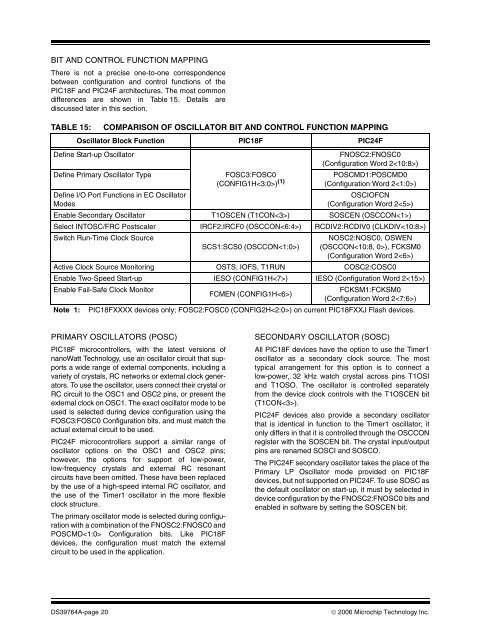
BIT AND CONTROL FUNCTION MAPPINGThere is not a precise one-<strong>to</strong>-one correspondencebetween configuration and control functions of the<strong>PIC18F</strong> and <strong>PIC24F</strong> architectures. The most commondifferences are shown in Table 15. Details arediscussed later in this section.TABLE 15:COMPARISON OF OSCILLATOR BIT AND CONTROL FUNCTION MAPPINGOscilla<strong>to</strong>r Block Function <strong>PIC18F</strong> <strong>PIC24F</strong>Define Start-up Oscilla<strong>to</strong>rDefine Primary Oscilla<strong>to</strong>r TypeDefine I/O Port Functions in EC Oscilla<strong>to</strong>rModesFOSC3:FOSC0(CONFIG1H) (1)FNOSC2:FNOSC0(Configuration Word 2)POSCMD1:POSCMD0(Configuration Word 2)OSCIOFCN(Configuration Word 2)Enable Secondary Oscilla<strong>to</strong>r T1OSCEN (T1CON) SOSCEN (OSCCON)Select INTOSC/FRC Postscaler IRCF2:IRCF0 (OSCCON) RCDIV2:RCDIV0 (CLKDIV)Switch Run-Time Clock SourceSCS1:SCS0 (OSCCON)NOSC2:NOSC0, OSWEN(OSCCON), FCKSM0(Configuration Word 2)Active Clock Source Moni<strong>to</strong>ring OSTS, IOFS, T1RUN COSC2:COSC0Enable Two-Speed Start-up IESO (CONFIG1H) IESO (Configuration Word 2)Enable Fail-Safe Clock Moni<strong>to</strong>rFCKSM1:FCKSM0FCMEN (CONFIG1H)(Configuration Word 2)Note 1: <strong>PIC18F</strong>XXXX devices only; FOSC2:FOSC0 (CONFIG2H) on current <strong>PIC18F</strong>XXJ Flash devices.PRIMARY OSCILLATORS (POSC)<strong>PIC18F</strong> microcontrollers, with the latest versions ofnanoWatt Technology, use an oscilla<strong>to</strong>r circuit that supportsa wide range of external components, including avariety of crystals, RC networks or external clock genera<strong>to</strong>rs.To use the oscilla<strong>to</strong>r, users connect their crystal orRC circuit <strong>to</strong> the OSC1 and OSC2 pins, or present theexternal clock on OSC1. The exact oscilla<strong>to</strong>r mode <strong>to</strong> beused is selected during device configuration using theFOSC3:FOSC0 Configuration bits, and must match theactual external circuit <strong>to</strong> be used.<strong>PIC24F</strong> microcontrollers support a similar range ofoscilla<strong>to</strong>r options on the OSC1 and OSC2 pins;however, the options for support of low-power,low-frequency crystals and external RC resonantcircuits have been omitted. These have been replacedby the use of a high-speed internal RC oscilla<strong>to</strong>r, andthe use of the Timer1 oscilla<strong>to</strong>r in the more flexibleclock structure.The primary oscilla<strong>to</strong>r mode is selected during configurationwith a combination of the FNOSC2:FNOSC0 andPOSCMD Configuration bits. Like <strong>PIC18F</strong>devices, the configuration must match the externalcircuit <strong>to</strong> be used in the application.SECONDARY OSCILLATOR (SOSC)All <strong>PIC18F</strong> devices have the option <strong>to</strong> use the Timer1oscilla<strong>to</strong>r as a secondary clock source. The mosttypical arrangement for this option is <strong>to</strong> connect alow-power, 32 kHz watch crystal across pins T1OSIand T1OSO. The oscilla<strong>to</strong>r is controlled separatelyfrom the device clock controls with the T1OSCEN bit(T1CON).<strong>PIC24F</strong> devices also provide a secondary oscilla<strong>to</strong>rthat is identical in function <strong>to</strong> the Timer1 oscilla<strong>to</strong>r; i<strong>to</strong>nly differs in that it is controlled through the OSCCONregister with the SOSCEN bit. The crystal input/outputpins are renamed SOSCI and SOSCO.The <strong>PIC24F</strong> secondary oscilla<strong>to</strong>r takes the place of thePrimary LP Oscilla<strong>to</strong>r mode provided on <strong>PIC18F</strong>devices, but not supported on <strong>PIC24F</strong>. To use SOSC asthe default oscilla<strong>to</strong>r on start-up, it must by selected indevice configuration by the FNOSC2:FNOSC0 bits andenabled in software by setting the SOSCEN bit.DS39764A-page 20© 2006 <strong>Microchip</strong> Technology Inc.
INTERNAL RC OSCILLATORS (INTOSC/FRCAND INTRC/LPRC)The internal oscilla<strong>to</strong>rs for <strong>PIC18F</strong> devices withnanoWatt Technology and <strong>PIC24F</strong> devices are virtuallyidentical, except in name. Both feature two independentinternal oscilla<strong>to</strong>rs, an efficient 31 kHz oscilla<strong>to</strong>r and anaccurate, high-speed 8 MHz oscilla<strong>to</strong>r. Both architecturesuse a configurable postscaler, driven by the 8 MHzsource, <strong>to</strong> provide a range of clock frequencies, from31 kHz <strong>to</strong> 4 MHz (as well as the undivided 8 MHzoutput). Both architectures allow software selection fromthe 31 kHz or 8 MHz oscilla<strong>to</strong>rs <strong>to</strong> provide the 31 kHzsource for various system features. Both clock systemspermit tuning of the 8 MHz source through a nominalrange of ±12%.The differences here are minor. For <strong>PIC18F</strong> devices,the internal 31 kHz and 8 MHz sources are generallyreferred <strong>to</strong> as INTOSC and INTRC. For <strong>PIC24F</strong>devices, they are known as the Fast RC (FRC) andLow-Power RC (LPRC) oscilla<strong>to</strong>rs. INTOSC/FRC tuningis accomplished with 5 tuning bits (TUN4:TUN0) in<strong>PIC18F</strong> devices; <strong>PIC24F</strong> devices use 6 tuning bits(TUN5:TUN0) for finer resolution. Finally, the defaultvalue on Reset for the 8 MHz postscaler is 1 MHz for<strong>PIC18F</strong> devices and 4 MHz for <strong>PIC24F</strong> devices.PLL FREQUENCY MULTIPLIER<strong>PIC18F</strong> and <strong>PIC24F</strong> devices both support a 4x PLLfrequency multiplier for use with select clock sources.In all cases, the PLL provides a stable output only whenthe input frequency is between 4 and 10 MHz. Theoperation of the PLL differs substantially between thetwo architectures.For most <strong>PIC18F</strong> devices incorporating nanoWattTechnology, the PLL is au<strong>to</strong>matically enabled forspecific, primary oscilla<strong>to</strong>r configurations and is alwaysoperational. All devices can use the HS oscilla<strong>to</strong>r withthe PLL; select later devices also allow the use of thePLL with the EC mode. These are distinct primaryoscilla<strong>to</strong>r configurations. If the user wishes <strong>to</strong> disable thePLL, the device must be reprogrammed and reconfigured.If the internal oscilla<strong>to</strong>r block is selected as thedevice’s default oscilla<strong>to</strong>r, the PLL is made availablewhen the INTOSC postscaler is configured for an outpu<strong>to</strong>f 4 or 8 MHz. In these cases, the PLL can be selectivelyenabled under software control with the PLLEN controlbit (OSCTUN).For <strong>PIC24F</strong> devices, the PLL is always available undersoftware control. It is available for all primary oscilla<strong>to</strong>rmodes, as well as FRC or FRCDIV operation (as longas a postscaler output of at least 4 MHz is selected). Touse the PLL, it is only necessary <strong>to</strong> perform a clockswitch <strong>to</strong> one of the PLL Clock modes. Once a PLLmode is selected, the state of the PLL’s output stabilityis indicated by the flag bit, LOCK (OSCCON).When the bit is set, the PLL output is stable.CLOCK SWITCHINGClock switching differs significantly between <strong>PIC18F</strong>and <strong>PIC24F</strong> devices. Conceptually, both architectureshave three categories of oscilla<strong>to</strong>rs: primary (externalcomponents connected <strong>to</strong> OSC pins), secondary(external crystal connected <strong>to</strong> T1OSC or SOSC pins)and internal RC. <strong>PIC18F</strong> devices permit the definitionof one and only one primary oscilla<strong>to</strong>r type used duringdevice configuration. This is the oscilla<strong>to</strong>r that is alwaysused when on device power-up and Reset. Thereafter,the device can switch between primary, secondary andinternal oscilla<strong>to</strong>r sources, under software control, bywriting <strong>to</strong> the SCS1:SCS0 bits. Once a primaryoscilla<strong>to</strong>r is defined, it cannot be changed unless thedevice is reprogrammed.For <strong>PIC24F</strong> devices, any one of the three major clocksources can be configured as the default start-up oscilla<strong>to</strong>r;users are no longer confined <strong>to</strong> just the primaryoscilla<strong>to</strong>r sources. During run time, the device canswitch between any of the available oscilla<strong>to</strong>r modesunder software control. This means, that among otherthings, it is possible <strong>to</strong> switch between a Primary Clockmode and its PLL counterpart while the application isrunning. It is also possible <strong>to</strong> start the device using theTimer1 or LPRC oscilla<strong>to</strong>r, rather than switch <strong>to</strong> thosesources after Reset or power-up (as was required in<strong>PIC18F</strong> implementations of nanoWatt Technology). Infact, it is possible <strong>to</strong> completely disable the primaryoscilla<strong>to</strong>r source in <strong>PIC24F</strong> devices; something thatcannot be done on the <strong>PIC18F</strong> architecture.This increased flexibility makes clock switching on<strong>PIC24F</strong> devices a more complex sequence. The newoscilla<strong>to</strong>r is selected with the NOSC2:NOSC0 bits andby setting the Oscilla<strong>to</strong>r Switch Enable bit, OSWEN. Toprevent unintended changes, <strong>PIC24F</strong> devices also usean additional safety interlock that requires an unlocksequence <strong>to</strong> write each byte of the OSCCON register.<strong>PIC24F</strong> unlocks the high or low byte for one instructionafter two specific literals are written <strong>to</strong> the high or lowbyte of OSCCON. <strong>An</strong> instruction counter ensures theunlock sequence is performed within a maximumnumber of instructions and remains unlocked for oneinstruction cycle. Because these sequences are sotime critical, the unlock sequences are done with anassembly language routine. When the NOSC bitsmatch the COSC bits, or the OSWEN bit is clear, theclock switch has been completed successfully.Because the New Oscilla<strong>to</strong>r Select bits, NOSC, andOscilla<strong>to</strong>r Switch Enable bit, OSWEN (OSCCON),reside in opposite halves of OSCCON, two unlocksequences are needed <strong>to</strong> request a system clockswitch. For examples of the OSCCON unlocksequences, refer <strong>to</strong> the specific device data sheet.© 2006 <strong>Microchip</strong> Technology Inc. DS39764A-page 21