PIC18F to PIC24F Migration: An Overview - Microchip
PIC18F to PIC24F Migration: An Overview - Microchip
PIC18F to PIC24F Migration: An Overview - Microchip

Create successful ePaper yourself
Turn your PDF publications into a flip-book with our unique Google optimized e-Paper software.
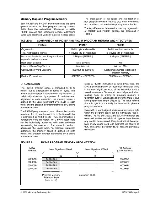
Memory Map and Program MemoryBoth <strong>PIC18F</strong> and <strong>PIC24F</strong> architectures use the samegeneral schema for their program memory spaces.Aside from the self-evident differences in width,<strong>PIC24F</strong> devices also incorporate a larger addressingrange and enhanced visibility features in data space.The organization of the space and the location ofnon-program memory features also differ somewhat,and must be considered when porting an application.The key differences between the memory organizationof <strong>PIC18F</strong> and <strong>PIC24F</strong> devices are presented inTable 6.TABLE 6:COMPARISON OF <strong>PIC18F</strong> AND <strong>PIC24F</strong> PROGRAM MEMORY ARCHITECTURESFeature <strong>PIC18F</strong> <strong>PIC24F</strong>Organization 16-bit, byte addressable 24-bit, word addressableTotal Addressable Range 4 Mbytes (22-bit magnitude) 16 Mbytes (24-bit magnitude)Maximum Available User Program Space 2 Mbytes (FFFFFh) 8 Mbytes (7FFFFFh)(upper boundary address)Boot Block Support Most devices NoInterrupt/Reset/Trap Vec<strong>to</strong>rs 00h, 08h, 18h 00h <strong>to</strong> 1FFhConfiguration Word Locations 300000h <strong>to</strong> 30000Fh Last 2 implemented locations inprogram memoryDevice ID Locations 3FFFFE and 3FFFFFh FF0000h and FF0002hORGANIZATIONThe <strong>PIC18F</strong> program space is organized as 16-bitwords, but is addressable in terms of bytes. Thismeans that the upper or lower byte of any word can beindividually addressed by a pointer. To maintain wordalignment for code execution, the memory space isaligned on the Least Significant Byte (LSB) of eachword, and the program counter increments by 2 duringnormal execution.The <strong>PIC24F</strong> program space has a different, but parallelstructure. It is physically organized as 24 bits wide, butis addressed as 16-bit words. Thus, an instruction isconsidered <strong>to</strong> be two words, not 3 bytes. Each wordcan be individually addressed with even addressesrepresenting the lower word of an instruction and oddaddresses the upper word. To maintain instructionalignment, the memory space is aligned on evenwords; the program counter increments by 2 duringnormal execution.Since a <strong>PIC24F</strong> instruction is three bytes wide, theMost Significant Byte of an instruction finds itself alonein the most significant word of the instruction as it iss<strong>to</strong>red in memory. To maintain word alignment whenreading from, or writing <strong>to</strong> program memory, a“phan<strong>to</strong>m byte” of 00h is added before the MSB <strong>to</strong> giveit the proper word length (Figure 2). The value reflectsthat this byte is not actually implemented in physicalprogram memory.Even with its word-aligned addressing, any single bytewithin the program space can be individually read orwritten. The <strong>PIC24F</strong> TBLRD and TBLWT commands areextended <strong>to</strong> allow an individual upper or lower byte ofany word <strong>to</strong> be accessed. Keep in mind that the upperbyte of any upper word (odd address) will always be00h, and cannot be written <strong>to</strong>, for reasons previouslydiscussed.FIGURE 2:<strong>PIC24F</strong> PROGRAM MEMORY ORGANIZATIONMSWAddressMost Significant WordLeast Significant WordPC Address(LSW Address)000001h000003h000005h000007h00000000000000000000000000000000231680000000h000002h000004h000006hProgram Memory‘Phan<strong>to</strong>m’ Byte(read as ‘0’)Instruction Width© 2006 <strong>Microchip</strong> Technology Inc. DS39764A-page 7