PIC18F to PIC24F Migration: An Overview - Microchip
PIC18F to PIC24F Migration: An Overview - Microchip
PIC18F to PIC24F Migration: An Overview - Microchip
Create successful ePaper yourself
Turn your PDF publications into a flip-book with our unique Google optimized e-Paper software.
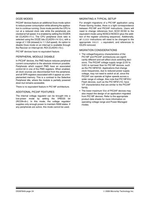
DOZE MODES<strong>PIC24F</strong> devices feature an additional Doze mode option<strong>to</strong> reduce power consumption while allowing the application<strong>to</strong> continue running. Doze mode permits the CPU <strong>to</strong>run at a reduced clock rate while the peripherals areclocked at full speed. It is enabled by setting the DOZENbit (CLKDIV). The CPU peripheral clock ratio isselected using the DOZE bits (CLKDIV), with arange of 1:128 (slowest) <strong>to</strong> 1:1 (full speed). <strong>An</strong> option <strong>to</strong>disable Doze mode on an interrupt is available throughthe Recover on Interrupt bit, ROI (CLKDIV).<strong>PIC18F</strong> devices have no equivalent feature.PERIPHERAL MODULE DISABLEIn <strong>PIC24F</strong> devices, the PMD feature reduces peripheralcurrent consumption <strong>to</strong> the absolute minimum possible.Peripherals which support PMD have an associatedcontrol bit in one of the PMD registers. When enabled,all clock sources are disconnected from the peripheral,and all SFR registers associated with it appear as unimplementedmemory. This is a contrast <strong>to</strong> the SelectivePeripheral Idle, where the module is partially powereddown but remains accessible.There is no equivalent feature in <strong>PIC18F</strong> architecture.ADDITIONAL <strong>PIC24F</strong> FEATURESThe internal voltage regula<strong>to</strong>r can be brought in<strong>to</strong> alow-power mode by setting the VREGS bit(RCON). In this mode, the voltage regula<strong>to</strong>rsupplies only enough power <strong>to</strong> maintain RAM states. Ifany peripherals are active, this mode cannot be used.MIGRATING A TYPICAL SETUPFor straight migrations of a <strong>PIC18F</strong> application usingPower-Saving modes, there is a tight correspondencebetween <strong>PIC18F</strong> and <strong>PIC24F</strong> instructions. Users willneed <strong>to</strong> change references from SCS1:SCS0 <strong>to</strong> theequivalent mode using NOSC2:NOSC0 (plus the additionof the register unlocking sequence). Additionally,all SLEEP instructions will need <strong>to</strong> be changed <strong>to</strong> theappropriate PWRSV n equivalent, and references <strong>to</strong>IDLEN removed.MIGRATION CONSIDERATIONS• The voltage/frequency characteristics of the<strong>PIC18F</strong> and <strong>PIC24F</strong> architectures are significantlydifferent and will affect clock switching decisions.The <strong>PIC24F</strong> voltage supply range (2.0V <strong>to</strong>3.6V) is narrower than for <strong>PIC18F</strong> devices, suchas the <strong>PIC18F</strong>8722. Applications that changeclock frequencies, due <strong>to</strong> reduced power supplyvoltage, may not need <strong>to</strong> switch at all, since the<strong>PIC24F</strong> can operate at higher speeds across awider range of voltage. Also note that <strong>PIC18F</strong>XXJFlash devices, such as the <strong>PIC18F</strong>87J10, haveV/F characteristics that are similar <strong>to</strong> the <strong>PIC24F</strong>family.• The lower maximum VDD of <strong>PIC24F</strong> devices mayalso impact the design of an application migratedfrom <strong>PIC18F</strong> devices. Refer <strong>to</strong> the appropriateproduct data sheets for more information onoperating voltage range and Power-Managedmodes.DS39764A-page 24© 2006 <strong>Microchip</strong> Technology Inc.


