PIC18F to PIC24F Migration: An Overview - Microchip
PIC18F to PIC24F Migration: An Overview - Microchip
PIC18F to PIC24F Migration: An Overview - Microchip
Create successful ePaper yourself
Turn your PDF publications into a flip-book with our unique Google optimized e-Paper software.
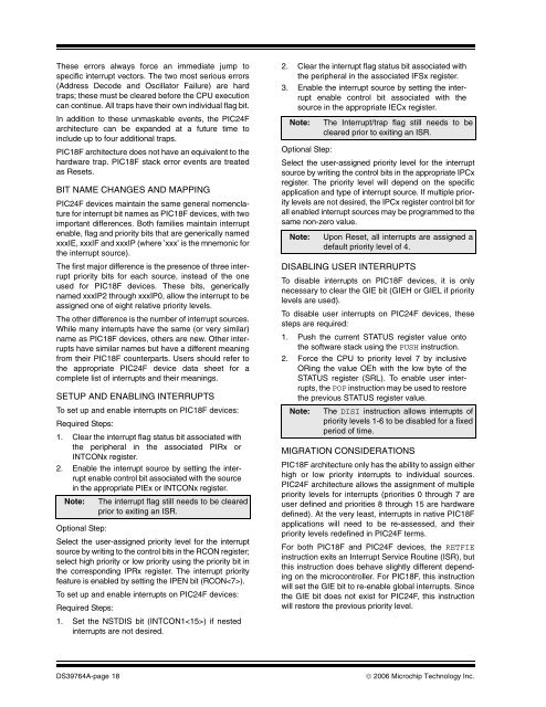
These errors always force an immediate jump <strong>to</strong>specific interrupt vec<strong>to</strong>rs. The two most serious errors(Address Decode and Oscilla<strong>to</strong>r Failure) are hardtraps; these must be cleared before the CPU executioncan continue. All traps have their own individual flag bit.In addition <strong>to</strong> these unmaskable events, the <strong>PIC24F</strong>architecture can be expanded at a future time <strong>to</strong>include up <strong>to</strong> four additional traps.<strong>PIC18F</strong> architecture does not have an equivalent <strong>to</strong> thehardware trap. <strong>PIC18F</strong> stack error events are treatedas Resets.BIT NAME CHANGES AND MAPPING<strong>PIC24F</strong> devices maintain the same general nomenclaturefor interrupt bit names as <strong>PIC18F</strong> devices, with twoimportant differences. Both families maintain interruptenable, flag and priority bits that are generically namedxxxIE, xxxIF and xxxIP (where ’xxx’ is the mnemonic forthe interrupt source).The first major difference is the presence of three interruptpriority bits for each source, instead of the oneused for <strong>PIC18F</strong> devices. These bits, genericallynamed xxxIP2 through xxxIP0, allow the interrupt <strong>to</strong> beassigned one of eight relative priority levels.The other difference is the number of interrupt sources.While many interrupts have the same (or very similar)name as <strong>PIC18F</strong> devices, others are new. Other interruptshave similar names but have a different meaningfrom their <strong>PIC18F</strong> counterparts. Users should refer <strong>to</strong>the appropriate <strong>PIC24F</strong> device data sheet for acomplete list of interrupts and their meanings.SETUP AND ENABLING INTERRUPTSTo set up and enable interrupts on <strong>PIC18F</strong> devices:Required Steps:1. Clear the interrupt flag status bit associated withthe peripheral in the associated PIRx orINTCONx register.2. Enable the interrupt source by setting the interruptenable control bit associated with the sourcein the appropriate PIEx or INTCONx register.Note: The interrupt flag still needs <strong>to</strong> be clearedprior <strong>to</strong> exiting an ISR.Optional Step:Select the user-assigned priority level for the interruptsource by writing <strong>to</strong> the control bits in the RCON register;select high priority or low priority using the priority bit inthe corresponding IPRx register. The interrupt priorityfeature is enabled by setting the IPEN bit (RCON).To set up and enable interrupts on <strong>PIC24F</strong> devices:Required Steps:1. Set the NSTDIS bit (INTCON1) if nestedinterrupts are not desired.2. Clear the interrupt flag status bit associated withthe peripheral in the associated IFSx register.3. Enable the interrupt source by setting the interruptenable control bit associated with thesource in the appropriate IECx register.Note:Optional Step:Select the user-assigned priority level for the interruptsource by writing the control bits in the appropriate IPCxregister. The priority level will depend on the specificapplication and type of interrupt source. If multiple prioritylevels are not desired, the IPCx register control bit forall enabled interrupt sources may be programmed <strong>to</strong> thesame non-zero value.Note:The Interrupt/trap flag still needs <strong>to</strong> becleared prior <strong>to</strong> exiting an ISR.Upon Reset, all interrupts are assigned adefault priority level of 4.DISABLING USER INTERRUPTSTo disable interrupts on <strong>PIC18F</strong> devices, it is onlynecessary <strong>to</strong> clear the GIE bit (GIEH or GIEL if prioritylevels are used).To disable user interrupts on <strong>PIC24F</strong> devices, thesesteps are required:1. Push the current STATUS register value on<strong>to</strong>the software stack using the PUSH instruction.2. Force the CPU <strong>to</strong> priority level 7 by inclusiveORing the value OEh with the low byte of theSTATUS register (SRL). To enable user interrupts,the POP instruction may be used <strong>to</strong> res<strong>to</strong>rethe previous STATUS register value.Note: The DISI instruction allows interrupts ofpriority levels 1-6 <strong>to</strong> be disabled for a fixedperiod of time.MIGRATION CONSIDERATIONS<strong>PIC18F</strong> architecture only has the ability <strong>to</strong> assign eitherhigh or low priority interrupts <strong>to</strong> individual sources.<strong>PIC24F</strong> architecture allows the assignment of multiplepriority levels for interrupts (priorities 0 through 7 areuser defined and priorities 8 through 15 are hardwaredefined). At the very least, interrupts in native <strong>PIC18F</strong>applications will need <strong>to</strong> be re-assessed, and theirpriority levels redefined in <strong>PIC24F</strong> terms.For both <strong>PIC18F</strong> and <strong>PIC24F</strong> devices, the RETFIEinstruction exits an Interrupt Service Routine (ISR), butthis instruction does behave slightly different dependingon the microcontroller. For <strong>PIC18F</strong>, this instructionwill set the GIE bit <strong>to</strong> re-enable global interrupts. Sincethe GIE bit does not exist for <strong>PIC24F</strong>, this instructionwill res<strong>to</strong>re the previous priority level.DS39764A-page 18© 2006 <strong>Microchip</strong> Technology Inc.


