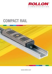
COMPACT RAIL (pdf; EN) - Rollon
COMPACT RAIL (pdf; EN) - Rollon
COMPACT RAIL (pdf; EN) - Rollon
- No tags were found...
You also want an ePaper? Increase the reach of your titles
YUMPU automatically turns print PDFs into web optimized ePapers that Google loves.
2 Technical dataTwo sliders under load moment M zIf an overhanging load acts in an application with two sliders per rail andthus causes an M z-moment in one direction, there are differing supportreactions with the two sliders. For this reason, an optimal arrangement ofdifferent slider configurations to reach the maximum load capacities mustbe achieved for the application. In practice this means, when using NTE-,NUE- or CS-sliders with 3 or 5 rollers, both sliders are installed rotatedby 180° so that the slider is always loaded on the side with the mostrollers (with NKE-sliders this is not possible due to the different racewaygeometry). For an even number of rollers this has no effect. The CD-sliderwith installation option from above or below cannot be installed due to theposition of the rollers in reference to the installation side therefore they areavailable in the configurations A and B (see fig. 18).CS-slider under load moment M zFCS-slider with 5 rollersnormal installation directionP1P2CS-slider with 5 rollersinstallation direction rotated by 180°Fig. 17CD-slider under load moment M zFCDW43-120 P1Configuration AP1P2CDW43-120Configuration BFig. 1810 www.rollon.com


