COMPACT RAIL (pdf; EN) - Rollon
COMPACT RAIL (pdf; EN) - Rollon
COMPACT RAIL (pdf; EN) - Rollon
- No tags were found...

Create successful ePaper yourself
Turn your PDF publications into a flip-book with our unique Google optimized e-Paper software.
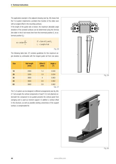
5 Technical instructionsThe application example in the adjacent drawing (see fig. 59) shows thatthe T+U-system implements a problem-free function of the slider evenwith an angled offset in the mounting surfaces.If the length of the guide rails is known, the maximum allowable angledeviation of the screwed surfaces can be determined using this formula(the slider in the U-rail moves here from the innermost position S 1to outermostposition S 2):αα = arctan S*LS* = Sum of S 1and S 2L = Length of railSFig. 58The following table (tab. 27) contains guidelines for this maximum angledeviation α, achievable with the longest guide rail from one piece.LSizeRail length[mm]Offset S[mm]Angle α[°]18 2000 1.4 0.04028 3200 1.9 0.03435 3600 4 0.063Fig. 5943 3600 3.9 0.06263 3600 3.9 0.062Tab. 27The T+U-system can be designed in different arrangements (see fig. 60).A T-rail accepts the vertical components of load P. A U-rail attached underneaththe component to be guided prevents the vertical panel fromswinging and is used as moment support. In addition a vertical offsetin the structure, as well as possible existing unevenness of the supportsurface, is compensated for.Fig. 6044 www.rollon.com