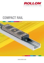
COMPACT RAIL (pdf; EN) - Rollon
COMPACT RAIL (pdf; EN) - Rollon
COMPACT RAIL (pdf; EN) - Rollon
- No tags were found...
Create successful ePaper yourself
Turn your PDF publications into a flip-book with our unique Google optimized e-Paper software.
Installation instructions 6General informationThe maximum available rail length in one piece is indicated in table 7 onpage 19. Longer lengths are achieved by joining two or more rails (joinedrails).<strong>Rollon</strong> then machines the rail ends at a right angle to the impact surfacesA A A A LLand marks them. Additional fixing screws are included with the delivery,which ensure a problem-free transition of the slider over the joints, if thefollowing installation procedures are followed. Two additional threaded holes(see fig. 114) are required in the load-bearing structure. The includedend fixing screws correspond to the installation screws for the rails forcylindrical counterbores (see pg. 60).The alignment fixture for aligning the rail joint can be ordered using theFig. 114designation given in the table (see pg. 33, tab. 19 and 20).Rail typeA[mm]Threaded hole(load-bearing structure)Screw typeL[mm]AlignmentfixtureT..., U...18 7 M48 AT18T..., U...28 8 M5 10 AT28T..., U...35 10 M6 13 AT35T..., U...43 11 M8 see pg. 34 16 AT43T..., U...63 8 M8 20 AT63K...43 11 M8 16 AK43K...63 8 M8 20 AK63Tab. 46www.rollon.com69


