Day and Night VS Air Handler Installation.pdf
Day and Night VS Air Handler Installation.pdf
Day and Night VS Air Handler Installation.pdf
You also want an ePaper? Increase the reach of your titles
YUMPU automatically turns print PDFs into web optimized ePapers that Google loves.
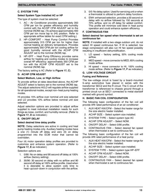
INSTALLATION INSTRUCTIONSC. SYSTEM TYPESelect System Type Installed AC or HPThe type of system must be selected:1. AC -- <strong>Air</strong> Conditioner provides approximately 350CFM per ton for greater efficiency <strong>and</strong> humiditycontrol with the AC/HP CFM ADJUST set to thenominal (NOM) tap. (To achieve approximately 400CFM per ton move tap to (HI) position. Refer toappropriate airflow tables for exact CFM setting.)2. HP--COMFORT -- Heat Pump Comfort Providesapproximately 315 CFM per ton for higher thannormal heating air delivery temperature. Providesapproximately 350 CFM per ton cooling airflow forgood humidity removal with the AC/HP CFMADJUST set to the nominal (NOM) tap.3. HP--EFF -- Heat Pump Efficiency provides sameairflow for heating <strong>and</strong> cooling modes to increaseoverall HP efficiency; approximately 350 CFM perton with the AC/HP CFM ADJUST set to thenominal (NOM) tap.The factory setting is AC (Refer to Figure 17, C).D. AC/HP CFM ADJUSTSelect Medium, Low, or High <strong>Air</strong>flowTo provide airflow at rates described above, the AC/HPADJUST select is factory set to the nominal (NOM) tap.The adjust selections HI/LO will regulate airflow suppliedfor all operational modes, except non--heat pump heatingmodes.HI provides 15% airflow over nominal unit size selected<strong>and</strong> LO provides 10% airflow below nominal unit sizeselected.Adjust selection options are provided to adjust airflowsupplied to meet individual installation needs for suchthings as noise, comfort, <strong>and</strong> humidity removal. (Refer toFigure 17, D as indicated.)E. ON/OFF DELAYSelect desired time delay profileNOTE: Delay selections are active in cooling <strong>and</strong> heatpump heating modes only. Auxiliary heating modes havea one (1) minute off delay <strong>and</strong> zero (0) on delayprogrammed into the ECM motor that cannot beoverridden.Four (4) motor operation delay profiles are provided tocustomize <strong>and</strong> enhance system operation. (Refer toFigure 17, E as indicated.)Selection options are:1. 0/90: No on delay <strong>and</strong> 90 second off delay at 100%airflow (factory setting).2. 30/90: 30 second on delay with no airflow <strong>and</strong> 90second off delay at 100% airflow profile. Used whenit is desirable to allow system coils time toheat--up/cool--down in conjunction with the airflow.Fan Coils: FVM2X, FVM4X3. 0/0: No delay option. Used for servicing unit or whena thermostat is utilized to perform delay functions.4. ENH: enhanced selection, provides a 30 second ondelay with no airflow followed by 150 seconds at70% airflow, <strong>and</strong> no off delay for added comfort.This profile will minimize cold blow in heat pumpoperation <strong>and</strong> could enhance system efficiency.F. CONTINUOUS FANSelect desired fan speed when thermostat is set oncontinuous fanNOTE: If installed with a two--stage outdoor unit, do notselect HI speed continuous fan. If HI is selected, lowstage compression will also run HI fan speed possiblyresulting in insufficient dehumidification.1. LO speed -- factory setting, 50% cooling modeairflow.2. MED speed -- move connector to MED, 65% coolingmode airflow.3. HI speed -- move connector to HI, 100% coolingmode airflow. (Refer to Figure 17, F as indicated.)G. LOW -VOLTAGE CIRCUITFusing <strong>and</strong> ReferenceThe low--voltage circuit is fused by a board--mounted5--amp automotive fuse placed in series with thetransformer SEC2 <strong>and</strong> the R circuit. The C circuit of thetransformer is referenced to chassis ground through aprinted circuit run at SEC1 connected to metal st<strong>and</strong>offmarked with ground symbol.H. BASIC FAN COIL CONFIGURATIONThe following basic configuration of the fan coil willprovide ARI rated performance of an air conditioner:1. AUX HEAT KW/CFM -- Select the heater range forthe size electric heater installed.2. AC/HP SIZE -- Select system size installed.3. SYSTEM TYPE -- Select system type AC4. AC/HP CFM ADJUST -- Select NOM.5. ON/OFF DELAY -- Select 0/90 profile.6. CONTINUOUS FAN -- Select desired fan speedwhen thermostat is set to continuous fan.The following basic configuration of the fan coil willprovide ARI rated performance of a heat pump:1. AUX HEAT KW/CFM -- Select the heater range forthe size electric heater installed.2. AC/HP SIZE -- Select system size installed.3. SYSTEM TYPE -- Select system type HP--EFF4. AC/HP CFM ADJUST -- Select NOM.5. ON/OFF DELAY -- Select 0/90 profile.6. CONTINUOUS FAN -- Select desired fan speedwhen thermostat is set to continuous fan.496 01 5001 02 Specifications are subject to change without notice13


