Day and Night VS Air Handler Installation.pdf
Day and Night VS Air Handler Installation.pdf
Day and Night VS Air Handler Installation.pdf

Create successful ePaper yourself
Turn your PDF publications into a flip-book with our unique Google optimized e-Paper software.
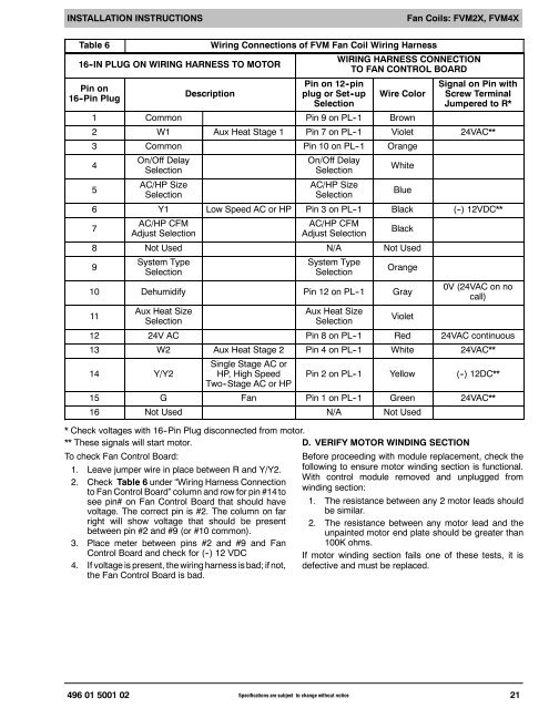
INSTALLATION INSTRUCTIONSFan Coils: FVM2X, FVM4XTable 616 -IN PLUG ON WIRING HARNESS TO MOTORPin on16 -Pin PlugDescriptionWiring Connections of FVM Fan Coil Wiring HarnessPinon12-pinplug or Set -upSelectionWIRING HARNESS CONNECTIONTO FAN CONTROL BOARDWire ColorSignal on Pin withScrew TerminalJumpered to R*1 Common Pin9onPL--1 Brown2 W1 Aux Heat Stage 1 Pin7onPL--1 Violet 24VAC**3 Common Pin10onPL--1 Orange45On/Off DelaySelectionAC/HP SizeSelectionOn/Off DelaySelectionAC/HP SizeSelectionWhite6 Y1 Low Speed AC or HP Pin3onPL--1 Black (--) 12VDC**7AC/HP CFMAdjust SelectionAC/HP CFMAdjust SelectionBlueBlack8 Not Used N/A Not Used9System TypeSelectionSystem TypeSelectionOrange10 Dehumidify Pin12onPL--1 Gray11Aux Heat SizeSelectionAux Heat SizeSelectionViolet0V (24VAC on nocall)12 24V AC Pin8onPL--1 Red 24VAC continuous13 W2 Aux Heat Stage 2 Pin4onPL--1 White 24VAC**14 Y/Y2Single Stage AC orHP, High Speed Pin2onPL--1 Yellow (--) 12DC**Two--Stage AC or HP15 G Fan Pin1onPL--1 Green 24VAC**16 Not Used N/A Not Used* Check voltages with 16--Pin Plug disconnected from motor.** These signals will start motor.D. VERIFY MOTOR WINDING SECTIONTo check Fan Control Board:1. Leave jumper wire in place between R <strong>and</strong> Y/Y2.2. Check Table 6 under “Wiring Harness Connectionto Fan Control Board” column <strong>and</strong> row for pin #14 tosee pin# on Fan Control Board that should havevoltage. The correct pin is #2. The column on farright will show voltage that should be presentbetween pin #2 <strong>and</strong> #9 (or #10 common).3. Place meter between pins #2 <strong>and</strong> #9 <strong>and</strong> FanControl Board <strong>and</strong> check for (--) 12 VDC4. If voltage is present, the wiring harness is bad; if not,the Fan Control Board is bad.Before proceeding with module replacement, check thefollowing to ensure motor winding section is functional.With control module removed <strong>and</strong> unplugged fromwinding section:1. The resistance between any 2 motor leads shouldbe similar.2. The resistance between any motor lead <strong>and</strong> theunpainted motor end plate should be greater than100K ohms.If motor winding section fails one of these tests, it isdefective <strong>and</strong> must be replaced.496 01 5001 02 Specifications are subject to change without notice21