Day and Night VS Air Handler Installation.pdf
Day and Night VS Air Handler Installation.pdf
Day and Night VS Air Handler Installation.pdf

Create successful ePaper yourself
Turn your PDF publications into a flip-book with our unique Google optimized e-Paper software.
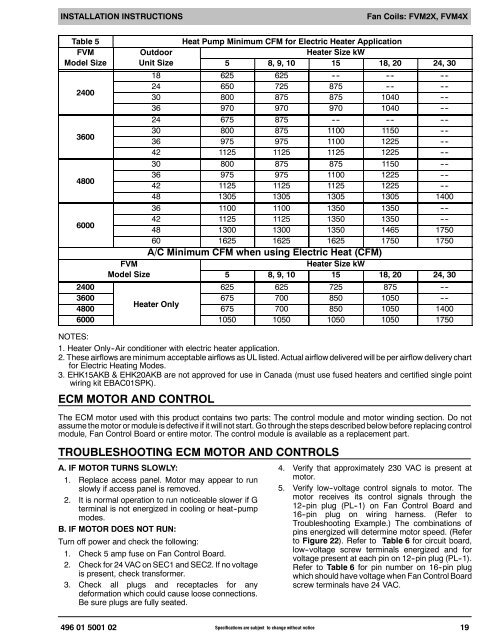
INSTALLATION INSTRUCTIONSFan Coils: FVM2X, FVM4XTable 5FVMModel Size2400360048006000FVMModel SizeOutdoorUnit SizeHeat Pump Minimum CFM for Electric Heater ApplicationHeater Size kW5 8, 9, 10 15 18, 20 24, 3018 625 625 -- -- -- -- -- --24 650 725 875 -- -- -- --30 800 875 875 1040 -- --36 970 970 970 1040 -- --24 675 875 -- -- -- -- -- --30 800 875 1100 1150 -- --36 975 975 1100 1225 -- --42 1125 1125 1125 1225 -- --30 800 875 875 1150 -- --36 975 975 1100 1225 -- --42 1125 1125 1125 1225 -- --48 1305 1305 1305 1305 140036 1100 1100 1350 1350 -- --42 1125 1125 1350 1350 -- --48 1300 1300 1350 1465 175060 1625 1625 1625 1750 1750A/C Minimum CFM when using Electric Heat (CFM)Heater Size kW5 8, 9, 10 15 18, 20 24, 30625 625 725 875 -- --24003600 675 700 850 1050 -- --Heater Only4800 675 700 850 1050 14006000 1050 1050 1050 1050 1750NOTES:1. Heater Only--<strong>Air</strong> conditioner with electric heater application.2. These airflows are minimum acceptable airflows as UL listed. Actual airflow delivered will be per airflow delivery chartfor Electric Heating Modes.3. EHK15AKB & EHK20AKB are not approved for use in Canada (must use fused heaters <strong>and</strong> certified single pointwiring kit EBAC01SPK).ECM MOTOR AND CONTROLThe ECM motor used with this product contains two parts: The control module <strong>and</strong> motor winding section. Do notassume the motor or module is defective if it will not start. Go through the steps described below before replacing controlmodule, Fan Control Board or entire motor. The control module is available as a replacement part.TROUBLESHOOTING ECM MOTOR AND CONTROLSA. IF MOTOR TURNS SLOWLY:1. Replace access panel. Motor may appear to runslowly if access panel is removed.2. It is normal operation to run noticeable slower if Gterminal is not energized in cooling or heat--pumpmodes.B. IF MOTOR DOES NOT RUN:Turn off power <strong>and</strong> check the following:1. Check 5 amp fuse on Fan Control Board.2. Check for 24 VAC on SEC1 <strong>and</strong> SEC2. If no voltageis present, check transformer.3. Check all plugs <strong>and</strong> receptacles for anydeformation which could cause loose connections.Be sure plugs are fully seated.4. Verify that approximately 230 VAC is present atmotor.5. Verify low--voltage control signals to motor. Themotor receives its control signals through the12--pin plug (PL--1) on Fan Control Board <strong>and</strong>16--pin plug on wiring harness. (Refer toTroubleshooting Example.) The combinations ofpins energized will determine motor speed. (Referto Figure 22). Refer to Table 6 for circuit board,low--voltage screw terminals energized <strong>and</strong> forvoltage present at each pin on 12--pin plug (PL--1).Refer to Table 6 for pin number on 16--pin plugwhich should have voltage when Fan Control Boardscrew terminals have 24 VAC.496 01 5001 02 Specifications are subject to change without notice19