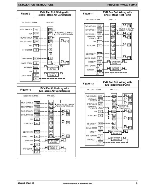
INSTALLATION INSTRUCTIONSELECTRICAL CONNECTIONSOn units with a factory installed disconnect with pull--outremoved, service <strong>and</strong> maintenance can be safelyperformed on only the load side of the control package.NOTE: Before proceeding with electrical connections,make certain that supply voltage, frequency, phase, <strong>and</strong>circuit ampacity are as specified on the unit rating plate.See unit wiring label for proper field high <strong>and</strong> low voltagewiring. Make all electrical connections in accordance withthe NEC <strong>and</strong> any local codes or ordinances that mayapply. Use copper wire only. The unit must have aseparate branch electric circuit with a field--supplieddisconnect switch located within sight from, <strong>and</strong> readilyaccessible from the unit.! WARNINGELECTRICAL SHOCK or UNIT DAMAGE HAZARDFailure to follow this warning could result in personalinjury or death.Turn off the main (remote) disconnect device beforeworking on incoming (field) wiring .Incoming (field) wires on the line side of the disconnectfound in the fan coil unit remain live, evenwhen the pull -out is removed. Service <strong>and</strong> maintenanceto incoming (field) wiring cannot be performeduntil the main disconnect switch (remoteto the unit) is turned off.! WARNINGELECTRICAL SHOCK or UNIT DAMAGE HAZARDFailure to follow this warning could result in personalinjury, death, <strong>and</strong>/or unit damage.If a disconnect switch is to be mounted on unit, selecta location where drill <strong>and</strong> fasteners will notcontact electrical or refrigeration components.A. LINE VOLTAGE CONNECTIONSIf unit contains an electric heater, remove <strong>and</strong> discardpower plug from fan coil <strong>and</strong> connect male plug fromheater to female plug from unit wiring harness. (Refer toElectric Heater <strong>Installation</strong> Instructions.) For units withoutelectric heat:1. Connect 208/230V power leads from fielddisconnect to yellow <strong>and</strong> black stripped leads.2. Connect ground wire to unit ground lug.Check all factory wiring per unit wiring diagram <strong>and</strong>inspect factory wiring connections to be sure none wereloosened in transit or installation.Fan Coils: FVM2X, FVM4XB. 24V CONTROL SYSTEMControl System Connections to Fan Control BoardRefer to unit wiring instructions for recommended wiringprocedures. Use 18 AWG color--coded, insulated (35 ˚Cminimum) wires to make the low--voltage connectionsbetween the thermostat, the unit, <strong>and</strong> the outdoorequipment. If the thermostat is located more than 100 feetfrom the unit (as measured along the low voltage wire),use 16 AWG color--coded, insulated (35 ˚C minimum)wire. Fan Control Board is circuited for single--stageheater operation. When additional heater staging isdesired using outdoor thermostats of Heat Staging,remove Jumper J2 on Fan Control Board to enablestaging.All wiring must be NEC Class 1 <strong>and</strong> must be separatedfrom incoming power leads. Refer to outdoor unit wiringinstructions for additional wiring recommendations.Connect low--voltage leads to thermostat <strong>and</strong> outdoorunit (refer to Figure 9, Figure 10, Figure 11, Figure 12).C. HEAT STAGINGHeat Staging OptionHeat Staging of the electric heat package is possiblewhen the FVM is installed as a part of a single--stage heatpump system using a two--stage programmablethermostat, or capable zoning control <strong>and</strong> <strong>and</strong> one (1) ofthe following electric heat packages:Relay heaters EHK10AKN, EHK10AKB, EHK15AK(F,B),EHK18AHN, EHK20AK(F,B) EHK25AHCF, orEHK30AHCF.Complete system low--voltage wiring as shown inFigure 9, Figure 10, Figure 11, Figure 12.NOTE: Where local codes require thermostat wiring berouted through conduit or raceways, splices can be madeinside the fan coil unit. All wiring must be NEC Class 1 <strong>and</strong>must be separated from incoming power leads.A factory--authorized disconnect kit is available forinstallation of 5 kW through 10 kW applications. Whenelectric heat package with circuit breakers are installed,the circuit breaker can be used as a disconnect.D. MANUFACTURED HOUSINGIn manufactured housing applications, the Code ofFederal Regulations, Title 24, Chapter XX, Part 3280.714requires that supplemental electric heat be locked out atoutdoor temperatures above 40 ˚F. except for a heatpump defrost cycle. In some applications, an outdoorthermostat may be required. Refer to thermostatinstructions for details.8 Specifications are subject to change without notice496 01 5001 02
INSTALLATION INSTRUCTIONSFan Coils: FVM2X, FVM4XFigure 9FVM Fan Coil Wiring withsingle -stage <strong>Air</strong> ConditionerFigure 11FVM Fan Coil Wiring withsingle -stage Heat PumpINDOOR CONTROLFAN COILINDOOR CONTROLFAN COILHEAT STAGE 2N/AHEAT STAGE 1O/W2Y1/W2W/W1W2Y1W1REMOVE J2 JUMPERFOR HEAT STAGINGR<strong>VS</strong> COOLINGHEAT STAGE 3HEAT STAGE 2HEAT/COOLSTAGE 1O/W2Y1/W2W/W1Y/Y2OW2W1Y/Y2OREMOVE J2 JUMPERFOR HEAT STAGINGW2YCOOL STAGE 1Y/Y2Y/Y2YFANGGFANGG24 VAC HOTRRR24 VAC HOTRRY1ODEHUMIDIFYDHUMHDEHUMIDIFYDHUMH24 VAC COMMCCC24 VAC COMMHUMIDIFYN/AOUTDOORCHUMBS1CHUMIDIFIER(24 VAC)OUTDOORSENSORCHUMIDIFYR<strong>VS</strong> HEATINGOUTDOORHUMBS1S2HUMIDIFIER(24 VAC)OUTDOORSENSORS2Figure 10FVM Fan Coil wiring withtwo -stage <strong>Air</strong> ConditioningFigure 12INDOOR CONTROLFVM Fan Coil wiring withtwo -stage Heat PumpFAN COILINDOOR CONTROLFAN COILR<strong>VS</strong> COOLINGO/W2OOHEAT STAGE 2HEAT STAGE 1COOL STAGE 1O/W2W/W1Y1/W2W2W1Y1REMOVE J2 JUMPERFOR HEAT STAGINGYHEAT/COOLSTAGE 1HEAT STAGE 3HEAT/COOLSTAGE 2FANY1/ W2W/W1Y/Y2GY1W1W2Y/Y2YW2REMOVE J2JUMPER FORHEAT STAGINGY2COOL STAGE 2Y/Y2Y/Y2Y224 VAC HOTRGFANGGRR24 VAC HOTRRRDEHUMIDIFYDHUMHO24 VAC COMMCCCDEHUMIDIFY24 VAC COMMHUMIDIFYN/AOUTDOORDHUMCHUMBS1HCHUMIDIFIER(24 VAC)OUTDOORSENSORCHUMIDIFYR<strong>VS</strong> HEATINGOUTDOORHUMBS1S2HUMIDIFIER(24 VAC)OUTDOORSENSORS2496 01 5001 02 Specifications are subject to change without notice9