Day and Night VS Air Handler Installation.pdf
Day and Night VS Air Handler Installation.pdf
Day and Night VS Air Handler Installation.pdf

You also want an ePaper? Increase the reach of your titles
YUMPU automatically turns print PDFs into web optimized ePapers that Google loves.
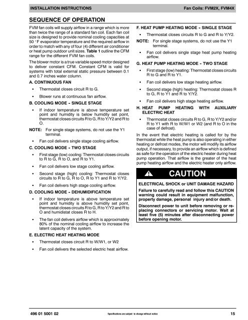
INSTALLATION INSTRUCTIONSSEQUENCE OF OPERATIONFVM fan coils will supply airflow in a range which is morethan twice the range of a st<strong>and</strong>ard fan coil. Each fan coilsize is designed to provide nominal cooling capacities at50 _F evaporator temperature <strong>and</strong> the required airflow inorder to match with any of four (4) different air conditioneror heat pump outdoor unit sizes. Table 1 outline the CFMrange for the different FVM fan coils.The blower motor is a true variable speed motor designedto deliver constant CFM. Constant CFM is valid forsystems with total external static pressure between 0.1<strong>and</strong> 0.7 inches water column.A. CONTINUOUS FANS Thermostat closes circuit R to G.S Blower runs at continuous fan airflow.B. COOLING MODE - SINGLE STAGES If indoor temperature is above temperature setpoint <strong>and</strong> humidity is below humidity set point,thermostat closes circuits R to G, R to Y/Y2 <strong>and</strong> R toO.NOTE: For single stage systems, do not use the Y1terminal.S Fan coil delivers single stage cooling airflow.C. COOLING MODE - TWO STAGES First stage (low) cooling: Thermostat closes circuitsto R to G, R to O, <strong>and</strong> R to Y1.SSFan coil delivers low stage cooling airflow.Second stage (high) cooling: Thermostat closescircuits to R to G, R to O, R to Y1 <strong>and</strong> R to Y/Y2.S Fan coil delivers high stage cooling airflow.D. COOLING MODE - DEHUMIDIFICATIONS If indoor temperature is above temperature setpoint <strong>and</strong> humidity is above humidity set point,thermostat closes circuits R to G, R to Y/Y2 <strong>and</strong> R toO <strong>and</strong> humidistat closes R to H.S The fan coil delivers airflow which is approximately80% of the nominal cooling airflow to increase thelatent capacity of the system.E. ELECTRIC HEAT HEATING MODES Thermostat closes circuit R to W/W1, or W2SFan coil delivers the selected electric heat airflow.Fan Coils: FVM2X, FVM4XF. HEAT PUMP HEATING MODE - SINGLE STAGES Thermostat closes circuits R to G <strong>and</strong> R to Y/Y2.NOTE: For single stage systems, do not use the Y1terminal.S Fan coil delivers single stage heat pump heatingairflow.G. HEAT PUMP HEATING MODE - TWO STAGES First stage (low) heating: Thermostat closes circuitsR to G <strong>and</strong> R to Y1.SSFan coil delivers low stage heating airflow.Second stage (high) heating: Thermostat closes Rto G, R to Y1 <strong>and</strong> R to Y/Y2.S Fan coil delivers high stage heating airflow.H. HEAT PUMP HEATING WITH AUXILIARYELECTRIC HEATS Thermostat closes circuits R to G, R to Y/Y2 <strong>and</strong>/orRtoY1withRtoW/W1orW2(<strong>and</strong>RtoOinthecase of defrost).In the event that electric heating is called for by thethermostat while the heat pump is also operating in eitherheating or defrost modes, the motor will modify its airflowoutput, if necessary, to provide an airflow which is definedas safe for the operation of the electric heater during heatpump operation. That airflow is the greater of the heatpump heating airflow <strong>and</strong> the electric heater only airflow.! CAUTIONELECTRICAL SHOCK or UNIT DAMAGE HAZARDFailure to carefully read <strong>and</strong> follow this CAUTIONwarning could result in equipment malfunction,property damage, personal injury <strong>and</strong>/or death.Disconnect power to unit before removing or replacingconnectors or servicing motor. Wait atleast five (5) minutes after disconnecting powerbefore opening motor.496 01 5001 02 Specifications are subject to change without notice15