Day and Night VS Air Handler Installation.pdf
Day and Night VS Air Handler Installation.pdf
Day and Night VS Air Handler Installation.pdf

You also want an ePaper? Increase the reach of your titles
YUMPU automatically turns print PDFs into web optimized ePapers that Google loves.
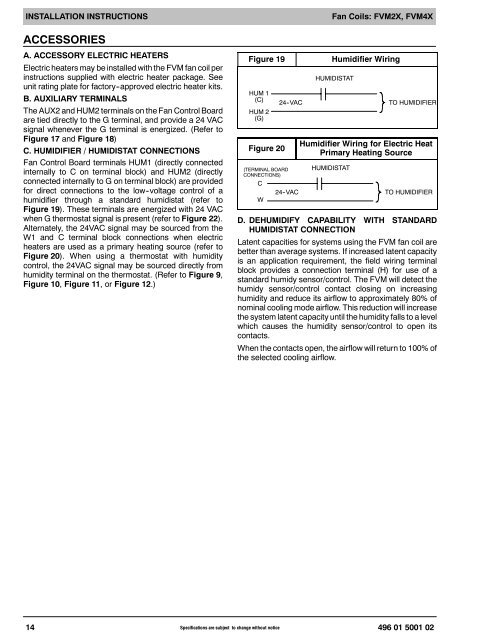
INSTALLATION INSTRUCTIONSFan Coils: FVM2X, FVM4XACCESSORIESA. ACCESSORY ELECTRIC HEATERSElectric heaters may be installed with the FVM fan coil perinstructions supplied with electric heater package. Seeunit rating plate for factory--approved electric heater kits.B. AUXILIARY TERMINALSThe AUX2 <strong>and</strong> HUM2 terminals on the Fan Control Boardare tied directly to the G terminal, <strong>and</strong> provide a 24 VACsignal whenever the G terminal is energized. (Refer toFigure 17 <strong>and</strong> Figure 18)C. HUMIDIFIER / HUMIDISTAT CONNECTIONSFan Control Board terminals HUM1 (directly connectedinternally to C on terminal block) <strong>and</strong> HUM2 (directlyconnected internally to G on terminal block) are providedfor direct connections to the low--voltage control of ahumidifier through a st<strong>and</strong>ard humidistat (refer toFigure 19). These terminals are energized with 24 VACwhen G thermostat signal is present (refer to Figure 22).Alternately, the 24VAC signal may be sourced from theW1 <strong>and</strong> C terminal block connections when electricheaters are used as a primary heating source (refer toFigure 20). When using a thermostat with humiditycontrol, the 24VAC signal may be sourced directly fromhumidity terminal on the thermostat. (Refer to Figure 9,Figure 10, Figure 11, orFigure 12.)Figure 19HUM 1(C)HUM 2(G)Figure 2024 -VAC(TERMINAL BOARDCONNECTIONS)C24 -VACWHumidifier WiringHUMIDISTATTO HUMIDIFIERHumidifier Wiring for Electric HeatPrimary Heating SourceHUMIDISTATTO HUMIDIFIERD. DEHUMIDIFY CAPABILITY WITH STANDARDHUMIDISTAT CONNECTIONLatent capacities for systems using the FVM fan coil arebetter than average systems. If increased latent capacityis an application requirement, the field wiring terminalblock provides a connection terminal (H) for use of ast<strong>and</strong>ard humidy sensor/control. The FVM will detect thehumidy sensor/control contact closing on increasinghumidity <strong>and</strong> reduce its airflow to approximately 80% ofnominal cooling mode airflow. This reduction will increasethe system latent capacity until the humidity falls to a levelwhich causes the humidity sensor/control to open itscontacts.When the contacts open, the airflow will return to 100% ofthe selected cooling airflow.14 Specifications are subject to change without notice496 01 5001 02