NX-700/700H
NX-700/700H
NX-700/700H
- No tags were found...

You also want an ePaper? Increase the reach of your titles
YUMPU automatically turns print PDFs into web optimized ePapers that Google loves.
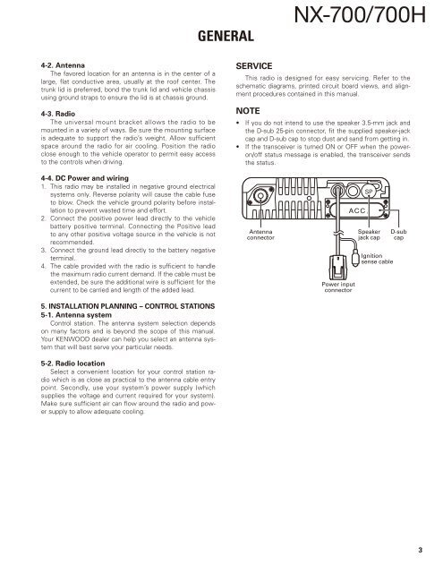
GENERAL<strong>NX</strong>-<strong>700</strong>/<strong>700</strong>H4-2. AntennaThe favored location for an antenna is in the center of alarge, flat conductive area, usually at the roof center. Thetrunk lid is preferred, bond the trunk lid and vehicle chassisusing ground straps to ensure the lid is at chassis ground.4-3. RadioThe universal mount bracket allows the radio to bemounted in a variety of ways. Be sure the mounting surfaceis adequate to support the radio’s weight. Allow sufficientspace around the radio for air cooling. Position the radioclose enough to the vehicle operator to permit easy accessto the controls when driving.SERVICEThis radio is designed for easy servicing. Refer to theschematic diagrams, printed circuit board views, and alignmentprocedures contained in this manual.NOTE• If you do not intend to use the speaker 3.5-mm jack andthe D-sub 25-pin connector, fit the supplied speaker-jackcap and D-sub cap to stop dust and sand from getting in.• If the transceiver is turned ON or OFF when the poweron/offstatus message is enabled, the transceiver sendsthe status.4-4. DC Power and wiring1. This radio may be installed in negative ground electricalsystems only. Reverse polarity will cause the cable fuseto blow. Check the vehicle ground polarity before installationto prevent wasted time and effort.2. Connect the positive power lead directly to the vehiclebattery positive terminal. Connecting the Positive leadto any other positive voltage source in the vehicle is notrecommended.3. Connect the ground lead directly to the battery negativeterminal.4. The cable provided with the radio is sufficient to handlethe maximum radio current demand. If the cable must beextended, be sure the additional wire is sufficient for thecurrent to be carried and length of the added lead.5. INSTALLATION PLANNING – CONTROL STATIONS5-1. Antenna systemControl station. The antenna system selection dependson many factors and is beyond the scope of this manual.Your KENWOOD dealer can help you select an antenna systemthat will best serve your particular needs.5-2. Radio locationSelect a convenient location for your control station radiowhich is as close as practical to the antenna cable entrypoint. Secondly, use your system’s power supply (whichsupplies the voltage and current required for your system).Make sure sufficient air can flow around the radio and powersupply to allow adequate cooling.AntennaconnectorPower inputconnectorSpeakerjack capIgnitionsense cableD-subcap3