LM384 5W Audio Power Amplifier
LM384 5W Audio Power Amplifier
LM384 5W Audio Power Amplifier

Create successful ePaper yourself
Turn your PDF publications into a flip-book with our unique Google optimized e-Paper software.
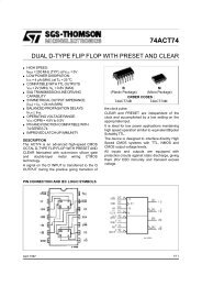
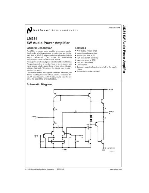
<strong>LM384</strong><strong>5W</strong> <strong>Audio</strong> <strong>Power</strong> <strong>Amplifier</strong>General DescriptionThe <strong>LM384</strong> is a power audio amplifier for consumer application.In order to hold system cost to a minimum, gain is internallyfixed at 34 dB. A unique input stage allows inputs to beground referenced. The output is automaticallyself-centering to one half the supply voltage.The output is short-circuit proof with internal thermal limiting.The package outline is standard dual-in-line. A copper leadframe is used with the center three pins on either side comprisinga heat sink. This makes the device easy to use instandard p-c layout.Uses include simple phonograph amplifiers, intercoms, linedrivers, teaching machine outputs, alarms, ultrasonic drivers,TV sound systems, AM-FM radio, sound projector systems,etc. See AN-69 for circuit details.Schematic DiagramFebruary 1995Featuresn Wide supply voltage rangen Low quiescent power drainn Voltage gain fixed at 50n High peak current capabilityn Input referenced to GNDn High input impedancen Low distortionn Quiescent output voltage is at one half of the supplyvoltagen Standard dual-in-line package<strong>LM384</strong> <strong>5W</strong> <strong>Audio</strong> <strong>Power</strong> <strong>Amplifier</strong>DS007843-3© 1999 National Semiconductor Corporation DS007843 www.national.com
Absolute Maximum Ratings (Note 1)If Military/Aerospace specified devices are required,please contact the National Semiconductor Sales Office/Distributors for availability and specifications.Supply Voltage28VPeak Current 1.3A<strong>Power</strong> Dissipation (See (Notes 4, 5)) 1.67WInput Voltage±0.5VStorage Temperature−65˚C to +150˚COperating TemperatureLead Temperature(Soldering, 10 sec.)Thermal Resistanceθ JC0˚C to +70˚C260˚C30˚C/W79˚C/Wθ JANote 1: Absolute Maximum Ratings indicate limits beyond which damage tothe device may occur. Operating Ratings indicate conditions for which the deviceis functional, but do not guarantee specific performance limits.Electrical Characteristics (Note 2)Symbol Parameter Conditions Min Typ Max UnitsZ IN Input Resistance 150 kΩI BIAS Bias Current Inputs Floating 100 nAA V Gain 40 50 60 V/VP OUT Output <strong>Power</strong> THD = 10%, R L=8Ω 5 5.5 WI Q Quiescent Supply Current 8.5 25 mAV OUT Q Quiescent Output Voltage 11 VBW Bandwidth P OUT= 2W, R L= 8Ω 450 kHzV + Supply Voltage 12 26 VI SC Short Circuit Current (Note 6) 1.3 APSRR RTO <strong>Power</strong> Supply Rejection Ratio 31 dB(Note 3) )THD Total Harmonic Distortion P OUT= 4W, R L= 8Ω 0.25 1.0 %Note 2: V + = 22V and T A = 25˚C operating with a Staver V7 heat sink for 30 seconds.Note 3: Rejection ratio referred to the output with C BYPASS = 5 µF, freq = 120 Hz.Note 4: The maximum junction temperature of the <strong>LM384</strong> is 150˚C.Note 5: The package is to be derated at 15˚C/W junction to heat sink pins.Note 6: Output is fully protected against a shorted speaker condition at all voltages up to 22V.Heat Sink DimensionsStaver “V7” Heat SinkStaver Company41 Saxon Ave.P.O. Drawer HBay Shore, N.Y.Tel: (516) 666-8000DS007843-4www.national.com 2
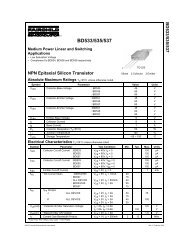
Typical Performance CharacteristicsDevice Dissipation vsAmbient TemperatureThermal Resistance vsSquare InchesSupply Decoupling vsFrequencyDS007843-10DS007843-11DS007843-12Total Harmonic Distortionvs Output <strong>Power</strong>Output Voltage Gain vsFrequencyTotal Harmonic Distortionvs FrequencyDS007843-13DS007843-14DS007843-15<strong>Power</strong> Supply Current vsSupply VoltageDevice Dissipation vsOutput <strong>Power</strong> — 16Ω LoadDevice Dissipation vsOutput <strong>Power</strong> — 8Ω LoadDS007843-16DS007843-17DS007843-183www.national.com
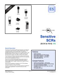
Typical Performance Characteristics (Continued)Device Dissipation vsOutput <strong>Power</strong> — 4Ω LoadBlock and Connection DiagramsDS007843-19Dual-In-Line PackageDS007843-1DS007843-2Note 7: Heatsink PinsTop ViewOrder Number <strong>LM384</strong>NSee NS Package Number N14Awww.national.com 4
Typical ApplicationsTypical <strong>5W</strong> <strong>Amplifier</strong>DS007843-6Bridge <strong>Amplifier</strong>DS007843-7IntercomDS007843-8*For stability with high current loads5www.national.com
Typical Applications (Continued)Phase Shift OscillatorDS007843-9www.national.com 6
Physical Dimensions inches (millimeters) unless otherwise noted<strong>LM384</strong> <strong>5W</strong> <strong>Audio</strong> <strong>Power</strong> <strong>Amplifier</strong>Molded Dual-In-Line Package (N)Order Number <strong>LM384</strong>NNS Package Number N14ALIFE SUPPORT POLICYNATIONAL’S PRODUCTS ARE NOT AUTHORIZED FOR USE AS CRITICAL COMPONENTS IN LIFE SUPPORTDEVICES OR SYSTEMS WITHOUT THE EXPRESS WRITTEN APPROVAL OF THE PRESIDENT AND GENERALCOUNSEL OF NATIONAL SEMICONDUCTOR CORPORATION. As used herein:1. Life support devices or systems are devices orsystems which, (a) are intended for surgical implantinto the body, or (b) support or sustain life, andwhose failure to perform when properly used inaccordance with instructions for use provided in thelabeling, can be reasonably expected to result in asignificant injury to the user.2. A critical component is any component of a lifesupport device or system whose failure to performcan be reasonably expected to cause the failure ofthe life support device or system, or to affect itssafety or effectiveness.National SemiconductorCorporationAmericasTel: 1-800-272-9959Fax: 1-800-737-7018Email: support@nsc.comwww.national.comNational SemiconductorEuropeFax: +49 (0) 1 80-530 85 86Email: europe.support@nsc.comDeutsch Tel: +49 (0) 1 80-530 85 85English Tel: +49 (0) 1 80-532 78 32Français Tel: +49 (0) 1 80-532 93 58Italiano Tel: +49 (0) 1 80-534 16 80National SemiconductorAsia Pacific CustomerResponse GroupTel: 65-2544466Fax: 65-2504466Email: sea.support@nsc.comNational SemiconductorJapan Ltd.Tel: 81-3-5639-7560Fax: 81-3-5639-7507National does not assume any responsibility for use of any circuitry described, no circuit patent licenses are implied and National reserves the right at any time without notice to change said circuitry and specifications.