TMS320F206 Digital Signal Processor (Rev. A) - Futurlec
TMS320F206 Digital Signal Processor (Rev. A) - Futurlec
TMS320F206 Digital Signal Processor (Rev. A) - Futurlec

You also want an ePaper? Increase the reach of your titles
YUMPU automatically turns print PDFs into web optimized ePapers that Google loves.
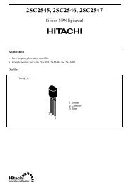
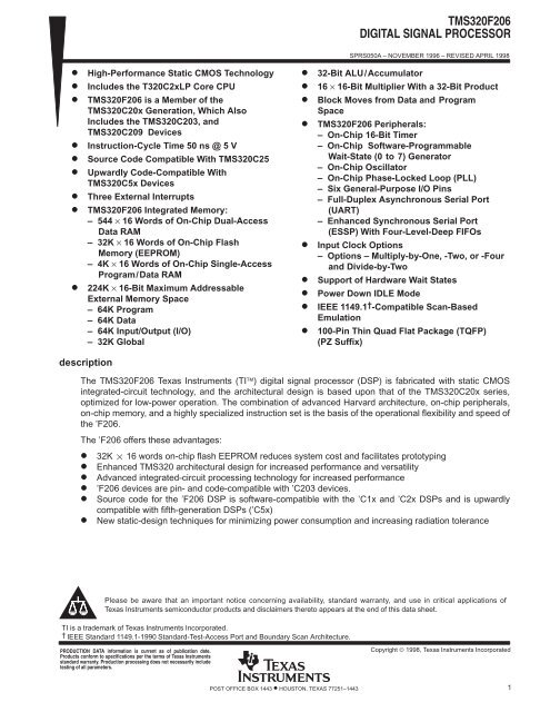
<strong>TMS320F206</strong>DIGITAL SIGNAL PROCESSORSPRS050A – NOVEMBER 1996 – REVISED APRIL 1998High-Performance Static CMOS TechnologyIncludes the T320C2xLP Core CPU<strong>TMS320F206</strong> is a Member of theTMS320C20x Generation, Which AlsoIncludes the TMS320C203, andTMS320C209 DevicesInstruction-Cycle Time 50 ns @ 5 VSource Code Compatible With TMS320C25Upwardly Code-Compatible WithTMS320C5x DevicesThree External Interrupts<strong>TMS320F206</strong> Integrated Memory:– 544 × 16 Words of On-Chip Dual-AccessData RAM– 32K × 16 Words of On-Chip FlashMemory (EEPROM)– 4K × 16 Words of On-Chip Single-AccessProgram/Data RAM224K × 16-Bit Maximum AddressableExternal Memory Space– 64K Program– 64K Data– 64K Input/Output (I/O)– 32K Global32-Bit ALU/Accumulator16 × 16-Bit Multiplier With a 32-Bit ProductBlock Moves from Data and ProgramSpace<strong>TMS320F206</strong> Peripherals:– On-Chip 16-Bit Timer– On-Chip Software-ProgrammableWait-State (0 to 7) Generator– On-Chip Oscillator– On-Chip Phase-Locked Loop (PLL)– Six General-Purpose I/O Pins– Full-Duplex Asynchronous Serial Port(UART)– Enhanced Synchronous Serial Port(ESSP) With Four-Level-Deep FIFOsInput Clock Options– Options – Multiply-by-One, -Two, or -Fourand Divide-by-TwoSupport of Hardware Wait StatesPower Down IDLE ModeIEEE 1149.1 † -Compatible Scan-BasedEmulation100-Pin Thin Quad Flat Package (TQFP)(PZ Suffix)descriptionThe <strong>TMS320F206</strong> Texas Instruments (TI) digital signal processor (DSP) is fabricated with static CMOSintegrated-circuit technology, and the architectural design is based upon that of the TMS320C20x series,optimized for low-power operation. The combination of advanced Harvard architecture, on-chip peripherals,on-chip memory, and a highly specialized instruction set is the basis of the operational flexibility and speed ofthe ’F206.The ’F206 offers these advantages: 32K 16 words on-chip flash EEPROM reduces system cost and facilitates prototyping Enhanced TMS320 architectural design for increased performance and versatility Advanced integrated-circuit processing technology for increased performance ’F206 devices are pin- and code-compatible with ’C203 devices. Source code for the ’F206 DSP is software-compatible with the ’C1x and ’C2x DSPs and is upwardlycompatible with fifth-generation DSPs (’C5x)New static-design techniques for minimizing power consumption and increasing radiation tolerancePlease be aware that an important notice concerning availability, standard warranty, and use in critical applications ofTexas Instruments semiconductor products and disclaimers thereto appears at the end of this data sheet.TI is a trademark of Texas Instruments Incorporated.† IEEE Standard 1149.1-1990 Standard-Test-Access Port and Boundary Scan Architecture.PRODUCTION DATA information is current as of publication date.Products conform to specifications per the terms of Texas Instrumentsstandard warranty. Production processing does not necessarily includetesting of all parameters.Copyright © 1998, Texas Instruments IncorporatedPOST OFFICE BOX 1443 • HOUSTON, TEXAS 77251–14431
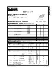
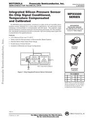
<strong>TMS320F206</strong>DIGITAL SIGNAL PROCESSORSPRS050A – NOVEMBER 1996 – REVISED APRIL 1998PZ PACKAGE( TOP VIEW )EMU0EMU1 / OFFTCKTRSTTDITMSTDOV SSCLKRFSRDRCLKXV SSFSXDXV DDTOUTTXV SSRXIO0IO1XFBIORS76777879808182838485868788899091929394959697989910075 74 73 72 71 70 69 68 67 66 65 64 63 62 61 60 59 58 57 56 55 54 53 52 511 2 3 4 5 6 7 8 95049484746454443424140393837363534333231302928272610 11 12 13 14 15 16 17 18 19 20 2122 23 24 25V DDREADYV SSR/WSTRBRDWEBRV SSD15D14D13D12V SSD11V DDD10D9D8D7V SSD6D5D4D3TESTMP / MCDIV1V CCPDIV 2HOLDAVIO2IO3PLL5VCLKIN/X2X1V SSCLKOUT1VCCPNMIHOLD / INT1INT2INT3VDDVDDVSSD0D1D2SSVVV DDA15A14A13A12SSA11A10A9A8A7VA6A5A4VA3A2A1A0VPSISDSSSDDSSSSTable 1 shows the capacity of on-chip RAM and ROM, the number of serial and parallel I/O ports, the executiontime of one machine cycle, and the type of package with total pin count of the <strong>TMS320F206</strong> device.DEVICEDATARAMTable 1. Characteristics of the <strong>TMS320F206</strong> <strong>Processor</strong>ON-CHIP MEMORYDATA/PROGROMFLASHEEPROMI/O PORTSPROG PROG SERIAL PARALLELPOWER CYCLE PACKAGESUPPLY TIME TYPE WITH(V) (ns) PIN COUNT<strong>TMS320F206</strong> 288 4K + 256 – 32K 2 64K 5 50 100-pin TQFP2 POST OFFICE BOX 1443 • HOUSTON, TEXAS 77251–1443
<strong>TMS320F206</strong>DIGITAL SIGNAL PROCESSORD15D14D13D12D11D10D9D8D7D6D5D4D3D2D1D0A15A14A13A12A11A10A9A8A7A6A5A4A3A2A1A0TERMINALNAME NO.4140393836343332312928272624232274737271696867666462616058575655TYPE†I/O/ZO/Z<strong>TMS320F206</strong> Terminal FunctionsDESCRIPTIONSPRS050A – NOVEMBER 1996 – REVISED APRIL 1998DATA AND ADDRESS BUSESParallel data bus D15 [most significant bit (MSB)] through D0 [least significant bit (LSB)]. D15–D0 areused to transfer data between the <strong>TMS320F206</strong> and external data / program memory or I / O devices.Placed in the high-impedance state when not outputting (R / W high) or RS when asserted. They go intothe high-impedance state when OFF is active low.Parallel address bus A15 (MSB) through A0 (LSB). A15–A0 are used to address external data / programmemory or I / O devices. These signals go into the high-impedance state when OFF is active low.MEMORY CONTROL SIGNALSPS 53 O/ZProgram-select signal. PS is always high unless low-level asserted for communicating to off-chip programspace. PS goes into the high-impedance state when OFF is active low.DS 51 O/ZData-select signal. DS is always high unless low-level asserted for communicating to off-chip programspace. DS goes into the high-impedance state when OFF is active low.IS 52 O/ZI / O space-select signal. IS is always high unless low-level asserted for communicating to I/O ports. ISgoes into the high-impedance state when OFF is active low.READY 49 IData-ready input. READY indicates that an external device is prepared for the bus transaction to becompleted. If the external device is not ready (READY low), the <strong>TMS320F206</strong> waits one cycle and checksREADY again. If READY is not used, it should be pulled high.R/W 47 O/ZRead/write signal. R / W indicates transfer direction when communicating with an external device. R/Wis normally in read mode (high), unless low level is asserted for performing a write operation. R / W goesinto the high-impedance state when OFF is active low.RD 45 O/ZRead-select indicates an active, external read cycle. RD is active on all external program, data, and I / Oreads. RD goes into the high-impedance state when OFF is active low. The function of the RD pin canbe programmed to provide an inverted R/W signal instead of RD. The FRDN bit (bit 15) in the PMSTregister controls this selection.† I = input, O = output, Z = high impedance, PWR = power, GND = groundPOST OFFICE BOX 1443 • HOUSTON, TEXAS 77251–14433
<strong>TMS320F206</strong>DIGITAL SIGNAL PROCESSORSPRS050A – NOVEMBER 1996 – REVISED APRIL 1998TERMINALNAMENO.TYPE†<strong>TMS320F206</strong> Terminal Functions (Continued)DESCRIPTIONMEMORY CONTROL SIGNALS (CONTINUED)WE 44 O/ZWrite enable. The falling edge of WE indicates that the device is driving the external data bus (D15 –D0). Datacan be latched by an external device on the rising edge of WE. WE is active on all external program, data, andI / O writes. WE goes into the high-impedance state when OFF is active low.STRB 46 O/ZStrobe signal. STRB is always high unless asserted low to indicate an external bus cycle. STRB goes into thehigh-impedance state when OFF is active low.MULTI-PROCESSING SIGNALSBR 43 O/ZBus-request signal. BR is asserted when a global data-memory access is initiated. BR goes into thehigh-impedance state when OFF is active low.HOLDA 6 O/ZHold-acknowledge signal. HOLDA indicates to the external circuitry that the processor is in a hold state andthat the address, data, and memory control lines are in the high-impedance state so that they are available tothe external circuitry for access of local memory. HOLDA goes into the high-impedance state when OFF isactive low.XF 98 O/ZExternal flag output (latched software-programmable signal). XF is used for signalling other processors inmultiprocessing configurations or as a general-purpose output pin. XF goes into the high-impedance statewhen OFF is active low.BIO 99 I Branch control input. When polled by the BIOZ instruction, if BIO is low, the <strong>TMS320F206</strong> executes a branch.IO0IO1IO2IO3969789I / O/ZRS 100 ISoftware-controlled input / output pins by way of the asynchronous serial-port control register (ASPCR). Atreset, IO0–IO3 are configured as inputs. These pins can be used as general-purpose input / output pins or ashandshake control for the UART. IO0 –IO3 go into the high-impedance state when OFF is active low.IO0 also functions as a frame-sync output when the synchronous serial port (SSP) is used in multichannelmode.INITIALIZATION, INTERRUPTS, AND RESET OPERATIONSReset input. RS causes the <strong>TMS320F206</strong> to terminate execution and forces the program counter to zero.When RS is brought high, execution begins at location 0 of program memory after 16 cycles. RS affects variousregisters and status bits.TEST 1 I Reserved input pin. TEST is connected to VSS for normal operation.MP/MC 2 INMI 17 IHOLD/INT1 18 IINT2INT31920TOUT 92 O/ZCLKOUT1 15 O/ZCLKIN/X2X11213IIOMicroprocessor/microcomputer-mode-select pin. If MP/MC is low, the on-chip flash memory is mapped intoprogram space. When MP/MC is high, the device accesses off-chip memory. This pin is only sampled at reset,and its value is latched into bit 0 of the PMST register.Nonmaskable interrupt. NMI is an external interrupt that cannot be masked by way of the interrupt-mode bit(INTM) or the interrupt mask register (IMR). When NMI is activated, the processor traps to the appropriatevector location. If NMI is not used, it should be pulled high.HOLD and INT1 share the same pin. Both are treated as interrupt signals. If the MODE bit is 0 in theinterrupt-control register (ICR), hold logic can be implemented in combination with the IDLE instruction insoftware. At reset, the MODE bit in ICR is zero, enabling the HOLD mode for the pin.External user interrupts. INT2 and INT3 are prioritized and maskable by the IMR and the INTM. INT2 and INT3can be polled and reset by way of the interrupt flag register (IFR).OSCILLATOR, PLL, AND TIMER SIGNALSTimer output. TOUT signals a pulse when the on-chip timer counts down past zero. The pulse is oneCLKOUT1-cycle wide. TOUT goes into the high-impedance state when OFF is active low.Master clock output signal. The CLKOUT1 signal cycles at the machine-cycle rate of the CPU. The internalmachine cycle is bounded by the rising edges of CLKOUT1. CLKOUT1 goes into the high-impedance statewhen OFF is active low.Input clock. CLKIN/X2 is the input clock to the device. As CLKIN, the pin operates as the external oscillatorclock input, and as X2, the pin operates as the internal oscillator input with X1 being the internal oscillatoroutput.† I = input, O = output, Z = high impedance, PWR = power, GND = ground4 POST OFFICE BOX 1443 • HOUSTON, TEXAS 77251–1443
<strong>TMS320F206</strong>DIGITAL SIGNAL PROCESSORTERMINALNAMENO.TYPE†<strong>TMS320F206</strong> Terminal Functions (Continued)DESCRIPTIONSPRS050A – NOVEMBER 1996 – REVISED APRIL 1998OSCILLATOR, PLL, AND TIMER SIGNALS (CONTINUED)DIV13DIV1 and DIV2 provide clock-mode inputs.IDIV25DIV1–DIV2 should not be changed unless the RS signal is active.PLL5V 10 I The <strong>TMS320F206</strong> is strictly a 5-V device. For this reason, the PLL5V pin should always be pulled high.SERIAL PORT AND UART SIGNALSCLKX 87 I/O/ZTransmit clock. CLKX is a clock signal for clocking data from the serial-port transmit shift register (XSR) to theDX data-transmit pin. The CLKX can be an input if the MCM bit in the synchronous serial-port control register(SSPCR) is set to 0. CLKX can also be driven by the device at one-half of the CLKOUT1 frequency whenMCM = 1. If the serial port is not being used, CLKX goes into the high-impedance state when OFF is activelow. Value at reset is as an input.CLKR 84 I/O/ZReceive-clock input. External clock signal for clocking data from the DR (data-receive) pin into the serial-portreceive shift register (RSR). CLKR must be present during serial-port transfers. If the serial port is not beingused, CLKR can be sampled as an input by the IN0 bit of the SSPCR. This pin also functions as a frame-syncoutput when the SSP is used in multichannel mode.FSR 85 I/O/ZFrame synchronization pulse for receive input. The falling edge of the FSR pulse initiates the data-receiveprocess, beginning the clocking of the RSR. FSR goes into the high-impedance state when OFF is active low.This pin also functions as a frame-sync output when the SSP is used in multichannel mode.FSX 89 I/O/ZFrame synchronization pulse for transmit input / ouput. The falling edge of the FSX pulse initiates thedata-transmit process, beginning the clocking of the serial-port transmit shift register (XSR). Following reset,FSX is an input. FSX can be selected by software to be an output when the TXM bit in the SSPCR is setto 1. FSX goes into the high-impedance state when OFF is active low.DR 86 I Serial-data receive input. Serial data is received in the receive shift register (RSR) through the DR pin.DX 90 O/ZSerial-port transmit output. Serial data is transmitted from the transmit shift register (XSR) through the DX pin.DX is in the high-impedance state when OFF is active low.TX 93 O/Z Asynchronous transmit data pin. TX is in the high-impedance state when OFF is active low.RX 95 I Asynchronous receive data pinTEST SIGNALSTRST 79 IIEEE Standard 1149.1 (JTAG) test reset. TRST, when driven high, gives the scan system control of theoperations of the device. If TRST is driven low, the device operates in its functional mode, and the test signalsare ignored.If the TRST pin is not driven, an external pulldown resistor must be used.TCK 78 IJTAG test clock. TCK is normally a free-running clock signal with a 50% duty cycle. The changes on thetest-access port (TAP) input signals (TMS and TDI) are clocked into the TAP controller, instruction register, orselected test-data register on the rising edge of TCK. Changes at the TAP output signal (TDO) occur on thefalling edge of TCK.TMS 81 I JTAG test-mode select. TMS is clocked into the TAP controller on the rising edge of TCK.TDI 80 I JTAG test-data input. TDI is clocked into the selected register (instruction or data) on a rising edge of TCK.TDO 82 O/ZJTAG test-data output. The contents of the selected register (instruction or data) are shifted out of TDO on thefalling edge of TCK. TDO is in the high-impedance state except when the scanning of data is in progress.EMU0 76 I/O/ZEmulator pin 0. When TRST is driven low, EMU0 must be high for activation of the OFF condition. When TRSTis driven high, EMU0 is used as an interrupt to or from the emulator system and is defined as an input / outputthrough the JTAG scan.EMU1/OFF 77 I/O/ZEmulator pin 1. Emulator pin 1 disables all outputs. When TRST is driven high, EMU1 / OFF is used as aninterrupt to or from the emulator system and is defined as an input / output through the JTAG scan. When TRSTis driven low, this pin is configured as OFF. EMU1 / OFF, when active low, puts all output drivers in thehigh-impedance state. Note that OFF is used exclusively for testing and emulation purposes (not formultiprocessing applications). Therefore, for the OFF condition, the following apply:TRST = 0EMU0 = 1EMU1/OFF = 0† I = input, O = output, Z = high impedance, PWR = power, GND = groundPOST OFFICE BOX 1443 • HOUSTON, TEXAS 77251–14435
<strong>TMS320F206</strong>DIGITAL SIGNAL PROCESSORSPRS050A – NOVEMBER 1996 – REVISED APRIL 1998TERMINALNAMEVCCPVDDNO.4167113550637591TYPE†<strong>TMS320F206</strong> Terminal Functions (Continued)SUPPLY PINSPWR VCCP must be connected directly to VDD .PWRPowerVSS1421253037424854GND Ground596570838894† I = input, O = output, Z = high impedance, PWR = power, GND = groundDESCRIPTION6 POST OFFICE BOX 1443 • HOUSTON, TEXAS 77251–1443
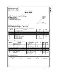
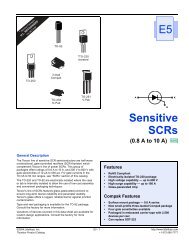
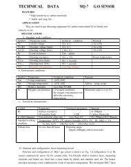
<strong>TMS320F206</strong>DIGITAL SIGNAL PROCESSORSPRS050A – NOVEMBER 1996 – REVISED APRIL 1998functional block diagram of the ’F206 internal hardwareDIV1DIV2ISDSPSR/WSTRBREADYBRXFHOLD †HOLDA †ControlX1CLKOUT1CLKIN/X216PCMUXNPARPARMSTACKProgram BusMUXData BusProgram BusRSRDWENMIStack 8 × 16MP/MCINT[1–3]3A15–A016MUX1616FLASH EEPROM(32K × 16)Program Control(PCTRL)161616D15–D016MUX16Data BusTOUTTimerTCRPRDTIMASPData Bus3ARP(3)3ARB(3)1631616AR0(16)AR1(16)AR2(16)AR3(16)AR4(16)AR5(16)AR6(16)AR7(16)9DP(9)97LSBfromIR16MUX161616 16MUX16TREG0(16)MultiplierADTR3ISCALE (0–16)PREG(32)TXRXI/O[0–3]4IOSRBRDMUX1632PSCALE (–6, 0, 1, 4)32 32DXCLKXFSXDRFSRCLKRSSPSSPCRSDTRReservedI/O-Mapped Registers16Memory MapRegisterIMR (16)IFR (16)GREG (16)Data/ProgSARAM(4K × 16)MUXARAU(16)MUXData/ProgDARAMB0 (256 × 16)MUX16MUXMUXDataDARAMB2 (32 × 16)B1 (256 × 16)16MUX32CALU(32)3232C ACCH(16) ACCL(16)32OSCALE (0–7)1616Program Bus161616NOTES: A. Symbol descriptions appear in Table 3.B. For clarity the data and program buses are shown as single buses although they include address and data bits.POST OFFICE BOX 1443 • HOUSTON, TEXAS 77251–14437
<strong>TMS320F206</strong>DIGITAL SIGNAL PROCESSORSPRS050A – NOVEMBER 1996 – REVISED APRIL 1998Table 2. Legend for the ’F206 Internal Hardware Functional Block DiagramSYMBOL NAME DESCRIPTIONACCARAUAUXREGSBRCCALUCNFGREGIMRIFRINTMAccumulatorAuxiliary RegisterArithmetic UnitAuxiliary Registers0–7Bus Request<strong>Signal</strong>CarryCentral ArithmeticLogic UnitOn-Chip RAMConfigurationControl BitGlobal MemoryAllocationRegisterInterrupt MaskRegisterInterrupt FlagRegisterInterrupt-Mode Bit32-bit register that stores the results and provides input for subsequent CALU operations. Also includes shiftand rotate capabilitiesAn unsigned, 16-bit arithmetic unit used to calculate indirect addresses using the auxiliary registers as inputsand outputsThese 16-bit registers are used as pointers to anywhere within the data space address range. They areoperated upon by the ARAU and are selected by the auxiliary register pointer (ARP). AR0 can also be usedas an index value for AR updates of more than one and as a compare value to AR.BR is asserted during access of the external global data memory space. READY is asserted to the devicewhen the global data memory is available for the bus transaction. BR can be used to extend the data memoryaddress space by up to 32K words.Register carry output from CALU. C is fed back into the CALU for extended arithmetic operation. The C bitresides in status register 1 (ST1), and can be tested in conditional instructions. C is also used in accumulatorshifts and rotates.32-bit-wide main arithmetic logic unit for the TMS320C2xx core. The CALU executes 32-bit operations in asingle machine cycle. CALU operates on data coming from ISCALE or PSCALE with data from ACC, andprovides status results to PCTRL.If set to 0, the reconfigurable data dual-access RAM (DARAM) block B0 is mapped to data space; otherwise,B0 is mapped to program space.GREG specifies the size of the global data memory space.IMR individually masks or enables the seven interrupts.The 7-bit IFR indicates that the <strong>TMS320F206</strong> has latched an interrupt from one of the seven maskableinterrupts.When INTM is set to 0, all unmasked interrupts are enabled. When INTM is set to 1, all maskable interruptsare disabled.INT# Interrupt Traps A total of 32 interrupts by way of hardware and/or software are available.ISCALEMPYMSTACKInput Data-ScalingShifterMultiplierMicro Stack16 to 32-bit barrel left-shifter. ISCALE shifts incoming 16-bit data 0 to16 positions left, relative to the 32-bitoutput within the fetch cycle; therefore, no cycle overhead is required for input scaling operations.16 × 16-bit multiplier to a 32-bit product. MPY executes multiplication in a single cycle. MPY operates eithersigned or unsigned 2s-complement arithmetic multiply.MSTACK provides temporary storage for the address of the next instruction to be fetched when programaddress-generation logic is used to generate sequential addresses in data space.MUX Multiplexer Multiplexes buses to a common inputNPARNext ProgramAddress RegisterNPAR holds the program address to be driven out on the PAB on the next cycle.OSCALEPARPCPCTRLOutputData-ScalingShifterProgram AddressRegisterProgram CounterProgramController16 to 32-bit barrel left-shifter. OSCALE shifts the 32-bit accumulator output 0 to 7 bits left for quantizationmanagement and outputs either the 16-bit high- or low-half of the shifted 32-bit data to the Data-Write DataBus (DWEB).PAR holds the address currently being driven on PAB for as many cycles as it takes to complete all memoryoperations scheduled for the current bus cycle.PC increments the value from NPAR to provide sequential addresses for instruction-fetching and sequentialdata-transfer operations.PCTRL decodes instruction, manages the pipeline, stores status, and decodes conditional operations.8 POST OFFICE BOX 1443 • HOUSTON, TEXAS 77251–1443
<strong>TMS320F206</strong>DIGITAL SIGNAL PROCESSORSPRS050A – NOVEMBER 1996 – REVISED APRIL 1998Table 2. Legend for the ’F206 Internal Hardware Functional Block Diagram (Continued)SYMBOL NAME DESCRIPTIONPMProductShift-ModeRegister BitsThese two bits identify which of the four product-shift modes (–6, 0, 1, 4) are used by PSCALE. PM residesin ST1. See Table 6.PREG Product Register 32-bit register holds results of 16 × 16 multiply.PSCALETREGSSPCRSDTRTCRPRDTIMUARTASPCRADTRIOSRProduct-ScalingShifterTemporaryRegisterSynchronousSerial-Port ControlRegisterSynchronousSerial-PortTransmit andReceive RegisterTimer-ControlRegisterTimer-PeriodRegisterTimer-CounterRegisterUniversalAsynchronousReceive/TransmitAsynchronousSerial-Port ControlRegisterAsynchronousData RegisterI / O StatusRegister0-, 1- or 4-bit left shift, or 6-bit right shift of multiplier product. The left-shift options are used to manage theadditional sign bits resulting from the 2s-complement multiply. The right-shift option is used to scale downthe number to manage overflow of product accumulation in the CALU. PSCALE resides in the path from the32-bit product shifter and from either the CALU or the Data-Write Data Bus (DWEB), and requires no cycleoverhead.16-bit register holds one of the operands for the multiply operations. TREG holds the dynamic shift countfor the LACT, ADDT, and SUBT instructions. TREG holds the dynamic bit position for the BITT instruction.SSPCR is the control register for selecting the serial port’s mode of operation.SDTR is the data-transmit and data-receive register.TCR contains the control bits that define the divide-down ratio, start / stop the timer, and reload the period.Also contained in TCR is the current count in the prescaler. Reset initializes the timer-divide-down ratioto 0 and starts the timer.PRD contains the 16-bit period that is loaded into the timer counter when the counter borrows or when thereload bit is activated. Reset initializes the PRD to 0xFFFF.TIM contains the current 16-bit count of the timer. Reset initializes the TIM to 0xFFFF.UART is the asynchronous serial port.ASPCR controls the asynchronous serial-port operation.Asynchronous data-transmit and data-receive registerIOSR detects current levels (and changes with inputs) on pins IO0 –IO3 and the status of UART.BRD Baud-Rate Divisor Used to set the baud rate of the UARTST0ST1IMRIFRSTACKStatus RegisterInterrupt MaskRegistersInterrupt FlagRegisterStackST0 and ST1 contain the status of various conditions and modes. These registers can be stored in andloaded from data memory, thereby allowing the status of the machine to be saved and restored.IMR individually masks or enables the seven interrupts.IFR indicates that the CPU has latched an interrupt pulse from one of the maskable interrupts.STACK is a block of memory used for storing return addresses for subroutines and interrupt-serviceroutines, or for storing data. The ’C20x stack is 16-bit wide and eight-level deep.POST OFFICE BOX 1443 • HOUSTON, TEXAS 77251–14439
<strong>TMS320F206</strong>DIGITAL SIGNAL PROCESSORSPRS050A – NOVEMBER 1996 – REVISED APRIL 1998architectural overviewThe ’F206 advanced Harvard-type architecture maximizes the processing power by maintaining two separatememory bus structures — program and data — for full-speed execution. The multiple buses allow data andinstructions to be read simultaneously. Instructions support data transfers between the two spaces. Thisarchitecture permits coefficients stored in program memory to be read in RAM, eliminating the need for aseparate coefficient ROM. This, coupled with a four-deep pipeline, allows the <strong>TMS320F206</strong> to execute mostinstructions in a single cycle.status and control registersTwo status registers, ST0 and ST1, contain the status of various conditions and modes. These registers canbe stored into data memory and loaded from data memory, thereby allowing the status of the machine to besaved and restored for subroutines.The load-status-register (LST) instruction is used to write to ST0 and ST1. The store-status-register (SST)instruction is used to read from ST0 and ST1 (except the INTM bit, which is not affected by the LST instruction).The individual bits of these registers can be set or cleared when using the SETC and CLRC instructions. Table 3and Table 4 show the organization of status registers ST0 and ST1, indicating all status and control bitscontained in each. Several bits in the status registers are reserved and read as logic 1s. Refer to Table 5 forstatus-register field definitions.Table 3. Status and Control Register Zero15 13 12 11 10 9 8 7 6 5 4 3 2 1 0ST0 ARP OV OVM 1 INTM DPTable 4. Status and Control Register One15 13 12 11 10 9 8 7 6 5 4 3 2 1 0ST1 ARB CNF TC SXM C 1 1 1 1 XF 1 1 PM10 POST OFFICE BOX 1443 • HOUSTON, TEXAS 77251–1443
<strong>TMS320F206</strong>DIGITAL SIGNAL PROCESSORSPRS050A – NOVEMBER 1996 – REVISED APRIL 1998status and control registers (continued)Table 5. Status Register Field DefinitionsFIELDARBARPCCNFDPINTMOVOVMPMSXMTCXFFUNCTIONAuxiliary register pointer buffer. Whenever the ARP is loaded, the old ARP value is copied to the ARB except during an LSTinstruction. When the ARB is loaded by an LST #1 instruction, the same value is also copied to the ARP.Auxiliary register pointer. ARP selects the AR to be used in indirect addressing. When the ARP is loaded, the old ARP valueis copied to the ARB register. ARP can be modified by memory-reference instructions when using indirect addressing, and bythe LARP, MAR, and LST instructions. The ARP is also loaded with the same value as ARB when an LST #1 instruction isexecuted.Carry Bit. C is set to 1 if the result of an addition generates a carry, or reset to 0 if the result of a subtraction generates a borrow.Otherwise, C is reset after an addition or set after a subtraction, except if the instruction is ADD or SUB with a 16-bit shift. Inthese cases, the ADD can only set and the SUB only reset the carry bit, but cannot affect it otherwise. The single-bit shift androtate instructions also affect C, as well as the SETC, CLRC, and LST #1 instructions. Branch instructions have been providedto branch on the status of C. C is set to 1 on a reset.On-chip RAM configuration-control bit. If CNF is set to 0, the reconfigurable data DARAM blocks are mapped to data space;otherwise, they are mapped to program space. The CNF can be modified by the SETC CNF, CLRC CNF, and LST #1 instructions.RS sets the CNF to 0.Data memory page pointer. The 9-bit DP register is concatenated with the seven LSBs of an instruction word to form a directmemory address of 16 bits. DP can be modified by the LST and LDP instructions.Interrupt-mode bit. When INTM is set to 0, all unmasked interrupts are enabled. When set to 1, all maskable interrupts aredisabled. INTM is set and reset by the SETC INTM and CLRC INTM instructions. RS also sets INTM. INTM has no effect onthe unmaskable RS and NMI interrupts. Note that INTM is unaffected by the LST instruction. This bit is set to 1 by reset. It isalso set to 1 when a maskable interrupt trap is taken.Overflow-flag bit. As a latched overflow signal, OV is set to 1 when overflow occurs in the ALU. Once an overflow occurs, theOV remains set until a reset, BCND/D on OV/NOV, or LST instructions clear OV.Overflow-mode bit. When OVM is set to 0, overflowed results overflow normally in the accumulator. When set to 1, theaccumulator is set to either its most positive or negative value upon encountering an overflow. The SETC and CLRCinstructions set and reset this bit, respectively. LST can also be used to modify the OVM.Product-shift mode. If these two bits are 00, the multiplier’s 32-bit product is loaded into the ALU with no shift. If PM = 01, thePREG output is left-shifted one place and loaded into the ALU, with the LSB zero-filled. If PM = 10, PREG output is left-shiftedby four bits and loaded into the ALU, with the LSBs zero-filled. PM = 11 produces a right shift of six bits, sign-extended. Notethat the PREG contents remain unchanged. The shift takes place when transferring the contents of the PREG to the ALU. PMis loaded by the SPM and LST #1 instructions. PM is cleared by RS.Sign-extension mode bit. SXM = 1 produces sign extension on data as it is passed into the accumulator through the scalingshifter. SXM = 0 suppresses sign extension. SXM does not affect the definitions of certain instructions; for example, the ADDSinstruction suppresses sign extension regardless of SXM. SXM is set by the SETC SXM and reset by the CLRC SXMinstructions, and can be loaded by the LST #1. SXM is set to 1 by reset.Test/control flag bit. TC is affected by the BIT, BITT, CMPR, LST #1, and NORM instructions. TC is set to a 1 if a bit tested byBIT or BITT is a 1, if a compare condition tested by CMPR exists between AR (ARP) and AR0, if the exclusive-OR functionof the two MSBs of the accumulator is true when tested by a NORM instruction. The conditional branch, call, and returninstructions can execute, based on the condition of TC.XF pin status bit. XF indicates the state of the XF pin, a general-purpose output pin. XF is set by the SETC XF and reset bythe CLRC XF instructions. XF is set to 1 by reset.central processing unitThe <strong>TMS320F206</strong> central processing unit (CPU) contains a 16-bit scaling shifter, a 16x16-bit parallel multiplier,a 32-bit central arithmetic logic unit (CALU), a 32-bit accumulator, and additional shifters at the outputs of boththe accumulator and the multiplier. This section describes the CPU components and their functions. Thefunctional block diagram shows the components of the CPU.POST OFFICE BOX 1443 • HOUSTON, TEXAS 77251–144311
<strong>TMS320F206</strong>DIGITAL SIGNAL PROCESSORSPRS050A – NOVEMBER 1996 – REVISED APRIL 1998input scaling shifterThe <strong>TMS320F206</strong> provides a scaling shifter with a 16-bit input connected to the data bus and a 32-bit outputconnected to the CALU. This shifter operates as part of the path of data coming from program or data spaceto the CALU and requires no cycle overhead. It is used to align the 16-bit data coming from memory to the 32-bitCALU. This is necessary for scaling arithmetic as well as aligning masks for logical operations.The scaling shifter produces a left shift of 0 to 16 on the input data. The LSBs of the output are filled with zeros;the MSBs can either be filled with zeros or sign-extended, depending upon the value of the SXM bit(sign-extension mode) of status register ST1. The shift count is specified by a constant embedded in theinstruction word or by a value in TREG. The shift count in the instruction allows for specific scaling or alignmentoperations specific to that point in the code. The TREG base shift allows the scaling factor to adapt to theperformance of the system.multiplierThe <strong>TMS320F206</strong> uses a 16x16-bit hardware multiplier that is capable of computing a signed or an unsigned32-bit product in a single machine cycle. All multiply instructions, except the MPYU (multiply unsigned)instruction, perform a signed-multiply operation. That is, two numbers being multiplied are treated as2s-complement numbers, and the result is a 32-bit 2s-complement number. There are two registers associatedwith the multiplier:16-bit temporary register (TREG) that holds one of the operands for the multiplier, and32-bit product register (PREG) that holds the product.Four product-shift modes (PM) are available at the PREG output (PSCALE). These shift modes are useful forperforming multiply/accumulate operations, performing fractional arithmetic, or justifying fractional products.The PM field of status register ST1 specifies the PM shift mode, as shown in Table 6.Table 6. PSCALE Product Shift ModesPM SHIFT DESCRIPTION00 no shift Product fed to CALU or data bus with no shift01 left 1 Removes the extra sign bit generated in a 2s-complement multiply to produce a Q31 product10 left 4 Removes the extra four sign bits generated in a 16x13 2s-complement multiply to a produce a Q31product when using the multiply by a 13-bit constant11 right 6 Scales the product to allow up to 128 product accumulation without the possibility of accumulator overflowThe product can be shifted one bit to compensate for the extra sign bit gained in multiplying two 16-bit2s-complement numbers (MPY). A four-bit shift is used in conjunction with the MPY instruction with a shortimmediate value (13 bits or less) to eliminate the four extra sign bits gained in multiplying a 16-bit number bya 13-bit number. Finally, the output of PREG can be right-shifted 6 bits to enable the execution of up to128 consecutive multiply/accumulates without the possibility of overflow.The LT (load TREG) instruction normally loads TREG to provide one operand (from the data bus), and the MPY(multiply) instruction provides the second operand (also from the data bus). A multiplication can also beperformed with a 13-bit immediate operand when using the MPY instruction. A product is then obtained everytwo cycles. For efficient implementation of multiple products, or multiple sums of products, the CPU providespipelining of the TREG load operation with certain CALU operations which use the PREG. These operationsinclude: load ACC with PREG (LTP); add PREG to ACC (LTA); add PREG to ACC and shift TREG input datato next address in data memory (LTD); and subtract PREG from ACC (LTS).12 POST OFFICE BOX 1443 • HOUSTON, TEXAS 77251–1443
<strong>TMS320F206</strong>DIGITAL SIGNAL PROCESSORSPRS050A – NOVEMBER 1996 – REVISED APRIL 1998multiplier (continued)Two multiply/accumulate instructions (MAC and MACD) fully utilize the computational bandwidth of themultiplier, allowing both operands to be processed simultaneously. The data for these operations can betransferred to the multiplier each cycle by way of the program and data buses. This facilitates single-cyclemultiply/accumulates when used with the repeat (RPT) instruction. In these instructions, the coefficientaddresses are generated by program address generation (PAGEN), while the data addresses are generatedby data address generation (DAGEN). This allows the repeated instruction to access the values sequentiallyfrom the coefficient table and step through the data in any of the indirect addressing modes.The MACD instruction, when repeated, supports filter constructs (weighted running averages) so that as thesum-of-products is executed, the sample data is shifted in memory to make room for the next sample and todiscard the oldest sample.The MPYU instruction performs an unsigned multiplication, which greatly facilitates extended-precisionarithmetic operations. The unsigned contents of TREG are multiplied by the unsigned contents of the addresseddata memory location, with the result placed in PREG. This allows the operands of greater than 16 bits to bebroken down into 16-bit words and processed separately to generate products of greater than 32 bits. TheSQRA (square/add) and SQRS (square/subtract) instructions pass the same value to both inputs of themultiplier for squaring a data memory value.After the multiplication of two 16-bit numbers, the 32-bit product is loaded into the 32-bit product register(PREG). The product from PREG can be transferred to the CALU or to data memory through the SPH (storeproduct high) and SPL (store product low) instructions. Note: the transfer of PREG to either the CALU or datamemory passes through the PSCALE shifter and is therefore, affected by the product-shift mode value definedby the PM bits in the ST1 register. This is important when saving PREG in an interrupt-service routine contextsave as the PSCALE shift effects cannot be modeled in the restore operation. PREG can be cleared byexecuting the MPY #0 instruction. The product register can be restored by loading the saved low half into TREGand executing a MPY #1 instruction. The high half is then loaded using the LPH instruction.central arithmetic logic unitThe <strong>TMS320F206</strong> CALU implements a wide range of arithmetic and logical functions, the majority of whichexecute in a single clock cycle. This ALU is referred to as “central” to differentiate it from a second ALU usedfor indirect address generation (called the ARAU). Once an operation is performed in the CALU, the result istransferred to the accumulator (ACC) where additional operations, such as shifting, can occur. Data that is inputto the CALU can be scaled by ISCALE when coming from one of the data buses (DRDB or PRDB) or scaledby PSCALE when coming from the multiplier.The CALU is a general-purpose arithmetic/logic unit that operates on 16-bit words taken from data memory orderived from immediate instructions. In addition to arithmetic operations, the CALU can perform Booleanoperations, facilitating the bit manipulation ability required for a high-speed controller. One input to the CALUis always provided from the accumulator, and the other input can be provided from the product register (PREG)of the multiplier or the output of the scaling shifter (that has been read from data memory or from the ACC). Afterthe CALU has performed the arithmetic or logical operation, the result is stored in the accumulator.The <strong>TMS320F206</strong> supports floating-point operations for applications requiring a large dynamic range. TheNORM (normalization) instruction is used to normalize fixed-point numbers contained in the accumulator byperforming left shifts. The four bits of the TREG define a variable shift through the scaling shifter for theLACT/ADDT/SUBT (load/add to/subtract from accumulator with shift specified by TREG) instructions. Theseinstructions are useful in floating-point arithmetic where denormalization of a number is required; that is,floating-point to fixed-point conversion. They are also useful in the implementation of automatic-gain control(AGC) at the input of a filter. The BITT (bit test) instruction provides testing of a single bit of a word in datamemory based on the value contained in the four LSBs of TREG.POST OFFICE BOX 1443 • HOUSTON, TEXAS 77251–144313
<strong>TMS320F206</strong>DIGITAL SIGNAL PROCESSORSPRS050A – NOVEMBER 1996 – REVISED APRIL 1998central arithmetic logic unit (continued)The CALU overflow saturation mode can be enabled/disabled by setting/resetting the OVM bit of ST0. Settingthe OVM status register bit selects the overflow saturation mode. When the CALU is in the overflow saturationmode and an overflow occurs, the overflow flag is set and the accumulator is loaded with either the most positiveor the most negative value representable in the accumulator, depending upon the direction of the overflow. Thevalue of the accumulator upon saturation is 07FFFFFFFh (positive) or 080000000h (negative). If the OVM(overflow mode) status register bit is reset and an overflow occurs, the overflowed results are loaded into theaccumulator without modification. (Note that logical operations cannot result in overflow.)The CALU can execute a variety of branch instructions that depend on the status of the CALU and accumulator.These instructions can be executed conditionally, based on various combinations of the associated status bits.For overflow management, these conditions include the OV (branch on overflow) and EQ (branch onaccumulator equal to zero). In addition, the BACC (branch-to-address in accumulator) instruction provides theability to branch to an address specified by the accumulator (computed goto). Bit test instructions (BIT andBITT), which do not affect the accumulator, allow the testing of a specified bit of a word in data memory.The CALU also has a carry bit (bit 9 of status register ST1) that facilitates efficient computation ofextended-precision products and additions or subtractions. The carry bit is also useful in overflow management.The carry bit is affected by the following operations:Additions to and subtractions from the accumulator:C = 0: When the result of a subtraction generates a borrow.When the result of an addition does not generate a carry. (Exception: When the ADD instruction isused with a shift of 16 and no carry is generated, the ADD instruction has no effect on C.)C = 1: When the result of an addition generates a carry.When the result of a subtraction does not generate a borrow. (Exception: When the SUB instructionis used with a shift of 16 and no borrow is generated, the SUB instruction has no effect on C.)Single-bit shifts and rotations of the accumulator value. During a left shift or rotation, the most significantbit of the accumulator is passed to C; during a right shift or rotation, the least significant bit is passed to C.Note: the carry bit is set to “1” on a hardware reset.The ADDC (add to accumulator with carry) and SUBB (subtract from accumulator with borrow) instructionsprovided, use the previous value of carry in their addition/subtraction operation.accumulatorThe 32-bit accumulator is the registered output of the CALU. It can be split into two 16-bit segments for storagein data memory. Shifters at the output of the accumulator provide a left shift of 0 to 7 places. This shift isperformed while the data is being transferred to the data bus for storage. The contents of the accumulatorremain unchanged. When the post-scaling shifter is used on the high word of the accumulator (bits 16–31), theMSBs are lost and the LSBs are filled with bits shifted in from the low word (bits 0–15). When the post-scalingshifter is used on the low word, the LSBs are zero-filled.The SFL and SFR (in-place one-bit shift to the left/right) instructions and the ROL and ROR (rotate to theleft/right) instructions implement shifting or rotating of the accumulator contents through the carry bit. The SXMbit affects the definition of the SFR (shift accumulator right) instruction. When SXM=1, SFR performs anarithmetic right shift, maintaining the sign of the accumulator data. When SXM=0, SFR performs a logical shift,shifting out the LSBs and shifting in a zero for the MSB. The SFL (shift accumulator left) instruction is not affectedby the SXM bit and behaves the same in both cases, shifting out the MSB and shifting in a zero. Repeat (RPT)instructions can be used with the shift and rotate instructions for multiple-bit shifts.14 POST OFFICE BOX 1443 • HOUSTON, TEXAS 77251–1443
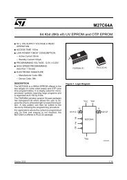
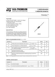
<strong>TMS320F206</strong>DIGITAL SIGNAL PROCESSORSPRS050A – NOVEMBER 1996 – REVISED APRIL 1998auxiliary registers and auxiliary-register arithmetic unit (ARAU)The ’F206 provides a register file containing eight auxiliary registers (AR0–AR7). The auxiliary registers areused for indirect addressing of the data memory or for temporary data storage. For indirect data memoryaddressing, the address of the desired memory location is placed into the selected auxiliary register. Theseregisters are referenced with a 3-bit auxiliary register pointer (ARP) that is loaded with a value from 0 through 7,designating AR0 through AR7, respectively. The auxiliary registers and the ARP can be loaded from datamemory, the ACC, the product register, or by an immediate operand defined in the instruction. The contents ofthese registers can also be stored in data memory or used as inputs to the CALU.The auxiliary register file (AR0–AR7) is connected to the auxiliary register arithmetic unit (ARAU). The ARAUcan autoindex the current auxiliary register while the data memory location is being addressed. Indexing eitherby ±1 or by the contents of the AR0 register can be performed. As a result, accessing tables of information doesnot require the CALU for address manipulation; therefore, the CALU is free for other operations in parallel.memoryThe ’F206 implements three separate address spaces for program memory, data memory, and I/O. Each spaceaccommodates a total of 64K 16-bit words. Within the 64K words of data space, the 256 to 32K words at thetop of the address range can be defined to be external global memory in increments of powers of two, asspecified by the contents of the global memory allocation register (GREG). Access to global memory isarbitrated using the global memory bus request (BR) signal.On the ’F206, the first 96 (0–5Fh) data memory locations are allocated for memory-mapped registers orreserved. This memory-mapped register space contains various control and status registers including those forthe CPU.The <strong>TMS320F206</strong> device includes 544 x 16 words of dual-access RAM (DARAM), 4K x 16 single-access RAM(SARAM), and 32K x 16 program flash memory. Table 7 shows the mapping of these memory blocks and theappropriate control bits and pins. Figure 1 shows the effects of the memory control pin MP/MC and the controlbit CNF on the mapping of the respective memory spaces to on-chip or off-chip. The PON and DON bits selectthe SARAM (4K) mapping in program, data, or both. See Table 8 for details of the PMST register, and PON andDON bits. At reset, these bits are 11, which selects the SARAM in program and data space. The SARAMaddresses are 0x800h in data and 0x8000h in program memory.At reset, if the MP/MC pin is held high, the device is in microprocessor mode and the program address branchesto 0x0000h (external program space). The MP/MC pin status is latched in the PMST register (bit 0). As long asthis bit remains high, the device is in microprocessor mode. PMST register bits can be read and modified insoftware. If bit 0 is cleared to 0, the device enters microcontroller mode and transfers control to the on-chip flashmemory at 0x0000.The on-chip data memory blocks B0 and B1 are 256 16 words each, and these blocks are mapped to dualaddress ranges within the ’F206 memory map. For example, when CNF = 0, B0 is mapped in data space ataddresses 0100–01FFh, and also at addresses 0200–02FFh. Corresponding addresses of the two ranges(0100h and 0200h, 0101h and 0201h, ...) access the same memory locations within B0. Similarly, whenCNF = 1, B0 is mapped in program space at addresses 0FE00–0FEFFh, and also at addresses0FF00–0FFFFh. The B1 block is always mapped in data space at addresses 0300–03FFh, and also at0400–04FFh.POST OFFICE BOX 1443 • HOUSTON, TEXAS 77251–144315
<strong>TMS320F206</strong>DIGITAL SIGNAL PROCESSORSPRS050A – NOVEMBER 1996 – REVISED APRIL 1998Hex0000003F00403FFF4000ProgramInterruptVectorsOn-Chip 16KFlash (0)(MP/MC = 0)External(MP/MC = 1)On-Chip 16KFlash (1)(MP/MC = 0)Hex0000005F0060007F008000FF0100DataMemory-MappedRegisters andReservedOn-ChipDARAM B2ReservedOn-ChipDARAM B0(CNF = 0)†Also Mapped at(0200–02FFh)Hex0000I/O Space7FFF8000External(MP/MC = 1)On-Chip SARAM4KInternal(PON = 1)01FF0200Reserved(CNF = 1)On-ChipDARAM B0(CNF = 0)Also Mapped at(0100–01FFh)ExternalI/O Space8FFF9000FDFFFE00FEFFFF00External(PON = 0)ExternalOn-ChipDARAM B0(CNF = 1)†Also Mapped at(0FF00–0FFFFh)External(CNF = 0)On-ChipDARAM B0(CNF = 1)Also Mapped at(0FE00–0FEFFh)02FF030003FF040004FF050007FF080017FF1800Reserved(CNF = 1)On-ChipDARAM B1Also Mapped at(0400–04FFh)On-ChipDARAM B1†Also Mapped at(0300–03FFh)ReservedOn-Chip SARAM4K(DON = 1)External(DON = 0)FEFFFF00FF0FFF10ReservedforTestOn-Chip I/OPeripheralRegistersFFFFExternal(CNF = 0)FFFFExternalFFFF† DARAM blocks B0 and B1 are 256 16 words each; however, these memory blocks are mapped to dual address ranges within the ’F206memory map. For more details, see the last paragraph in the memory section.Figure 1. <strong>TMS320F206</strong> Memory Map16 POST OFFICE BOX 1443 • HOUSTON, TEXAS 77251–1443
<strong>TMS320F206</strong>DIGITAL SIGNAL PROCESSORSPRS050A – NOVEMBER 1996 – REVISED APRIL 1998memory (continued)DESCRIPTION OF MEMORY BLOCK256 x 16 word dual-access RAM (DARAM)(B0)256 x 16 word DARAM (B0)256 x 16 word DARAM (B1)Table 7. <strong>TMS320F206</strong> Memory MapDATA MEMORYADDRESSPROG MEMORYADDRESSMP/MC† DON† PON†0x100 – 0x1FFh0x200 – 0x2FFh‡ x x x 0CNFBIT†0xFE00 – 0xFEFFh0xFF00 – 0xFFFFh‡ x x x 10x300 – 0x3FFh0x400 – 0x4FFh‡ x x x x32 x 16 word DARAM (B2) 0x60 – 0x7Fh x x x x32K x 16 word program flash memory§ 0x0000 – 0x7FFFh 0 x x x32K x 16 word external program memory 0x0000 – 0x7FFFh 1 x x x32K x 16 word external program memory 0x8000h – 0xFFFFh x x 0 0External 0x8000h – 0xFDFFh x x 0 14K x 16 word data single-access RAM(SARAM)0x800 – 0x17FFh x 1 x x4K x 16 word program SARAM 0x8000 – 0x8FFFh x x 1 x4K x 16 word program and data SARAM 0x800 – 0x17FFh 0x8000 – 0x8FFFh x 1 1 x4K x 16 word SARAM not available not available x 0 0 x† Denotes don’t care condition‡ The DARAM blocks B0 and B1 are mapped to dual address ranges as shown in the table. For more details on this mapping, see the last paragraphin the memory section.§ The 32K x 16 flash memory consists of two 16K x 16 flash modules designated by FLASH0 and FLASH1. The single SARAM (4K) block is accessible from both data and program memory space.flash memory (EEPROM)Flash EEPROM provides an attractive alternative to masked program ROM. Like ROM, flash is a nonvolatilememory type; however, it has the advantage of “in-target” reprogrammability. The <strong>TMS320F206</strong> incorporatestwo 16K 16-bit flash EEPROM modules which provide a contiguous 32K 16-bit array in program space.This type of memory expands the capabilities of the <strong>TMS320F206</strong> in the areas of prototyping, early field-testing,and single-chip applications.Unlike most discrete flash memory, the ’F206 flash does not require a dedicated state machine, because thealgorithms for programming and erasing the flash are executed by the DSP core. This enables severaladvantages, including: reduced chip size and sophisticated, adaptive algorithms. For production programming,the IEEE Standard 1149.1 (JTAG) scan port provides easy access to the on-chip RAM for downloading thealgorithms and flash code. Other key features of the flash include zero-wait-state access rate and single 5-Vpower supply.An erased bit in the <strong>TMS320F206</strong> flash is read as a logic 1, and a programmed bit is read as a logic 0. The flashrequires a block-erase of each of the two 16K modules; however, any combination of bits can be programmed.The following four algorithms are required for flash operations: clear, erase, flash-write, and program. For anexplanation of these algorithms and a complete description of the flash EEPROM, refer to theTMS320F20x/F24x DSPs Embedded Flash Memory Technical Reference (literature number SPRU282)available during the 2nd quarter of 1998.POST OFFICE BOX 1443 • HOUSTON, TEXAS 77251–144317
<strong>TMS320F206</strong>DIGITAL SIGNAL PROCESSORSPRS050A – NOVEMBER 1996 – REVISED APRIL 1998flash serial loaderThe on-chip flash is shipped with a serial bootloader programmed at the following addresses: 0x0000–0x00FFh.All other flash addresses are in an erased state. The serial bootloader can be used to load flash-programmingalgorithms or code to any destination RAM (SARAM or B0 RAM) through the on-chip UART or enhancedsynchronous serial port (ESSP). Refer to the serial loader documentation to understand on-chip flashprogramming using the serial bootloader.on-chip registersThe <strong>TMS320F206</strong> includes three registers mapped to internal data space and eighteen (18) registers mappedto internal I/O space. Table 8 describes these registers and shows their respective addresses. In the table, DSrefers to data space and IS refers to input/output ports.18 POST OFFICE BOX 1443 • HOUSTON, TEXAS 77251–1443
<strong>TMS320F206</strong>DIGITAL SIGNAL PROCESSORSPRS050A – NOVEMBER 1996 – REVISED APRIL 1998on-chip registers (continued)NAMEADDRESSTable 8. On-Chip Memory and I/O Mapped RegistersVALUE ATRESET†IMR DS@0004 0000hGREG DS@0005 0000hIFR DS@0006 0000hF_ACCESS0 IS@FFE0 0001hF_ACCESS1 IS@FFE1 0001hDESCRIPTIONInterrupt mask register. This 7-bit register individually masks or enables the seveninterrupts. Bit 0 shares external interrupt INT1 and HOLD. INT2 and INT3 share bit 1. Bit 2ties to the timer interrupt, TINT. Bits 3 and 4, RINT and XINT, respectively, are for thesynchronous serial port, SSP. Bit 5, TXRXINT, shares the transmit and receive interrupts forthe asynchronous serial port, ASP. Bit 6 is reserved for monitor mode emulation operationsand must always be set to 0 except in conjunction with emulation monitor operations.Bits 7 –15 are not used in the <strong>TMS320F206</strong>.Global memory allocation register. This 8-bit register specifies the size of the global memoryspace. GREG is set to 0 at reset.Interrupt flag register. The 7-bit IFR indicates that the <strong>TMS320F206</strong> has latched an interruptfrom one of the seven maskable interrupts. Bit 0 shares external interrupt INT1 and HOLD.INT2 and INT3 share bit 1. Bit 2 ties to the timer interrupt, TINT. Bits 3and 4, RINT and XINT, respectively, are for the synchronous serial port, SSP. Bit 5, TXRXINTshares the transmit and receive interrupts for the asynchronous serial port, ASP. Bit 6 isreserved for monitor-mode emulation operations and must always be set to 0 except inconjunction with emulation monitor operations. Writing a 1 to the respective interrupt bitclears an active flag and the respective pending interrupt. Writing a 1 to an inactive flag hasno effect. Bits 7 –15 are not used in the <strong>TMS320F206</strong>.FLASH 0 access-control register. Bit 0 selects one of two possible access modes forFLASH 0. All other bits are reserved. If bit 0 is cleared to 0, register-access mode is selected.For a detailed description of register-access mode, refer to the TMS320F20x/F24x DSPsEmbedded Flash Memory Technical Reference (literature number SPRU282) availableduring 2nd quarter of 1998. If bit 0 is set to a 1, array-access mode is selected. Inarray-access mode, FLASH 0 memory array is mapped to the address range of FLASH 0.F_ACCESS0 is set to 0x0001h at reset.FLASH 1 access-control register. Bit 0 selects one of two possible access modes forFLASH 1. All other bits are reserved. If bit 0 is cleared to 0, register-access mode is selected.For a detailed description of register-access mode, refer to the TMS320F20x/F24x DSPsEmbedded Flash Memory Technical Reference (literature number SPRU282) availableduring 2nd quarter of 1998. If bit 0 is set to a 1, array-access mode is selected. Inarray-access mode, FLASH 1 memory array is mapped to the address range of FLASH 1.F_ACCESS1 is set to 0x0001h at reset.Bit 0 latches in the MP/MC pin at reset. This bit can be written to configureMicroprocessor (1) or Microcontroller mode (0). Bits 1 and 2 configure the SARAMmapping either in program memory, data memory, or both. At reset, these bits are 11, theSARAM is mapped in both program and data space.DON (bit 2) PON (bit 1)0 0 - SARAM not mapped, address in externalmemoryPMST IS@FFE4 0006h0 1 - SARAM in on-chip program memory at 0x8000h1 0 SARAM in on-chip data memory at 0x800h1 1 SARAM in on-chip program and data memory(reset value)Bit 15 – Fast RD, FRDN. This bit provides software control to select an inverted R/Wsignal in place of the RD signal (pin 45). This is intended to help achieve zero wait-statememory interface with slow memory devices. At reset, this bit is 0 and selects RD as thesignal at pin 45. If the FRDN bit is written with a 1, pin 45 is replaced with the invertedR/W signal.CLK IS@FFE8 0000hCLKOUT1 on or off. At reset, bit 0 is configured as a zero for the CLKOUT1 pin to be active.If bit 0 is a 1, CLKOUT1 pin is turned off.† ‘x’ indicates undefined or value based on the pin levels at reset.POST OFFICE BOX 1443 • HOUSTON, TEXAS 77251–144319
<strong>TMS320F206</strong>DIGITAL SIGNAL PROCESSORSPRS050A – NOVEMBER 1996 – REVISED APRIL 1998on-chip registers (continued)NAMEADDRESSTable 8. On-Chip Memory and I/O Mapped Registers (Continued)VALUE ATRESET†DESCRIPTIONICR IS@FFEC 0000hInterrupt control register. This register is used to determine which interrupt is active sinceINT1 and HOLD share an interrupt vector as do INT2 and INT3. A portion of this register isfor mask/unmask (similar to IFR). At reset, all bits are zeroed, thereby allowing the HOLDmode to be enabled. The MODE bit is used by the hold-generating circuit to determine if aHOLD or INT1 is active.SDTR IS@FFF0 xxxxh Synchronous serial port (SSP) transmit and receive registerSSPCR IS@FFF1 0030hSynchronous serial-port control register. This register controls serial-port operation asdefined by the register bits.SSPST IS@FFF2 0000h Synchronous serial-port status registerSSPMC IS@FFF3 0000h Synchronous serial-port multichannel registerADTR IS@FFF4 xxxxh Asynchronous serial port (ASP) transmit and receive registerASPCR IS@FFF5 0000hAsynchronous serial-port control register (ASPCR). This register controls the asynchronousserial-port operation.IOSR IS@FFF6 18xxhI/O status register. IOSR is used for detecting current levels (and changes when inputs) onpins IO0 –IO3 and status of UART.BRD IS@FFF7 0001hBaud-rate divisor register (baud-rate generator). 16-bit register used to determine baud rateof UART. No data is transmitted/received if BRD is zero.TCR IS@FFF8 0000hTimer-control register. This 10-bit register contains the control bits that define thedivide-down ratio, start/stop the timer, and reload the period. Also contained in this registeris the current count in the prescaler. Reset initializes the timer divide-down ratio to 0 andstarts the timer.PRD IS@FFF9 FFFFhTimer-period register. This 16-bit register contains the 16-bit period that is loaded into thetimer counter when the counter borrows or when the reload bit is activated. Reset initializesthe PRD to 0xFFFF.TIM IS@FFFA FFFFhTimer-counter register. This 16-bit register contains the current 16-bit count of the timer.Reset initializes the TIM to 0xFFFF.SSPCT IS@FFFB 0000h Synchronous serial-port counter registerWSGR IS@FFFC 0FFFhWait-state generator register. This register contains 12 control bits to enable 0 to 7 waitstates to program, data, and I/O space. Reset initializes WSGR to 0x0FFFh.† ‘x’ indicates undefined or value based on the pin levels at reset.external interfaceThe <strong>TMS320F206</strong> can address up to 64K × 16 words of memory or registers in each of the program, data, andI/O spaces. On-chip memory, when enabled, occupies some of this off-chip range. In data space, the high32K words can be mapped dynamically either locally or globally using the GREG register as described in theTMS320C2xx User’s Guide (literature number SPRU127). A data-memory access that is mapped as globalasserts BR low (with timing similar to the address bus).The CPU of the <strong>TMS320F206</strong> schedules a program fetch, data read, and data write on the same machine cycle.This is because from on-chip memory, the CPU can execute all three of these operations in the same cycle.However, the external interface multiplexes the internal buses to one address and one data bus. The externalinterface sequences these operations to complete first the data write, then the data read, and finally the programread.The ’F206 supports a wide range of system interfacing requirements. Program, data, and I/O address spacesprovide interface to memory and I/O, thereby maximizing system throughput. The full 16-bit address and databus, along with the PS, DS, and IS space-select signals, allow addressing of 64K 16-bit words in each of thethree spaces.20 POST OFFICE BOX 1443 • HOUSTON, TEXAS 77251–1443
<strong>TMS320F206</strong>DIGITAL SIGNAL PROCESSORSPRS050A – NOVEMBER 1996 – REVISED APRIL 1998external interface (continued)I/O design is simplified by having I/O treated the same way as memory. I/O devices are mapped into the I/Oaddress space using the processor’s external address and data buses in the same manner as memory-mappeddevices.The ’F206 external parallel interface provides various control signals to facilitate interfacing to the device. TheR/W output signal is provided to indicate whether the current cycle is a read or a write. The STRB output signalprovides a timing reference for all external cycles. For convenience, the device also provides the RD and theWE output signals, which indicate a read and a write cycle, respectively, along with timing information for thosecycles. The RD pin provides additional flexibility through software control. The RD pin can be configured toprovide an inverted R/W signal instead of the standard RD signal. The FRDN bit (bit 15) of the PMST registercontrols the RD pin signal selection. For more details on the FRDN bit control selection, see the PMST registerdescription in Table 8. The availability of these signals minimizes external gating necessary for interfacingexternal devices to the ’F206.The bus request (BR) signal is used in conjunction with the other ’F206 interface signals to arbitrate externalglobal memory accesses. Global memory is external data memory space in which the BR signal is asserted atthe beginning of the access. When an external global memory device receives the bus request, it responds byasserting the READY signal after the global memory access is arbitrated and the global access is completed.The <strong>TMS320F206</strong> supports zero-wait-state reads on the external interface. However, to avoid bus conflicts,writes take two cycles. This allows the <strong>TMS320F206</strong> to buffer the transition of the data bus from input to output(or output to input) by a half cycle. In most systems, <strong>TMS320F206</strong> ratio of reads to writes is significantly largeto minimize the overhead of the extra cycle on writes.Wait states can be generated when accessing slower external resources. The wait states operate onmachine-cycle boundaries and are initiated either by using the READY pin or using the software wait-stategenerator. The READY pin can be used to generate any number of wait states. When using the READY pin tocommunicate with slower devices, the ’F206 processor waits until the slower device completes its function andsignals the processor by way of the READY line. Once a ready indication is provided back to the ’F206 fromthe external device, execution continues. For external wait states using the READY pin, the on-chip wait-stategenerator should be programmed to generate at least one wait state.interrupts and subroutinesThe ’F206 implements three general-purpose interrupts, INT3–INT1, along with reset (RS) and thenonmaskable interrupt (NMI) which are available for external devices to request the attention of the processor.Internal interrupts are generated by: the serial port (RINT and XINT), the timer (TINT), the UART, the TXRXINTbit in the IMR, and by the software-interrupt instructions (TRAP, INTR and NMI). Interrupts are prioritized withRS having the highest priority, followed by NMI, and timer or UART having the lowest priority. Additionally, anyinterrupt except RS and NMI can be individually masked with a dedicated bit in the interrupt mask register (IMR)and can be cleared, set, or tested using its own dedicated bit in the interrupt flag register (IFR). The reset andNMI functions are not maskable.All interrupt vector locations are on two-word boundaries so that branch instructions can be accommodated inthose locations if desired.A built-in mechanism protects multicycle instructions from interrupts. If an interrupt occurs during a multicycleinstruction, the interrupt is not processed until the instruction completes execution. This mechanism applies toinstructions that are repeated (using the RPT instruction) and to instructions that become multicycle becauseof wait states.Each time an interrupt is serviced or a subroutine is entered, the PC is pushed onto an internal hardware stack,providing a mechanism for returning to the previous context. The stack contains eight locations, allowinginterrupts or subroutines to be nested up to eight levels deep.POST OFFICE BOX 1443 • HOUSTON, TEXAS 77251–144321
<strong>TMS320F206</strong>DIGITAL SIGNAL PROCESSORSPRS050A – NOVEMBER 1996 – REVISED APRIL 1998resetThe <strong>TMS320F206</strong> utilizes an active-low reset (RS) input.A minimum pulse duration of six cycles ensures that an asynchronous reset signal resets the device properly.The <strong>TMS320F206</strong> fetches its first instruction approximately sixteen cycles after the rising edge of RS.The reset action halts all operations whether they are completed or not; therefore, the state of the system andits data cannot be maintained through the reset operation. For example, if the device is writing to an externalresource when the reset is initiated, the write is aborted; this may corrupt the contents or configuration of systemresources. Therefore, it is necessary to reinitialize the system after a reset.power-down modesThe ’F206 implements a power-down mode in which the ’F206 core enters a dormant state and dissipates lesspower. The power-down mode is invoked by executing an IDLE instruction. While the device is in power-downmode, the on-chip peripherals continue to operate.While the ’F206 is in a power-down mode, all of its internal contents are maintained; this allows operation tocontinue unaltered when the power-down mode is terminated. All CPU activities are halted when the IDLEinstruction is executed, but the CLKOUT1 pin remains active depending on the status of ICR register. Theperipheral circuits continue to operate, allowing peripherals such as serial ports and timers to take the CPU outof its powered-down state. The power-down mode, when initiated by an IDLE instruction, is terminated uponreceipt of an interrupt.software-controlled wait-state generatorDue to the fast cycle time of the <strong>TMS320F206</strong> devices, it is often necessary to operate with wait states tointerface with external logic or memory. For many systems, one wait state is adequate.The software wait-state generator can be programmed to generate between 0 and 7 wait states for a givenspace. Software wait states are configured by way of the wait-state generator register (WSGR). The WSGRincludes four 3-bit fields to configure wait states for the following external memory spaces: data space (DSWS),upper program space (PSUWS), lower program space (PSLWS), and I/O space (ISWS). The wait-stategenerator enables wait states for a given memory space based on the value of the corresponding three bits,regardless of the condition of the READY signal. The READY signal can be used to generate additional waitstates. All bits of the WSGR are set to 1 at reset so that the device can operate from slow memory from reset.The WSGR register (shown in Table 9, Table 10 and Table 11) resides at I/O port 0xFFFCh.Table 9. Wait-State Generator Control Register (WSGR)15 14 13 12 11 10 9 8 7 6 5 4 3 2 1 0Reserved ISWS DSWS PSUWS PSLWS0 R/W–111 R/W–111 R/W–111 R/W–111LEGEND:0 = Always read as zeros, R = Read Access, W= Write Access, – n = Value after reset22 POST OFFICE BOX 1443 • HOUSTON, TEXAS 77251–1443
<strong>TMS320F206</strong>DIGITAL SIGNAL PROCESSORSPRS050A – NOVEMBER 1996 – REVISED APRIL 1998software-controlled wait-state generator (continued)Table 10. Wait-State(s) ProgrammingISWS, DSWS, PSUWS, OR PSLWS BITS WAIT STATES FOR PROGRAM, DATA, OR I/O000 0001 1010 2011 3100 4101 5110 6111 7timerTable 11. Wait-State Generator Control Register (WSGR)BITS NAME DESCRIPTION2–0 PSLWSExternal program space wait states (lower). PSLWS determines that between 0 to 7 wait states are applied toall reads and writes to off-chip lower program space address (0h–7FFFh). The memory cycle can be furtherextended by using the READY signal. The READY signal does not override the wait states generated by PSWS.These bits are set to 1 (active) by reset (RS).5–3 PSUWSExternal program space wait states (upper). PSUWS determines that between 0 to 7 wait states are applied toall reads and writes to off-chip upper program space address (8000h–0FFFFh). The memory cycle can be furtherextended by using the READY signal. The READY signal does not override the wait states generated by PSWS.These bits are set to 1 (active) by reset (RS).8–6 DSWSExternal data space wait states. DSWS determines that between 0 to 7 wait states are applied to all reads andwrites to off-chip data space. The memory cycle can be further extended by using the READY signal. The READYsignal does not override the wait states generated by DSWS. These bits are set to 1 (active) by reset (RS).11–9 ISWSExternal input / output space wait state. DSWS determines that between 0 to 7 wait states are applied to all readsand writes to off-chip I / O space. The memory cycle can be further extended by using the READY signal. TheREADY signal does not override the wait states generated by ISWS. These bits are set to 1 (active) by reset (RS).15–12 X Don’t careThe <strong>TMS320F206</strong> includes a 20-bit timer, implemented with a 16-bit main counter (TIM), and a 4-bit prescalercounter (PSC). The count values are written into the 16-bit period register (PRD), and the 4-bit timer divide-downregister (TDDR). The TIM and the PRD are 16-bit registers mapped to I/O space, while the PSC and the TDDRare 4-bit fields of the timer control register (TCR). The TCR is an I/O mapped register which also includes othercontrol bits for the timer (see Table 8).When the timer is started, the TIM is loaded with the contents of PRD, and the PSC is loaded with the contentsof the TDDR. The PSC is decremented by one at each CLKOUT1 cycle. On the CLKOUT1 cycle after the PSCdecrements to zero, the PSC is reloaded with the contents of TDDR, and the TIM is decremented by one. Thatis, every (TDDR+1) CLKOUT1 cycles, the TIM is decremented by one. When the TIM decrements to zero, itis reloaded with the contents of the PRD on the following CLKOUT1 cycle, and a new timer interval begins.Therefore, the timer interrupt rate is defined as follows: CLKOUT1 frequency/[(TDDR+1) (PRD+1)].The timer can be used to generate periodic CPU interrupts based on CLKOUT1. Each time the TIM decrementsto zero, a timer interrupt (TINT) is generated, and a pulse equal to the duration of a CLKOUT1 cycle is generatedon the TOUT pin. The timer provides a convenient means of performing periodic I/O, context switching , or otherfunctions.POST OFFICE BOX 1443 • HOUSTON, TEXAS 77251–144323
<strong>TMS320F206</strong>DIGITAL SIGNAL PROCESSORSPRS050A – NOVEMBER 1996 – REVISED APRIL 1998input clock optionsThe <strong>TMS320F206</strong> provides multiple clock modes of divide-by-two and multiply-by-one, -two, or -four. The clockmode configuration cannot be dynamically changed without executing another reset.synchronous serial portA full-duplex (bidirectional) 16-bit on-chip synchronous serial port provides direct communication with serialdevices such as codecs, serial A/D (analog-to-digital) converters, and other serial systems. The interfacesignals are compatible with codecs and many other serial devices. The serial port can also be used forintercommunication between processors in multiprocessing applications.For data transmission, three signals are necessary to connect the transmit pins of the transmitting device withthe receive pins of the receiving device. The transmitted serial data signal (DX) sends the actual data. Thetransmit frame synchronization signal (FSX) initiates the transfer (at the beginning of the packet), and thetransmit clock signal (CLKX) clocks the bit transfer. The corresponding pins on the receive interface are DR,FSR and CLKR, respectively. When the serial port is not used, the device can be configured to shut off the serialport internal clocks, allowing the device to run in a lower power mode of operation.The continuous mode of the synchronous serial port (SSP) provides operation that, once initiated, requires nofurther frame synchronization pulses when transmitting at maximum packet frequency. Both receive andtransmit operations have a four-deep first-in-first-out (FIFO) buffer. The advantage of having a FIFO is toalleviate the CPU from being loaded with the task of servicing a receive- or transmit-data operation after eachword, allowing a continuous communications stream of 16-bit data packets. The maximum transfer rate for bothtransmit and receive operations is CLKOUT1(frequency)/2. Therefore, the maximum rate at 20 millioninstructions per second (MIPS) is 10 megabits per second (Mbps). The serial port is fully static and functionsat arbitrarily low clocking frequencies.enhanced synchronous serial port featuresThe synchronous serial port of the <strong>TMS320F206</strong> device is an enhanced synchronous serial port (ESSP). TheESSP features facilitate a glueless interface with multiple codecs and other peripherals. The SSP registers arecomplemented with three additional registers—ESSP status register (SSPST), ESSP multichannel register(SSPMC), and ESSP counter register (SSPCT)—to define the ESSP features. The SSPST includes control andstatus bits for some of the new ESSP features. Additional control bits are provided in the SSPMC to control themultichannel and prescaled clocks/frames features. The SSPCT register contains the two 8-bit prescalers toprovide variable synchronous shift clock (CLKX) and frame syncs (FSX).asynchronous serial portThe asynchronous serial port is full-duplexed and transmits and receives 8-bit data. For transmit and receivedata there is one start bit and one or two configurable stop bits by way of the asynchronous serial port controlregister (ASPCR). Double-buffering of transmit/receive data is used in all modes. Baud-rate generation isaccomplished by way of the baud-rate divisor register (BRD). This port also features auto-baud-detection logic.scan-based emulation<strong>TMS320F206</strong> devices incorporate scan-based emulation logic for code- and hardware-development support.Scan-based emulation allows the emulator to control the processor in the system without the use of intrusivecables to the full pinout of the device. The scan-based emulator communicates with the ’F206 by way of theIEEE 1149.1 (JTAG) interface.24 POST OFFICE BOX 1443 • HOUSTON, TEXAS 77251–1443
<strong>TMS320F206</strong>DIGITAL SIGNAL PROCESSORSPRS050A – NOVEMBER 1996 – REVISED APRIL 1998multiprocessingThe flexibility of the ’C20x allows configurations to satisfy a wide range of system requirements; the device canbe used in a variety of system configurations, including but not limited to the following:A standalone processorA multiprocessor with devices in parallelA slave/host multiprocessor with global memory spaceA peripheral processor interfaced to another device via the processor-controlled signalsFor multiprocessing applications, the ’F206 has the capability of allocating global memory space andcommunicating with that space by way of the BR and READY control signals. Global memory is data memoryshared by more than one device. Global memory accesses must be arbitrated. The 8-bit memory-mappedglobal memory allocation register (GREG) specifies part of the ’C20x’s data memory as global external memory.The contents of the register determine the size of the global memory space. If the current instruction addressesan operand within that space, BR is asserted to request control of the bus. The length of the memory cycle iscontrolled by the READY line.The <strong>TMS320F206</strong> supports direct memory access (DMA) to its local (off-chip) program, data, and I/O spaces.Two signals, HOLD/INT1, an input to the device, and HOLDA, an output, control this mechanism. The Holdfeature is enabled by clearing the mode bit in the interrupt control register (ICR IS@FFECh). When the Holdfeature is enabled, and HOLD/INT1 is asserted, executing an IDLE instruction puts the address, data, andmemory control signals (PS, DS, IS, STRB, R/W, and WE) in a high-impedance state. When this occurs, theHOLDA signal is asserted, acknowledging that the processor has relinquished control of the external bus. It isimportant to note that when the mode bit is set to one, the Hold feature is disabled, and the HOLD/INT1 pinfunctions as a general-purpose interrupt (INT1). That is, when the Hold feature is disabled, and HOLD/INT1 isasserted, the IDLE instruction does not cause the memory interface signals to enter the high-impedance mode,and it does not cause the assertion of HOLDA. At reset, the mode bit is cleared to zero, and the Hold featureis enabled.instruction setThe ’C20x microprocessor implements a comprehensive instruction set that supports both numeric-intensivesignal-processing operations and general-purpose applications, such as multiprocessing and high-speedcontrol. Source code for the ’C1x and ’C2x DSPs is upwardly compatible with the ’C20x.For maximum throughput, the next instruction is prefetched while the current one is being executed. Becausethe same data lines are used to communicate to external data, program, or I/O space, the number of cycles aninstruction requires to execute varies depending upon whether the next data operand fetch is from internal orexternal memory. Highest throughput is achieved by maintaining data memory on chip and using either internalor fast external program memory.addressing modesThe ’C20x instruction set provides four basic memory-addressing modes: direct, indirect, immediate, andregister.In direct addressing, the instruction word contains the lower seven bits of the data memory address. This fieldis concatenated with the nine bits of the data memory page pointer (DP) to form the 16-bit data memory address.Thus, in the direct-addressing mode, data memory is effectively paged with a total of 512 pages, each pagecontaining 128 words.Indirect addressing accesses data memory through the auxiliary registers. In this addressing mode, the addressof the instruction operand is contained in the currently selected auxiliary register. Eight auxiliary registers(AR0–AR7) provide flexible and powerful indirect addressing. To select a specific auxiliary register, the auxiliaryregister pointer (ARP) is loaded with a value from 0 to 7 for AR0 through AR7, respectively.POST OFFICE BOX 1443 • HOUSTON, TEXAS 77251–144325
<strong>TMS320F206</strong>DIGITAL SIGNAL PROCESSORSPRS050A – NOVEMBER 1996 – REVISED APRIL 1998addressing modes (continued)There are seven types of indirect addressing: autoincrement or autodecrement, postindexing by either addingor subtracting the contents of AR0, single indirect addressing with no increment or decrement, and bit-reversedaddressing [used in Fast Fourier Transforms (FFTs)] with increment or decrement. All operations are performedon the current auxiliary register in the same cycle as the original instruction, following which the current auxiliaryregister and ARP can be modified.In immediate addressing, the actual operand data is provided in a portion of the instruction word or words. Thereare two types of immediate addressing: long and short. In short-immediate addressing, the data is containedin a portion of the bits in a single-word instruction. In long-immediate addressing, the data is contained in thesecond word of a two-word instruction. The immediate-addressing mode is useful for data that does not needto be stored or used more than once during the course of program execution, such as initialization values,constants, etc.The register-addressing mode uses operands in CPU registers either explicitly, such as with a direct referenceto a specific register, or implicitly with instructions that intrinsically reference certain registers. In either case,operand reference is simplified because 16-bit values can be used without specifying a full 16-bit operandaddress or immediate value.repeat featureThe repeat function can be used with instructions (as defined in Table 13) such as multiply/accumulates (MACand MACD), block moves (BLDD and BLPD), I/O transfers (IN/OUT), and table read/writes (TBLR/TBLW).These instructions, although normally multicycle, are pipelined when the Repeat feature is used, and theyeffectively become single-cycle instructions. For example, the table-read instruction may take three or morecycles to execute, but when the instruction is repeated, a table location can be read every cycle.When using the repeat feature, the repeat counter (RPTC) is loaded with the addressed data memory locationif direct or indirect addressing is used, or an 8-bit immediate value if short-immediate addressing is used. TheRPTC register is loaded by the RPT instruction. This results in a maximum of N + 1 executions of a giveninstruction, when RPTC is loaded with N. RPTC is cleared by reset. Once a repeat instruction (RPT) is decoded,all interrupts, including NMI (except reset), are masked until the completion of the repeat loop.instruction set summaryThis section summarizes the opcodes of the instruction set for the ’F206 digital signal processor (DSP). Thisinstruction set is a superset of the ’C1x and ’C2x instruction sets. The instructions are arranged according tofunction and are alphabetized by mnemonic within each category. The symbols in Table 12 are used in theinstruction set summary table (Table 13). The Texas Instruments ’C20x assembler accepts ’C2x instructions.The number of words that an instruction occupies in program memory is specified in column 3 of Table 13.Several instructions specify two values separated by a slash mark (/) for the number of words. In these cases,different forms of the instruction occupy a different number of words. For example, the ADD instruction occupiesone word when the operand is a short-immediate value or two words if the operand is a long-immediate value.The number of cycles that an instruction requires to execute is in column 3 of Table 13. All instructions areassumed to be executed from internal program memory (RAM) and internal data dual-access memory. Thecycle timings are for single-instruction execution, not for repeat mode.26 POST OFFICE BOX 1443 • HOUSTON, TEXAS 77251–1443
<strong>TMS320F206</strong>DIGITAL SIGNAL PROCESSORSPRS050A – NOVEMBER 1996 – REVISED APRIL 1998instruction set summary (continued)Table 12. Opcode SymbolsSYMBOLDESCRIPTIONAAddressACCAccumulatorACCBAccumulator bufferARx Auxiliary register value (0 –7)BITx4-bit field that specifies which bit to test for the BIT instructionBMARBlock-move address registerDBMRDynamic bit-manipulation registerIAddressing-mode bitII...IIImmediate operand valueINTMInterrupt-mode flag bitINTR#Interrupt vector numberKConstantPREGProduct registerPROGProgram memoryRPTCRepeat counterSHF, SHFT 3/4-bit shift valueTCTest-control bitTwo bits used by the conditional execution instructions to represent the conditions TC, NTC, and BIO.T P MeaningT P0 0 BIO low0 1 TC =11 0 TC =01 1 None of the above conditionsTREGn Temporary register n (n = 0, 1, or 2)4-bit field representing the following conditions:Z: ACC = 0L: ACC < 0V: OverflowC: CarryA conditional instruction contains two of these 4-bit fields. The 4-LSB field of the instruction is a 4-bit mask field. A 1 in theZ L V Ccorresponding mask bit indicates that the condition is being tested. The second 4-bit field (bits 4 –7) indicates the state ofthe conditions designated by the mask bits as being tested. For example, to test for ACC ≥ 0, the Z and L fields are set whilethe V and C fields are not set. The next 4-bit field contains the state of the conditions to test. The Z field is set to indicatetesting of the condition ACC = 0, and the L field is reset to indicate testing of the condition ACC ≥ 0. The conditions possiblewith these 8 bits are shown in the BCND and CC instructions. To determine if the conditions are met, the 4-LSB bit maskis ANDed with the conditions. If any bits are set, the conditions are met.POST OFFICE BOX 1443 • HOUSTON, TEXAS 77251–144327
<strong>TMS320F206</strong>DIGITAL SIGNAL PROCESSORSPRS050A – NOVEMBER 1996 – REVISED APRIL 1998instruction set summary (continued)Table 13. <strong>TMS320F206</strong> Instruction Set Summary’x20xWORDS/OPCODEDESCRIPTIONMNEMONICCYCLES MSB LSBABS Absolute value of accumulator 1/1 1011 1110 0000 0000Add to accumulator with shift 1/1 0010 SHFT IADD RESSADDAdd to high accumulator 1/1 0110 0001 IADD RESSAdd to accumulator short immediate 1/1 1011 1000 KKKK KKKKAdd to accumulator long immediate with shift 2/2 1011 1111 1001 SHFTADDC Add to accumulator with carry 1/1 0110 0000 IADD RESSADDS Add to low accumulator with sign extension suppressed 1/1 0110 0010 IADD RESSADDT Add to accumulator with shift specified by T register 1/1 0110 0011 IADD RESSADRK Add to auxiliary register short immediate 1/1 0111 1000 KKKK KKKKAND with accumulator 1/1 0110 1110 IADD RESS1011 1111 1011 SHFTAND immediate with accumulator with shift 2/2AND16-Bit ConstantAND immediate with accumulator with shift of 16 2/21011 1110 1000 000116-Bit ConstantAPAC Add P register to accumulator 1/1 1011 1110 0000 0100B Branch unconditionally 2/40111 1001 IADD RESSBranch AddressBACC Branch to address specified by accumulator 1/4 1011 1110 0010 0000BANZ Branch on auxiliary register not zero 2/4/20111 1011 IADD RESSBranch AddressBranch if TC bit ≠ 0 2/4/21110 0001 0000 0000Branch AddressBranch if TC bit = 0 2/4/21110 0010 0000 0000Branch AddressBranch on carry 2/4/21110 0011 0001 0001Branch AddressBranch if accumulator ≥ 0 2/4/21110 0011 1000 1100Branch AddressBranch if accumulator > 0 2/4/21110 0011 0000 0100Branch AddressBCND1110 0000 0000 0000Branch on I/O status low 2/4/3Branch AddressBranch if accumulator ≤ 0 2/4/21110 0011 1100 1100Branch AddressBranch if accumulator < 0 2/4/21110 0011 0100 0100Branch AddressBranch on no carry 2/4/21110 0011 0000 0001Branch AddressBranch if no overflow 2/4/21110 0011 0000 0010Branch Address28 POST OFFICE BOX 1443 • HOUSTON, TEXAS 77251–1443
<strong>TMS320F206</strong>DIGITAL SIGNAL PROCESSORinstruction set summary (continued)Table 13. <strong>TMS320F206</strong> Instruction Set Summary (Continued)SPRS050A – NOVEMBER 1996 – REVISED APRIL 1998’x20xWORDS/OPCODEDESCRIPTIONMNEMONICCYCLES MSB LSBBranch if accumulator ≠ 0 2/4/21110 0011 0000 1000Branch AddressBCND Branch on overflow 2/4/21110 0011 0010 0010Branch AddressBranch if accumulator = 0 2/4/21110 0011 1000 1000Branch AddressBIT Test bit 1/1 0100 BITx IADD RESSBITT Test bit specified by TREG 1/1 0110 1111 IADD RESSBLDD†Block move from data memory to data memory source immediate 2/31010 1000 IADD RESSBranch AddressBlock move from data memory to data memory destination immediate 2/31010 1001 IADD RESSBranch AddressBLPD Block move from program memory to data memory 2/31010 0101 IADD RESSBranch AddressCALA Call subroutine indirect 1/4 1011 1110 0011 0000CALL Call subroutine 2/40111 1010 IADD RESSRoutine AddressCC Conditional call subroutine 2/4/21110 10TP ZLVC ZLVCRoutine AddressConfigure block as data memory 1/1 1011 1110 0100 0100Enable interrupt 1/1 1011 1110 0100 0000Reset carry bit 1/1 1011 1110 0100 1110CLRC Reset overflow mode 1/1 1011 1110 0100 0010Reset sign-extension mode 1/1 1011 1110 0100 0110Reset test / control flag 1/1 1011 1110 0100 1010Reset external flag 1/1 1011 1110 0100 1100CMPL Complement accumulator 1/1 1011 1110 0000 0001CMPR Compare auxiliary register with auxiliary register AR0 1/1 1011 1111 0100 01CMDMOV Data move in data memory 1/1 0111 0111 IADD RESSIDLE Idle until interrupt 1/1 1011 1110 0010 0010IN Input data from port 2/21010 1111 IADD RESS16BIT I/O PORT ADRSINTR Software-interrupt 1/4 1011 1110 011K KKKKLoad accumulator with shift 1/1 0001 SHFT IADD RESSLACC Load accumulator long immediate with shift 2/21011 1111 1000 SHFT16-Bit ConstantZero low accumulator and load high accumulator 1/1 0110 1010 IADD RESS† In ’C20x devices, the BLDD instruction cannot be used with memory-mapped registers IMR, IFR, and GREG.POST OFFICE BOX 1443 • HOUSTON, TEXAS 77251–144329
<strong>TMS320F206</strong>DIGITAL SIGNAL PROCESSORSPRS050A – NOVEMBER 1996 – REVISED APRIL 1998instruction set summary (continued)Table 13. <strong>TMS320F206</strong> Instruction Set Summary (Continued)’x20xWORDS/OPCODEDESCRIPTIONMNEMONICCYCLES MSB LSBLoad accumulator immediate short 1/1 1011 1001 KKKK KKKKLACLZero accumulator 1/1 1011 1001 0000 0000Zero low accumulator and load high accumulator 1/1 0110 1010 IADD RESSZero low accumulator and load low accumulator with no sign extension 1/1 0110 1001 IADD RESSLACT Load accumulator with shift specified by T register 1/1 0110 1011 IADD RESSLoad auxiliary register 1/2 0000 0ARx IADD RESSLoad auxiliary register short immediate 1/2 1011 0ARx KKKK KKKKLAR1011 1111 0000 1ARxLoad auxiliary register long immediate 2/216-Bit ConstantLDPLoad data-memory page pointer 1/2 0000 1101 IADD RESSLoad data-memory page pointer immediate 1/2 1011 110P AGEP OINTLPH Load high-P register 1/1 0111 0101 IADD RESSLSTLoad status register ST0 1/2 0000 1110 IADD RESSLoad status register ST1 1/2 0000 1111 IADD RESSLT Load TREG 1/1 0111 0011 IADD RESSLTA Load TREG and accumulate previous product 1/1 0111 0000 IADD RESSLTD Load TREG, accumulate previous product, and move data 1/1 0111 0010 IADD RESSLTP Load TREG and store P register in accumulator 1/1 0111 0001 IADD RESSLTS Load TREG and subtract previous product 1/1 0111 0100 IADD RESSMAC Multiply and accumulate 2/31010 0010 IADD RESS16-Bit ConstantMACD Multiply and accumulate with data move 2/31010 0011 IADD RESS16-Bit ConstantMARLoad auxiliary register pointer 1/1 1000 1011 1000 1ARxModify auxiliary register 1/1 1000 1011 IADD RESSMPYMultiply (with TREG, store product in P register) 1/1 0101 0100 IADD RESSMultiply immediate 1/1 110C KKKK KKKK KKKKMPYA Multiply and accumulate previous product 1/1 0101 0000 IADD RESSMPYS Multiply and subtract previous product 1/1 0101 0001 IADD RESSMPYU Multiply unsigned 1/1 0101 0101 IADD RESSNEG Negate accumulator 1/1 1011 1110 0000 0010NMI Nonmaskable interrupt 1/4 1011 1110 0101 0010NOP No operation 1/1 1000 1011 0000 0000NORM Normalize contents of accumulator 1/1 1010 0000 IADD RESSOR with accumulator 1/1 0110 1101 IADD RESS1011 1111 1100 SHFTOR immediate with accumulator with shift 2/2OR16-Bit ConstantOR immediate with accumulator with shift of 16 2/21011 1110 1000 001016-Bit ConstantOUT Output data to port 2/3000016BIT1100I/OIADDPORTPAC Load accumulator with P register 1/1 1011 1110 0000 0011RESSADRS30 POST OFFICE BOX 1443 • HOUSTON, TEXAS 77251–1443
<strong>TMS320F206</strong>DIGITAL SIGNAL PROCESSORSPRS050A – NOVEMBER 1996 – REVISED APRIL 1998instruction set summary (continued)Table 13. <strong>TMS320F206</strong> Instruction Set Summary (Continued)’x20xWORDS/OPCODEDESCRIPTIONMNEMONICCYCLES MSB LSBPOP Pop top of stack to low accumulator 1/1 1011 1110 0011 0010POPD Pop top of stack to data memory 1/1 1000 1010 IADD RESSPSHD Push data-memory value onto stack 1/1 0111 0110 IADD RESSPUSH Push low accumulator onto stack 1/1 1011 1110 0011 1100RET Return from subroutine 1/4 1110 1111 0000 0000RETC Conditional return from subroutine 1/4/2 1110 11TP ZLVC ZLVCROL Rotate accumulator left 1/1 1011 1110 0000 1100ROR Rotate accumulator right 1/1 1011 1110 0000 1101RPTRepeat instruction as specified by data-memory value 1/1 0000 1011 IADD RESSRepeat instruction as specified by immediate value 1/1 1011 1011 KKKK KKKKSACH Store high accumulator with shift 1/1 1001 1SHF IADD RESSSACL Store low accumulator with shift 1/1 1001 0SHF IADD RESSSAR Store auxiliary register 1/1 1000 0ARx IADD RESSSBRK Subtract from auxiliary register short immediate 1/1 0111 1100 KKKK KKKKSet carry bit 1/1 1011 1110 0100 1111Configure block as program memory 1/1 1011 1110 0100 0101Disable interrupt 1/1 1011 1110 0100 0001SETC Set overflow mode 1/1 1011 1110 0100 0011Set test / control flag 1/1 1011 1110 0100 1011Set external flag XF 1/1 1011 1110 0100 1101Set sign-extension mode 1/1 1011 1110 0100 0111SFL Shift accumulator left 1/1 1011 1110 0000 1001SFR Shift accumulator right 1/1 1011 1110 0000 1010SPAC Subtract P register from accumulator 1/1 1011 1110 0000 0101SPH Store high-P register 1/1 1000 1101 IADD RESSSPL Store low-P register 1/1 1000 1100 IADD RESSSPM Set P register output shift mode 1/1 1011 1111 IADD RESSSQRA Square and accumulate 1/1 0101 0010 IADD RESSSQRS Square and subtract previous product from accumulator 1/1 0101 0011 IADD RESSSSTStore status register ST0 1/1 1000 1110 IADD RESSStore status register ST1 1/1 1000 1111 IADD RESSSPLK Store long immediate to data memory 2/21010 1110 IADD RESS16-Bit ConstantSubtract from accumulator long immediate with shift 2/21011 1111 1010 SHFT16-Bit ConstantSUB Subtract from accumulator with shift 1/1 0011 SHFT IADD RESSSubtract from high accumulator 1/1 0110 0101 IADD RESSSubtract from accumulator short immediate 1/1 1011 1010 KKKK KKKKPOST OFFICE BOX 1443 • HOUSTON, TEXAS 77251–144331
<strong>TMS320F206</strong>DIGITAL SIGNAL PROCESSORSPRS050A – NOVEMBER 1996 – REVISED APRIL 1998instruction set summary (continued)Table 13. <strong>TMS320F206</strong> Instruction Set Summary (Continued)’x20xWORDS/OPCODEDESCRIPTIONMNEMONICCYCLES MSB LSBSUBB Subtract from accumulator with borrow 1/1 0110 0100 IADD RESSSUBC Conditional subtract 1/1 0000 1010 IADD RESSSUBS Subtract from low accumulator with sign extension suppressed 1/1 0110 0110 IADD RESSSUBT Subtract from accumulator with shift specified by TREG 1/1 0110 0111 IADD RESSTBLR Table read 1/3 1010 0110 IADD RESSTBLW Table write 1/3 1010 0111 IADD RESSTRAP Software interrupt 1/4 1011 1110 0101 0001Exclusive-OR with accumulator 1/1 0110 1100 IADD RESS1011 1111 1101 SHFTExclusive-OR immediate with accumulator with shift 2/2XOR16-Bit ConstantExclusive-OR immediate with accumulator with shift of 16 2/21011 1110 1000 001116-Bit ConstantZALR Zero low accumulator and load high accumulator with rounding 1/1 0110 1000 IADD RESSdevelopment supportTexas Instruments offers an extensive line of development tools for the ’x20x generation of DSPs, including toolsto evaluate the performance of the processors, generate code, develop algorithm implementations, and fullyintegrate and debug software and hardware modules.The following products support development of ’x20x-based applications:Software Development Tools:Assembler/LinkerSimulatorOptimizing ANSI C CompilerApplication AlgorithmsC/Assembly Debugger and Code ProfilerHardware Development Tools:Emulator XDS510 (supports ’x20x multiprocessor system debug)The TMS320 Family Development Support Reference Guide (literature number SPRU011) containsinformation about development support products for all TMS320 family member devices, includingdocumentation. Refer to this document for further information about TMS320 documentation or any otherTMS320 support products from Texas Instruments. There is also an additional document, the TMS320Third-Party Support Reference Guide (literature number SPRU052), which contains information aboutTMS320-related products from other companies in the industry. To receive copies of TMS320 literature, contactthe Literature Response Center at 800/477-8924.See Table 14 for complete listings of development support tools for the ’C20x. For information on pricing andavailability, contact the nearest TI field sales office or authorized distributor.XDS510 is a trademark of Texas Instruments Incorporated.32 POST OFFICE BOX 1443 • HOUSTON, TEXAS 77251–1443
<strong>TMS320F206</strong>DIGITAL SIGNAL PROCESSORSPRS050A – NOVEMBER 1996 – REVISED APRIL 1998development support (continued)Table 14. TMS320C20x Development Support ToolsDEVELOPMENT TOOL PLATFORM PART NUMBERSOFTWARECompiler/Assembler/Linker SPARC, HP TMDS3242555-08Compiler/Assembler/Linker PC-DOS, OS/2 TMDS3242855-02Assembler/Linker PC-DOS, OS/2 TMDS3242850-02Simulator PC-DOS, WIN TMDS3245851-02Simulator SPARC TMDS3245551-09<strong>Digital</strong> Filter Design Package PC-DOS DFDPDebugger/Emulation Software PC-DOS, OS/2, WIN TMDS3240120Debugger/Emulation Software SPARC TMDS3240620Code Composer Debugger Windows CCMSP5XWINHARDWAREC2xx Evaluation Module PC-DOS TMDS32600XXXDS510XL Emulator PC-DOS, OS/2 TMDS00510XDS510WS Emulator SPARC TMDS00510WSWIN and Windows are trademarks of Microsoft Corporation.Code Composer is a trademark of Go DSP Inc.SPARC is a trademark of SPARC International, Inc.PC-DOS and OS/2 are trademarks of International Business Machines Corp.HP is a trademark of Hewlett-Packard Company.XDS510XL and XDS510WS are trademarks of Texas Instruments Incorporated.POST OFFICE BOX 1443 • HOUSTON, TEXAS 77251–144333
<strong>TMS320F206</strong>DIGITAL SIGNAL PROCESSORSPRS050A – NOVEMBER 1996 – REVISED APRIL 1998device and development support tool nomenclatureTo designate the stages in the product development cycle, Texas Instruments assigns prefixes to the partnumbers of all TMS320 devices and support tools. Each TMS320 member has one of three prefixes: TMX, TMP,and TMS. Texas Instruments recommends two of three possible prefix designators for its support tools: TMDXand TMDS. These prefixes represent evolutionary stages of product development from engineering prototypes(TMX/TMDX) through fully qualified production devices/tools (TMS/TMDS). This development flow is definedbelow.Device Development Evolutionary Flow:TMX Experimental device that is not necessarily representative of the final device’s electricalspecificationsTMP Final silicon die that conforms to the device’s electrical specifications but has not completedquality and reliability verificationTMS Fully-qualified production deviceSupport Tool Development Evolutionary Flow:TMDX Development support product that has not yet completed Texas Instruments internal qualificationtestingTMDS Fully qualified development support productTMX and TMP devices and TMDX development support tools are shipped against the following disclaimer:“Developmental product is intended for internal evaluation purposes.”TMS devices and TMDS development support tools have been fully characterized, and the quality and reliabilityof the device have been fully demonstrated. Texas Instruments standard warranty applies.Predictions show that prototype devices (TMX or TMP) will have a greater failure rate than the standardproduction devices. Texas Instruments recommends that these devices not be used in any production systembecause their expected end-use failure rate is still undefined. Only qualified production devices are to be used.34 POST OFFICE BOX 1443 • HOUSTON, TEXAS 77251–1443
<strong>TMS320F206</strong>DIGITAL SIGNAL PROCESSORSPRS050A – NOVEMBER 1996 – REVISED APRIL 1998device and development support tool nomenclature (continued)TI device nomenclature also includes a suffix with the device family name. This suffix indicates the package type(for example, PZ) and temperature range (for example, A). The following figures provide a legend for readingthe complete device name for any TMS320 family member.TMS 320 (B) F 206 PZ (A)PREFIXTMX = experimental deviceTMP = prototype deviceTMS = qualified deviceTEMPERATURE RANGE (DEFAULT: 0°C TO 70°C)L = 0°C to 70°C§A = –40°C to 85°CDEVICE FAMILY320 = TMS320 FamilyBOOTLOADER OPTION‡TECHNOLOGYC = CMOSE = CMOS EPROMF = CMOS Flash EEPROMLC = Low-Voltage CMOS (3.3 V)VC= Low-Voltage CMOS (3 V)PACKAGE TYPE†PZ = 100-pin plastic TQFPPN = 80-pin TQFPDEVICE’20x DSP203 ‡203B206209† TQFP = Thin Quad Flat Package‡ The TMS320C203 is a bootloader device without the B option.§ For <strong>TMS320F206</strong>PZ devices with this temperature range, L is not printed on package.documentation supportFigure 2. TMS320x20x Device NomenclatureExtensive documentation supports all of the TMS320 family generations of devices from product announcementthrough applications development. The types of documentation available include: data sheets, such as thisdocument, with design specifications; complete user’s guides for all devices and development support tools;and hardware and software applications.For general background information on DSPs and TI devices, see the three-volume publication <strong>Digital</strong> <strong>Signal</strong>Processing Applications With the TMS320 Family (literature numbers SPRA012, SPRA016, and SPRA017).Also available is the Calculation of TMS320C2xx Power Dissipation application report (literature numberSPRA088).A series of DSP textbooks is published by Prentice-Hall and John Wiley & Sons to support digital signalprocessing research and education. The TMS320 newsletter, Details on <strong>Signal</strong> Processing, is publishedquarterly and distributed to update TMS320 customers on product information. The TMS320 DSP bulletin boardservice (BBS) provides access to information pertaining to the TMS320 family, including documentation, sourcecode, and object code for many DSP algorithms and utilities. The BBS can be reached at 281/274-2323.Information regarding TI DSP products is also available on the Worldwide Web at http://www.ti.com uniformresource locator (URL).POST OFFICE BOX 1443 • HOUSTON, TEXAS 77251–144335
<strong>TMS320F206</strong>DIGITAL SIGNAL PROCESSORSPRS050A – NOVEMBER 1996 – REVISED APRIL 1998absolute maximum ratings over operating free-air temperature range (unless otherwise noted) †Supply voltage range, V DD (see Note 1) . . . . . . . . . . . . . . . . . . . . . . . . . . . . . . . . . . . . . . . . . . . . . . – 0.3 V to 7 VInput voltage range . . . . . . . . . . . . . . . . . . . . . . . . . . . . . . . . . . . . . . . . . . . . . . . . . . . . . . . . . . . . . . . . – 0.3 V to 7 VOutput voltage range . . . . . . . . . . . . . . . . . . . . . . . . . . . . . . . . . . . . . . . . . . . . . . . . . . . . . . . . . . . . . . . – 0.3 V to 7 VOperating free-air temperature range, T A (<strong>TMS320F206</strong>PZ) . . . . . . . . . . . . . . . . . . . . . . . . . . . . 0°C to 70°C(<strong>TMS320F206</strong>PZA) . . . . . . . . . . . . . . . . . . . . . . . . . – 40°C to 85°CStorage temperature range, T stg . . . . . . . . . . . . . . . . . . . . . . . . . . . . . . . . . . . . . . . . . . . . . . . . . . – 55°C to 150°C† Stresses beyond those listed under “absolute maximum ratings” may cause permanent damage to the device. These are stress ratings only, andfunctional operation of the device at these or any other conditions beyond those indicated under “recommended operating conditions” is notimplied. Exposure to absolute-maximum-rated conditions for extended periods may affect device reliability.NOTE 1: All voltage values are with respect to VSS.recommended operating conditionsMIN NOM MAX UNITVDD Supply voltage 5-V operation 4.75 5 5.25 VVSS Supply voltage 0 VVIHHigh-level input voltageCLKIN/X2 3.2 VDD + 0.3RS, CLKR, CLKX, RX 2.3 VDD + 0.3TRST, TCK 2.5 VDD + 0.3All other inputs 2.0 VDD + 0.3CLKIN/X2 – 0.3 0.7VIL Low-level input voltage RS, CLKR, CLKX, RX – 0.3 0.6 VAll other inputs – 0.3 0.8IOH High-level output current – 300 µAIOL Low-level output current 2 mATAOperating free-air temperature<strong>TMS320F206</strong>PZ 0 70<strong>TMS320F206</strong>PZA – 40 85ΘJA Thermal resistance, junction-to-ambient 58 °C/WΘJC Thermal resistance, junction-to-case 10 °C/WV°Celectrical characteristics over recommended ranges of supply voltage and operating free-airtemperaturePARAMETER TEST CONDITIONS MIN TYP MAX UNITVOH High-level output voltage 5-V operation, IOH = MAX 2.4 VVOL Low-level output voltage 5-V operation, IOL = MAX 0.6 VII Input current VI =VDD or0VIOZOutput t current,high-impedance state(off-state)VO = VDD or 0 VCLKIN/X2 – 400 400All other inputs – 10 10EMU0, EMU1 (with internal pullup) – 60 20TEST, FSX, FSR, CLKR, CLKX(with internal pulldown)µA– 20 250 µAAll other 3-state outputs – 20 20IDD Supply current, core CPU 5-V operation, fCLKOUT = 20.48 MHz 76 mACi Input capacitance 15 pFCo Output capacitance 15 pF36 POST OFFICE BOX 1443 • HOUSTON, TEXAS 77251–1443
<strong>TMS320F206</strong>DIGITAL SIGNAL PROCESSORPARAMETER MEASUREMENT INFORMATIONSPRS050A – NOVEMBER 1996 – REVISED APRIL 1998Tester PinElectronicsIOLVLOAD50 ΩCTOutputUnderTestIOHWhere: IOL = 2 mA (all outputs)IOH = 300 µA (all outputs)VLOAD = 1.5 VCT = 60-pF typical load-circuit capacitancesignal-transition levelsFigure 3. Test Load CircuitThe data in this section is shown for the 5-V version (’x20x). Note that some of the signals use different referencevoltages, see the recommended operating conditions table. TTL-output levels are driven to a minimumlogic-high level of 2.4 V and to a maximum logic-low level of 0.6 V.Figure 4 shows the TTL-level outputs.Figure 4. TTL-Level Outputs2.4 V80%20%0.6 VTTL-output transition times are specified as follows: For a high-to-low transition, the level at which the output is said to be no longer high is below 80% of thetotal voltage range and lower and the level at which the output is said to be low is 20% of the total voltagerange and lower.For a low-to-high transition, the level at which the output is said to be no longer low is 20% of the total voltagerange and higher and the level at which the output is said to be high is 80% of the total voltage range andhigher.POST OFFICE BOX 1443 • HOUSTON, TEXAS 77251–144337
<strong>TMS320F206</strong>DIGITAL SIGNAL PROCESSORSPRS050A – NOVEMBER 1996 – REVISED APRIL 1998PARAMETER MEASUREMENT INFORMATIONFigure 5 shows the TTL-level inputs.2.0 V90%10%0.8 VFigure 5. TTL-Level InputsTTL-compatible input transition times are specified as follows: For a high-to-low transition on an input signal, the level at which the input is said to be no longer high is 90%of the total voltage range and lower and the level at which the input is said to be low is 10% of the total voltagerange and lower. For a low-to-high transition on an input signal, the level at which the input is said to be no longer low is 10%of the total voltage range and higher and the level at which the input is said to be high is 90% of the totalvoltage range and higher.38 POST OFFICE BOX 1443 • HOUSTON, TEXAS 77251–1443
<strong>TMS320F206</strong>DIGITAL SIGNAL PROCESSORPARAMETER MEASUREMENT INFORMATIONSPRS050A – NOVEMBER 1996 – REVISED APRIL 1998timing parameter symbologyTiming parameter symbols used are created in accordance with JEDEC Standard 100-A. To shorten thesymbols, some of the pin names and other related terminology have been abbreviated as follows:A Address or A [15:0] M Address, data, and control signals:(A, D, MS, S, BR, RD, W, and R/W)CI CLKIN/X2 MS Memory strobe pins IS, DS, or PSCLKR Serial-port receive clock R READYCLKX Serial-port transmit clock RD Read cycle or RDCO CLKOUT1 RS RESET pins RS or RSD Data or D [15:0] S STRB or SynchronousFR FSR TP Transitory phaseFX FSX W Write cycle or WEH HOLDHA HOLDAIN INTN; BIO, INT1 –INT3, NMIIO IOx : IO0, IO1, IO2, or IO3Lowercase subscripts and their meanings are:The following letters and symbols and their meanings are:a access time H Highc cycle time (period) L Lowd delay time IV Invaliddis disable time HZ High impedanceen enable time X Unknown, changing, or don’t care levelffall timehhold timerrise timesu setup timettransition timevvalid timewpulse duration (width)general notes on timing parametersAll output signals from the TMS320x20x devices (including CLKOUT1) are specified from an internal clock suchthat all output transitions for a given half cycle occur with a minimum of skewing relative to each other.The signal combinations shown in the following timing diagrams may not necessarily represent actual cycles.For actual cycle examples, refer to the appropriate cycle description section of this data sheet.POST OFFICE BOX 1443 • HOUSTON, TEXAS 77251–144339
<strong>TMS320F206</strong>DIGITAL SIGNAL PROCESSORSPRS050A – NOVEMBER 1996 – REVISED APRIL 1998clock optionsCLOCK CHARACTERISTICS AND TIMINGPARAMETER DIV2 DIV1Internal divide-by-two with external crystal or external oscillator 0 0PLL multiply-by-one 0 1PLL multiply-by-two 1 0PLL multiply-by-four 1 1internal divide-by-two clock option with external crystalThe internal oscillator is enabled by connecting a crystal across X1 and CLKIN/X2. The crystal should be ineither fundamental or overtone operation and parallel resonant, with an effective series resistance of 30 Ω anda power dissipation of 1 mW; it should be specified at a load capacitance of 20 pF. Note that overtone crystalsrequire an additional tuned LC circuit. Figure 6 shows an external crystal (fundamental frequency) connectedto the on-chip oscillator.X1CLKIN/X2CrystalC1C2Figure 6. Internal Clock Option40 POST OFFICE BOX 1443 • HOUSTON, TEXAS 77251–1443
<strong>TMS320F206</strong>DIGITAL SIGNAL PROCESSORtiming at V DD = 5 V with the PLL circuit disabled, divide-by-two mode †SPRS050A – NOVEMBER 1996 – REVISED APRIL 1998PARAMETER TEST CONDITIONS MIN MAX UNITfx Input clock frequency TA = –40°C to 85°C, 5 V 0† 40.96 MHz† This device is implemented in static logic and therefore can operate with tc(CI) approaching ∞. The device is characterized at frequenciesapproaching 0 Hz, but is tested at fx = 6.7 MHz to meet device test time requirements.switching characteristics over recommended operating conditions (see Figure 7) [H = 0.5t c(CO) ]PARAMETER’320F206-40MIN TYP MAXUNITtc(CO) Cycle time, CLKOUT1 48.8 2tc(CI)‡ nstd(CIH-CO) Delay time, CLKIN high to CLKOUT1 high/low 1 11 20 nstf(CO) Fall time, CLKOUT1 5§ nstr(CO) Rise time, CLKOUT1 5§ nstw(COL) Pulse duration, CLKOUT1 low H – 4 H + 1 nstw(COH) Pulse duration, CLKOUT1 high H – 3 H + 3 ns‡ This device is implemented in static logic and therefore can operate with tc(CI) approaching ∞. The device is characterized at frequenciesapproaching 0 Hz, but is tested at tc(CI) = 300 ns to meet device test time requirements.§ Values specified from characterization data and not testedtiming requirements over recommended operating conditions (see Figure 7)’320F206-40tc(CI) Cycle time, CLKIN 24.4 nstf(CI) Fall time, CLKIN§ 5 nstr(CI) Rise time, CLKIN§ 5 nstw(CIL) Pulse duration, CLKIN low 11 nstw(CIH) Pulse duration, CLKIN high 11 ns§ Values specified from characterization data and not tested This device is implemented in static logic and therefore can operate with tc(CI) approaching ∞. The device is characterized at frequenciesapproaching 0 Hz, but is tested at a minimum tc(CI) = 150 ns to meet device test time requirements.MINMAXUNITtc(CI)tw(CIH)tw(CIL)CLKINtd(CIH-CO)tf(CI)tr(CI)tc(CO)CLKOUT1tw(COL)tw(COH)tr(CO)tf(CO)Figure 7. CLKIN-to-CLKOUT1 Timing Without PLL (using ÷2 clock option)POST OFFICE BOX 1443 • HOUSTON, TEXAS 77251–144341
<strong>TMS320F206</strong>DIGITAL SIGNAL PROCESSORSPRS050A – NOVEMBER 1996 – REVISED APRIL 1998timing @ V DD = 5 V with the PLL circuit enabledPARAMETER TEST CONDITIONS MIN MAX UNITInput clock frequency, multiply-by-one mode 4† 20.48fx Input clock frequency, multiply-by-two mode TA = –40°C to 85°C, 5 V 4† 10.24 MHzInput clock frequency, multiply-by-four mode 4† 5.12† Values specified from characterization data and not testedswitching characteristics over recommended operating conditions (see Figure 8) [H = 0.5t c(CO) ]PARAMETER’320F206-40MIN TYP MAXtc(CO) Cycle time, CLKOUT1 48.8 250 nstf(CO) Fall time, CLKOUT1† 5 nstr(CO) Rise time, CLKOUT1† 5 nstw(COL) Pulse duration, CLKOUT1 low‡ H – 3 H H + 1 nstw(COH) Pulse duration, CLKOUT1 high‡ H – 1 H H + 3 nstd(TP) Delay time, transitory phase—PLL synchronized after CLKIN supplied 2500 cycles† Values specified from characterization data and not tested‡ Values specified from design data and not testedUNITtiming requirements over recommended operating conditions (see Figure 8)Cycle time, CLKIN multiply-by-one mode 48.8’320F206-40tc(CI) ( Cycle time, CLKIN multiply-by-two mode 97.7 nsCycle time, CLKIN multiply-by-four mode 195.3tf(CI) Fall time, CLKIN† 4 nstr(CI) Rise time, CLKIN† 4 nstw(CIL) Pulse duration, CLKIN low 21 125 nstw(CIH) Pulse duration, CLKIN high 21 125 ns† Values specified from characterization data and not testedtw(CIH)MINMAXUNITtc(CI)tw(CIL)CLKINtf(CI)tc(CO)tw(COH)tw(COL)tf(CO)tr(CO)tr(CI)CLKOUT1Figure 8. CLKIN-to-CLKOUT1 Timing With PLL (Enabled)42 POST OFFICE BOX 1443 • HOUSTON, TEXAS 77251–1443
<strong>TMS320F206</strong>DIGITAL SIGNAL PROCESSORMEMORY AND PERIPHERAL INTERFACE TIMINGSPRS050A – NOVEMBER 1996 – REVISED APRIL 1998memory and parallel I/O interface read timingA15–A0, PS, DS, IS, R/W, and BR timings are all included in the timings referenced to A15–A0 except whenin transition between a read operation following a write operation or a write operation following a read operation,where PS, DS, and IS pulse high [see t w(MS) ].switching characteristics over recommended operating conditions (see Figure 9) [H = 0.5t c(CO) ]PARAMETER’320F206-40MIN MAXUNITtsu(A-RD) Setup time, address valid before RD low H – 4 nsth(RD-A) Hold time, address valid after RD high – 6 nstd(COL-A) Delay time, CLKOUT1 low to read address valid 5 nsth(COL-A)RD Hold time, read address valid after CLKOUT1 low – 5 nstd(CO-RD) Delay time, CLKOUT1 high / low to RD low / high – 2 4 nstd(COL-S) Delay time, CLKOUT1 low to STRB low / high 4† 11 nstw(RDL) Pulse duration, RD low (no wait states) H – 3 H + 2 nstw(RDH) Pulse duration, RD high H – 4 H ns† Values specified from characterization data and not testedtiming requirements over recommended operating conditions (see Figure 9) [H = 0.5t c(CO) ]’320F206-40MIN MAXUNITta(A) Access time, from address valid to read data 2H – 18 nstsu(D-RD) Setup time, read data before RD high 15 nsth(RD-D) Hold time, read data after RD high – 2 nsth(AIV-D) Hold time, read data after address invalid 0 nstsu(D–COL)RD Setup time, read data before CLKOUT1 low 15 nsth(COL-D)RD Hold time, read data after CLKOUT1 low – 2 nsta(RD) Access time, from RD low to read data H – 15 nsta(S) Access time, from STRB low to read data† 2H – 21 ns† Values specified from characterization data and not testedPOST OFFICE BOX 1443 • HOUSTON, TEXAS 77251–144343
<strong>TMS320F206</strong>DIGITAL SIGNAL PROCESSORSPRS050A – NOVEMBER 1996 – REVISED APRIL 1998MEMORY AND PERIPHERAL INTERFACE TIMING (CONTINUED)CLKOUT1td(COL –A)th(COL-A)RDA0 –A15td(CO –RD)tsu(A-RD)th(AIV-D)td(CO –RD)tw(RDL)th(RD-A)RDta(A)ta(RD)th(RD-D)tw(RDH)tsu(D-RD)tsu(D–COL)RDth(COL-D)RDD0 –D15(data in)R/Wtd(COL –S)STRBFigure 9. Memory Interface Read Timing44 POST OFFICE BOX 1443 • HOUSTON, TEXAS 77251–1443
<strong>TMS320F206</strong>DIGITAL SIGNAL PROCESSORSPRS050A – NOVEMBER 1996 – REVISED APRIL 1998MEMORY AND PERIPHERAL INTERFACE TIMING (CONTINUED)memory and parallel I/O interface write timingA15–A0, PS, DS, IS, R/W, and BR timings are all included in the timings referenced to A15–A0 except whenin transition between a read operation following a write operation or a write operation following a read operation,where PS, DS, and IS pulse high [see t w(MS) ].switching characteristics over recommended operating conditions (see Figure 10) [H = 0.5t c(CO) ]PARAMETER’320F206-40MIN MAXUNITtsu(A-W) Setup time, address valid before WE low H – 7 nsth(W-A) Hold time, address valid after WE high H – 10 nstsu(A-COL) Setup time, write address valid before CLKOUT1 low H – 9 nsth(COL-A)W Hold time, write address valid after CLKOUT1 low H – 5 nstw(MS) Pulse duration, IS, DS, PS inactive high† H – 9 nstw(WL) Pulse duration, WE low (no wait states) 2H – 5 2H nstw(WH) Pulse duration, WE high 2H – 4 nstd(COL-W) Delay time, CLKOUT1 low to WE low / high – 2 4 nstd(RD-W) Delay time, RD high to WE low 2H – 8 nstd(W-RD) Delay time, WE high to RD low 3H – 8 nstsu(D-W) Setup time, write data valid before WE high 2H – 16 2H† nsth(W-D) Hold time, write data valid after WE high 3 14‡ nstsu(D-COL)W Setup time, write data valid before CLKOUT1 low 2H – 17 2H† nsth(COL-D)W Hold time, write data valid after CLKOUT1 low 2 14‡ nsten(D-W) Enable time, data bus driven from WE† 3 ns† Values specified from characterization data and not tested‡ Values specified from design data and not testedPOST OFFICE BOX 1443 • HOUSTON, TEXAS 77251–144345
<strong>TMS320F206</strong>DIGITAL SIGNAL PROCESSORSPRS050A – NOVEMBER 1996 – REVISED APRIL 1998MEMORY AND PERIPHERAL INTERFACE TIMING (CONTINUED)CLKOUT1RDtd(RD-W)td(W-RD)STRBIS, DSor PStsu(A-COL)tw(MS)th(COL-A)Wth(W-A)A0–A15R/Wtsu(A-W)InvertedR/W†td(COL–W)td(COL–W)WEtw(WL)ten(D-W)tsu(D-W)th(W-D)tw(WH)tsu(D-COL)Wth(COL-D)WD0–D15(data out)† If the FRDN bit in the PMST register (FFE4h) is a 1, then the signal issued from the RD pin (pin 45) is an inverted R/W signal (or fast RD) replacingthe RD signal.Figure 10. Memory Interface Write Timing46 POST OFFICE BOX 1443 • HOUSTON, TEXAS 77251–1443
<strong>TMS320F206</strong>DIGITAL SIGNAL PROCESSORSPRS050A – NOVEMBER 1996 – REVISED APRIL 1998MEMORY AND PERIPHERAL INTERFACE TIMING (CONTINUED)READY timingtiming requirements over recommended operating conditions (see Figure 11) [H = 0.5t c(CO) ]’320F206-40MIN MAXUNITtsu(R-CO) Setup time, READY before CLKOUT1 rising edge 16 nsth(CO-R) Hold time, READY after CLKOUT1 rising edge 0 nstsu(R-RD) Setup time, READY before RD falling edge 16 nsth(RD-R) Hold time, READY after RD falling edge 0 nstv(R-W) Valid time, READY after WE falling edge H – 17 nsth(W-R) Hold time, READY after WE falling edge H + 4 nstv(R-A)RD Valid time, READY after address valid on read H – 19 nstv(R-A)W Valid time, READY after address valid on write 2H – 22 nsCLKOUT1RDWEtsu(R-CO)th(CO-R)th(W-R)tsu(R-RD)th(RD-R)tv(R-W)READYA0 –A15tv(R-A)RDtv(R-A)WFigure 11. READY TimingPOST OFFICE BOX 1443 • HOUSTON, TEXAS 77251–144347
<strong>TMS320F206</strong>DIGITAL SIGNAL PROCESSORSPRS050A – NOVEMBER 1996 – REVISED APRIL 1998XF, TOUT, RS, INT1 – INT3, NMI, and BIO timingswitching characteristics over recommended operating conditions (see Figure 12) [H = 0.5t c(CO) ]PARAMETER’320F206-40MIN MAXUNITtd(COH-XF) Delay time, CLKOUT1 high to XF valid – 1† 13 nstd(COL-TOUT) Delay time, CLKOUT1 low to TOUT high / low 0† 17 nstw(TOUT) Pulse duration, TOUT high 2H – 8† ns† Values specified from characterization data and not testedCLKOUT1td(COH-XF)XFtd(COL-TOUT)tw(TOUT)TOUTFigure 12. XF and TOUT Timing48 POST OFFICE BOX 1443 • HOUSTON, TEXAS 77251–1443
<strong>TMS320F206</strong>DIGITAL SIGNAL PROCESSORSPRS050A – NOVEMBER 1996 – REVISED APRIL 1998XF, TOUT, RS, INT1 – INT3, NMI, and BIO timing (continued)timing requirements over recommended operating conditions† (see Figure 13 and Figure 14)[H = 0.5t c(CO) ]’320F206-40tsu(RS-CIL) Setup time, RS before CLKIN low 11 nstsu(RS-COL) Setup time, RS before CLKOUT1 low 16 nstw(RSL) Pulse duration, RS low‡ 12H nstd(RS-RST) Delay time, RS high to reset-vector fetch 34H nstsu(IN-COLS) Setup time, INTN before CLKOUT1 low (synchronous) 10 nsth(COLS-IN) Hold time, INTN after CLKOUT1 low (synchronous) 0 nstw(IN) Pulse duration, INTN low 2H + 18 nstd(IN-INT) Delay time, INTN low to interrupt-vector fetch 12H ns† INTN: BIO, INT1 – INT3, NMI‡ This parameter assumes the CLKIN to be stable before RS goes active.MINMAXUNITCLKIN/X2RStsu(RS-CIL)tw(RSL)td(RS-RST)tsu(RS-COL)CLKOUT1A0 –A15Figure 13. Reset TimingCLKOUT1tsu(IN-COLS)th(COLS-IN)tw(IN)INTN†† INTN: BIO, INT1 – INT3, NMIFigure 14. Interrupts and BIO TimingPOST OFFICE BOX 1443 • HOUSTON, TEXAS 77251–144349
<strong>TMS320F206</strong>DIGITAL SIGNAL PROCESSORSPRS050A – NOVEMBER 1996 – REVISED APRIL 1998external DMA timingswitching characteristics over recommended operating conditions (see Figure 15) [H = 0.5t c(CO) ]PARAMETER’320F206-40MIN MAXUNITtd(CO-HA) Delay time, CLKOUT1 rising to HOLDA 9 nstd(HL-HAL) Delay time, HOLD low to HOLDA low† 4H nstd(HH-HAH) Delay time, HOLD high to HOLDA high 2H nsthz(M-HAL) Address high impedance before HOLDA low‡§ H – 5 nsten(HAH-M) Enable time, address driven from HOLDA high§ H – 5 ns† The delay values will change based on the software logic (IDLE instruction) that activates HOLDA. See the TMS320C2xx User’s Guide (literaturenumber SPRU127) for functional description of HOLD logic.‡ This parameter includes all memory control lines.§ Values specified from characterization data and not testedtd(CO-HA)CLKOUT1HOLD/INT1td(HL-HAL)td(HH-HAH)HOLDAthz(M-HAL)ten(HAH-M)Address Bus/Data Bus/Control <strong>Signal</strong>sFigure 15. External DMA Timing50 POST OFFICE BOX 1443 • HOUSTON, TEXAS 77251–1443
<strong>TMS320F206</strong>DIGITAL SIGNAL PROCESSORSPRS050A – NOVEMBER 1996 – REVISED APRIL 1998serial-port receive timingtiming requirements over recommended ranges of supply voltage and operating free-airtemperature (see Figure 16) [H = 0.5t c(CO) ]’320F206-40tc(CLKR) Cycle time, serial-port clock (CLKR) 4H nstf(CLKR) Fall time, serial-port clock (CLKR)† 8 nstr(CLKR) Rise time, serial-port clock (CLKR)† 8 nstw(CLKR) Pulse duration, serial-port clock (CLKR) low/high 2H nstsu(FR-CLKR) Setup time, FSR before CLKR falling edge 10 nstsu(DR-CLKR) Setup time, DR before CLKR falling edge 10 nsth(CLKR-FR) Hold time, FSR after CLKR falling edge 10 nsth(CLKR-DR) Hold time, DR after CLKR falling edge 10 ns† Values specified from characterization data and not testedMINMAXUNITtc(CLKR)tw(CLKR)tf(CLKR)CLKRtsu(FR-CLKR)th(CLKR-FR)tw(CLKR)tr(CLKR)FSRtsu(DR-CLKR)th(CLKR-DR)DR1 2 15/7 16/8Figure 16. Serial-Port Receive TimingPOST OFFICE BOX 1443 • HOUSTON, TEXAS 77251–144351
<strong>TMS320F206</strong>DIGITAL SIGNAL PROCESSORSPRS050A – NOVEMBER 1996 – REVISED APRIL 1998serial-port transmit timings (note: timings are for all SSP modes unless otherwise specified)switching characteristics over recommended operating conditions (see Figure 17) [H = 0.5t c(CO) ]td(CLKX-DX)PARAMETERDelay time, CLKX high to DX valid’320F206-40TEST CONDITIONSMIN TYP MAXInternal CLKX† – 5 22External CLKX† 0 20Multichannel mode – 5† 27SPI mode† – 5 4tdis(DX-CLKX) Disable time, DX valid from CLKX high† 40 nsth(CLKX-DX) Hold time, DX valid after CLKX high† – 6 nstc(CLKX) Cycle time, serial-port clock (CLKX) Internal CLKX 4H nstf(CLKX) Fall time, serial-port clock (CLKX)† Internal CLKX 5 nstr(CLKX) Rise time, serial-port clock (CLKX)† Internal CLKX 5 nstw(CLKX)Pulse duration, serial-port clock (CLKX)low/highUNITInternal CLKX 2H – 10 nsInternal FSX† 5 14td(CLKX-FX) ( Delay time, CLKX rising edge to FSX Multichannel mode‡ 5† 25 nsSPI mode† – 5 2th(CLKXH-FX) Hold time, FSX after CLKX rising edge Internal FSX† – 5 ns† Values specified from characterization data and not tested‡ These timings also apply to the following pins in multichannel mode: CLKR, FSR, IO0.nstiming requirements over recommended ranges of supply voltage and operating free-airtemperature (see Figure 17) [H = 0.5t c(CO) ]’320F206-40tc(CLKX) Cycle time, serial-port clock (CLKX) External CLKX 4H nstf(CLKX) Fall time, serial-port clock (CLKX)† External CLKX 8 nstr(CLKX) Rise time, serial-port clock (CLKX)† External CLKX 8 nstw(CLKX) Pulse duration, serial-port clock (CLKX) low/high External CLKX 2H nstd(CLKX-FX) Delay time, CLKX rising edge to FSX External FSX 2H – 10 nsth(CLKX-FX) Hold time, FSX after CLKX falling edge External FSX 10 nsth(CLKXH-FX) Hold time, FSX after CLKX rising edge External FSX† 2H – 8 ns† Values specified from characterization data and not testedMINMAXUNIT52 POST OFFICE BOX 1443 • HOUSTON, TEXAS 77251–1443
<strong>TMS320F206</strong>DIGITAL SIGNAL PROCESSORSPRS050A – NOVEMBER 1996 – REVISED APRIL 1998serial-port transmit timings (note: timings are for all SSP modes unless otherwise specified)(continued)tc(CLKX)tw(CLKX)tf(CLKX)CLKXFSXtd(CLKX-FX)th(CLKX-FX)th(CLKXH-FX)tw(CLKX)tr(CLKX)td(CLKX-DX)th(CLKX-DX)tdis(DX-CLKX)DX1 2 15/7 16/8Figure 17. Serial-Port Transmit TimingsPOST OFFICE BOX 1443 • HOUSTON, TEXAS 77251–144353
<strong>TMS320F206</strong>DIGITAL SIGNAL PROCESSORSPRS050A – NOVEMBER 1996 – REVISED APRIL 1998general-purpose input/output (I/O) pin timingsswitching characteristics over recommended operating conditions † (see Figure 18)PARAMETER’320F206-40MIN MAXUNITtd(IO) Delay time, CLKOUT1 falling edge to IOx output valid 13 nsth(IO)out Hold time, IOx output valid after CLKOUT1 falling edge 0 ns† Values specified from characterization data and not tested.timing requirements over recommended operating conditions † (see Figure 18)’320F206-40MIN MAXUNITtsu(IO) Setup time, IOx input valid before CLKOUT1 rising edge 6 nsth(IO)in Hold time, IOx input valid after CLKOUT1 rising edge 0 ns† Values specified from characterization data and not tested.CLKOUT1td(IO)th(IO)outIOxOutputMode†tsu(IO)IOxInputMode†th(IO)in† IOx represents IO0, IO1, IO2, or IO3 input/output pins.Figure 18. General-Purpose I/O Timings54 POST OFFICE BOX 1443 • HOUSTON, TEXAS 77251–1443
<strong>TMS320F206</strong>DIGITAL SIGNAL PROCESSORSPRS050A – NOVEMBER 1996 – REVISED APRIL 1998flash EEPROMswitching characteristics over recommended operating conditionsPARAMETER’320F206-40MIN TYP MAXUNITProgram-erase endurance 10K CyclesData retention 10 YearsProgram pulses per word† 1 10 150 PulsesErase pulses per array† 1 20 1000 PulsesFlash-write pulses per array† 1 20 6000 Pulses† These parameters are used in the flash programming algorithms. For a detailed description of the algorithms, refer to the TMS320F20x/F24xDSPs Embedded Flash Memory Technical Reference (literature number SPRU282) available during 2nd quarter of 1998.timing requirements over recommended operating conditions’320F206-40MIN MAXUNITtd(BUSY) Delay time, after mode deselect to stabilization† 10 µstd(RD-VERIFY) Delay time, verify read mode select to stabilization† 10 µs† These parameters are used in the flash programming algorithms. For a detailed description of the algorithms, refer to the TMS320F20x/F24xDSPs Embedded Flash Memory Technical Reference (literature number SPRU282) available during 2nd quarter of 1998.programming operation’320F206-40PARAMETERUNITMIN NOM MAXtw(PGM) Pulse duration, programming algorithm† 95‡ 100 105‡ µstd(PGM-MODE) Delay time, program mode select to stabilization† 10 µs† These parameters are used in the flash programming algorithms. For a detailed description of the algorithms, refer to the TMS320F20x/F24xDSPs Embedded Flash Memory Technical Reference (literature number SPRU282) available during 2nd quarter of 1998.‡ Values specified from characterization data and not tested.erase operationPARAMETER’320F206-40MIN NOM MAXtw(ERASE) Pulse duration, erase algorithm† 6.65‡ 7 7.35‡ mstd(ERASE-MODE) Delay time, erase mode select to stabilization† 10 µs† These parameters are used in the flash programming algorithms. For a detailed description of the algorithms, refer to the TMS320F20x/F24xDSPs Embedded Flash Memory Technical Reference (literature number SPRU282) available during 2nd quarter of 1998.‡ Values specified from characterization data and not tested.UNITflash-write operationPARAMETER’320F206-40MIN NOM MAXtw(FLW) Pulse duration, flash-write algorithm† 13.3‡ 14 14.7‡ mstd(FLW-MODE) Delay time, flash-write mode select to stabilization† 10 µs† These parameters are used in the flash programming algorithms. For a detailed description of the algorithms, refer to the TMS320F20x/F24xDSPs Embedded Flash Memory Technical Reference (literature number SPRU282) available during 2nd quarter of 1998.‡ Values specified from characterization data and not tested.UNITPOST OFFICE BOX 1443 • HOUSTON, TEXAS 77251–144355
<strong>TMS320F206</strong>DIGITAL SIGNAL PROCESSORSPRS050A – NOVEMBER 1996 – REVISED APRIL 1998PZ (S-PQFP-G100)MECHANICAL DATAPLASTIC QUAD FLATPACK0,270,50 0,08 M0,1775517650100260,13 NOM12512,00 TYP14,2013,80SQ16,2015,80SQ0,05 MIN0,25Gage Plane0°–7°1,451,350,750,45Seating Plane1,60 MAX0,084040149/ B 10/94NOTES: A. All linear dimensions are in millimeters.B. This drawing is subject to change without notice.C. Falls within JEDEC MO-136Thermal Resistance CharacteristicsPARAMETER°C/WΘJA 58ΘJC 1056 POST OFFICE BOX 1443 • HOUSTON, TEXAS 77251–1443
PACKAGE OPTION ADDENDUMwww.ti.com30-Mar-2005PACKAGING INFORMATIONOrderable Device Status (1) PackageTypePackageDrawingPins PackageQtyEco Plan (2) Lead/Ball Finish MSL Peak Temp (3)<strong>TMS320F206</strong>PZ ACTIVE LQFP PZ 100 90 TBD CU NIPDAU Level-1-220C-UNLIM<strong>TMS320F206</strong>PZA ACTIVE LQFP PZ 100 90 TBD CU NIPDAU Level-1-220C-UNLIM(1) The marketing status values are defined as follows:ACTIVE: Product device recommended for new designs.LIFEBUY: TI has announced that the device will be discontinued, and a lifetime-buy period is in effect.NRND: Not recommended for new designs. Device is in production to support existing customers, but TI does not recommend using this part ina new design.PREVIEW: Device has been announced but is not in production. Samples may or may not be available.OBSOLETE: TI has discontinued the production of the device.(2)Eco Plan - The planned eco-friendly classification: Pb-Free (RoHS) or Green (RoHS & no Sb/Br) - please checkhttp://www.ti.com/productcontent for the latest availability information and additional product content details.TBD: The Pb-Free/Green conversion plan has not been defined.Pb-Free (RoHS): TI's terms "Lead-Free" or "Pb-Free" mean semiconductor products that are compatible with the current RoHS requirementsfor all 6 substances, including the requirement that lead not exceed 0.1% by weight in homogeneous materials. Where designed to be solderedat high temperatures, TI Pb-Free products are suitable for use in specified lead-free processes.Green (RoHS & no Sb/Br): TI defines "Green" to mean Pb-Free (RoHS compatible), and free of Bromine (Br) and Antimony (Sb) based flameretardants (Br or Sb do not exceed 0.1% by weight in homogeneous material)(3)MSL, Peak Temp. -- The Moisture Sensitivity Level rating according to the JEDEC industry standard classifications, and peak soldertemperature.Important Information and Disclaimer:The information provided on this page represents TI's knowledge and belief as of the date that it isprovided. TI bases its knowledge and belief on information provided by third parties, and makes no representation or warranty as to theaccuracy of such information. Efforts are underway to better integrate information from third parties. TI has taken and continues to takereasonable steps to provide representative and accurate information but may not have conducted destructive testing or chemical analysis onincoming materials and chemicals. TI and TI suppliers consider certain information to be proprietary, and thus CAS numbers and other limitedinformation may not be available for release.In no event shall TI's liability arising out of such information exceed the total purchase price of the TI part(s) at issue in this document sold by TIto Customer on an annual basis.Addendum-Page 1
IMPORTANT NOTICETexas Instruments Incorporated and its subsidiaries (TI) reserve the right to make corrections, modifications,enhancements, improvements, and other changes to its products and services at any time and to discontinueany product or service without notice. Customers should obtain the latest relevant information before placingorders and should verify that such information is current and complete. All products are sold subject to TI’s termsand conditions of sale supplied at the time of order acknowledgment.TI warrants performance of its hardware products to the specifications applicable at the time of sale inaccordance with TI’s standard warranty. Testing and other quality control techniques are used to the extent TIdeems necessary to support this warranty. Except where mandated by government requirements, testing of allparameters of each product is not necessarily performed.TI assumes no liability for applications assistance or customer product design. Customers are responsible fortheir products and applications using TI components. To minimize the risks associated with customer productsand applications, customers should provide adequate design and operating safeguards.TI does not warrant or represent that any license, either express or implied, is granted under any TI patent right,copyright, mask work right, or other TI intellectual property right relating to any combination, machine, or processin which TI products or services are used. Information published by TI regarding third-party products or servicesdoes not constitute a license from TI to use such products or services or a warranty or endorsement thereof.Use of such information may require a license from a third party under the patents or other intellectual propertyof the third party, or a license from TI under the patents or other intellectual property of TI.Reproduction of information in TI data books or data sheets is permissible only if reproduction is withoutalteration and is accompanied by all associated warranties, conditions, limitations, and notices. Reproductionof this information with alteration is an unfair and deceptive business practice. TI is not responsible or liable forsuch altered documentation.Resale of TI products or services with statements different from or beyond the parameters stated by TI for thatproduct or service voids all express and any implied warranties for the associated TI product or service andis an unfair and deceptive business practice. TI is not responsible or liable for any such statements.Following are URLs where you can obtain information on other Texas Instruments products and applicationsolutions:ProductsApplicationsAmplifiers amplifier.ti.com Audio www.ti.com/audioData Converters dataconverter.ti.com Automotive www.ti.com/automotiveDSP dsp.ti.com Broadband www.ti.com/broadbandInterface interface.ti.com <strong>Digital</strong> Control www.ti.com/digitalcontrolLogic logic.ti.com Military www.ti.com/militaryPower Mgmt power.ti.com Optical Networking www.ti.com/opticalnetworkMicrocontrollers microcontroller.ti.com Security www.ti.com/securityTelephonywww.ti.com/telephonyVideo & Imaging www.ti.com/videoWirelesswww.ti.com/wirelessMailing Address:Texas InstrumentsPost Office Box 655303 Dallas, Texas 75265Copyright © 2005, Texas Instruments Incorporated