Sensitive SCRs E5 - Futurlec
Sensitive SCRs E5 - Futurlec
Sensitive SCRs E5 - Futurlec

You also want an ePaper? Increase the reach of your titles
YUMPU automatically turns print PDFs into web optimized ePapers that Google loves.
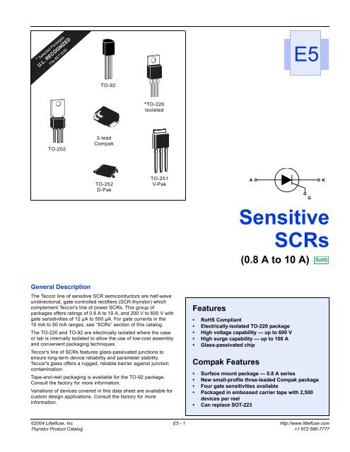
<strong>Sensitive</strong> <strong>SCRs</strong>Data SheetsIsolatedPart NumberNon-isolatedAAI T(1)V DRM &I DRM &V RRM I GT I RRM(2) (12) (20) (21)V TM(3) (10)ATYPEKGA6A8A10 AKATO-220GKAGTO-202K A GTO-251V-PakSee “Package Dimensions” section for variations. (11)TO-252D-PakI T(RMS) I T(AV)AmpsµAmpsVolts µAmps 25 °C 110 °C VoltsT C = T C =MAX MAX MIN MAX MAX MAX MAXS2006LS2 S2006FS21 S2006VS2 S2006DS2 6 3.8 200 200 5 250 1.6S4006LS2 S4006FS21 S4006VS2 S4006DS2 6 3.8 400 200 5 250 1.6S6006LS2 S6006FS21 S6006VS2 S6006DS2 6 3.8 600 200 5 250 1.6S2006LS3 S2006FS31 S2006VS3 S2006DS3 6 3.8 200 500 5 250 1.6S4006LS3 S4006FS31 S4006VS3 S4006DS3 6 3.8 400 500 5 250 1.6S6006LS3 S6006FS31 S6006VS3 S6006DS3 6 3.8 600 500 5 250 1.6S2008LS2 S2008FS21 S2008VS2 S2008DS2 8 5.1 200 200 5 250 1.6S4008LS2 S4008FS21 S4008VS2 S4008DS2 8 5.1 400 200 5 250 1.6S6008LS2 S6008FS21 S6008VS2 S6008DS2 8 5.1 600 200 5 250 1.6S2008LS3 S2008FS31 S2008VS3 S2008DS3 8 5.1 200 500 5 250 1.6S4008LS3 S4008FS31 S4008VS3 S4008DS3 8 5.1 400 500 5 250 1.6S6008LS3 S6008FS31 S6008VS3 S6008DS3 8 5.1 600 500 5 250 1.6S2010LS2 S2010FS21 S2010VS2 S2010DS2 10 6.4 200 200 5 250 1.6S4010LS2 S4010FS21 S4010VS2 S4010DS2 10 6.4 400 200 5 250 1.6S6010LS2 S6010FS21 S6010VS2 S6010DS2 10 6.4 600 200 5 250 1.6S2010LS3 S2010FS31 S2010VS3 S2010DS3 10 6.4 200 500 5 250 1.6S4010LS3 S4010FS31 S4010VS3 S4010DS3 10 6.4 400 500 5 250 1.6S6010LS3 S6010FS31 S6010VS3 S6010DS3 10 6.4 600 500 5 250 1.6Specific Test Conditionsdi/dt — Maximum rate-of-change of on-state current; I GT = 50 mA pulsewidth ≥15 µsec with ≤0.1 µs rise timedv/dt — Critical rate-of-rise of forward off-state voltageI 2 t — RMS surge (non-repetitive) on-state current for period of 8.3 msfor fusingI DRM and I RRM — Peak off-state current at V DRM and V RRMI GT — DC gate trigger current V D = 6 V dc; R L = 100 ΩI GM — Peak gate currentI H — DC holding current; initial on-state current = 20 mAI T — Maximum on-state currentI TSM — Peak one-cycle forward surge currentP G(AV) — Average gate power dissipationP GM — Peak gate power dissipationt gt — Gate controlled turn-on time gate pulse = 10 mA; minimumwidth = 15 µS with rise time ≤0.1 µst q — Circuit commutated turn-off timeV DRM and V RRM — Repetitive peak off-state forward and reverse voltageV GRM — Peak reverse gate voltageV GT — DC gate trigger voltage; V D = 6 V dc; R L = 100 ΩV TM — Peak on-state voltageGeneral Notes• Teccor 2N5064 and 2N6565 Series devices conform to all JEDECregistered data. See specifications table on pages <strong>E5</strong> - 2 and<strong>E5</strong> - 3.• The case lead temperature (T C or T L ) is measured as shown ondimensional outline drawings in the “Package Dimensions” sectionof this catalog.• All measurements (except I GT ) are made with an external resistorR GK = 1 kΩ unless otherwise noted.• All measurements are made at 60 Hz with a resistive load at anambient temperature of +25 °C unless otherwise specified.• Operating temperature (T J ) is -65 °C to +110 °C for EC Seriesdevices, -65 °C to +125 °C for 2N Series devices, -40 °C to+125 °C for “TCR” Series, and -40 °C to +110 °C for all others.• Storage temperature range (T S ) is -65 °C to +150 °C for TO-92devices, -40 °C to +150 °C for TO-202 and Compak devices, and-40 °C to +125 °C for all others.• Lead solder temperature is a maximum of +230 °C for 10 secondsmaximum ≥1/16" (1.59 mm) from case.http://www.littelfuse.com <strong>E5</strong> - 4 ©2004 Littelfuse, Inc.+1 972-580-7777 Thyristor Product Catalog
Data Sheets<strong>Sensitive</strong> <strong>SCRs</strong>V GT I H I GM V GRM P GM P G(AV) I TSM dv/dt di/dt t gt t q l 2 t(4) (12) (22)(5) (19) (17)(17)(6) (13)(8) (9)VoltsVolts/µSecT C = T C = T C =-40 °C 25 °C 110 °C mAmps Amps Volts Watts Watts Amps T C = 110 °C Amps/µSec µSec µSec Amps 2 SecMAX MAX MIN 60/50 Hz TYP TYP MAX1 0.8 0.25 6 1 6 1 0.1 100/83 10 100 4 50 411 0.8 0.25 6 1 6 1 0.1 100/83 8 100 4 50 411 0.8 0.25 6 1 6 1 0.1 100/83 8 100 4 50 411 0.8 0.25 8 1 6 1 0.1 100/83 10 100 5 45 411 0.8 0.25 8 1 6 1 0.1 100/83 8 100 5 45 411 0.8 0.25 8 1 6 1 0.1 100/83 8 100 5 45 411 0.8 0.25 6 1 6 1 0.1 100/83 10 100 4 50 411 0.8 0.25 6 1 6 1 0.1 100/83 8 100 4 50 411 0.8 0.25 6 1 6 1 0.1 100/83 8 100 4 50 411 0.8 0.25 8 1 6 1 0.1 100/83 10 100 5 45 411 0.8 0.25 8 1 6 1 0.1 100/83 8 100 5 45 411 0.8 0.25 8 1 6 1 0.1 100/83 8 100 5 45 411 0.8 0.25 6 1 6 1 0.1 100/83 10 100 4 50 411 0.8 0.25 6 1 6 1 0.1 100/83 8 100 4 50 411 0.8 0.25 6 1 6 1 0.1 100/83 8 100 4 50 411 0.8 0.25 8 1 6 1 0.1 100/83 10 100 5 45 411 0.8 0.25 8 1 6 1 0.1 100/83 8 100 5 45 411 0.8 0.25 8 1 6 1 0.1 100/83 8 100 5 45 41Electrical Specifications Notes(1) See Figure <strong>E5</strong>.1 through Figure <strong>E5</strong>.9 for current ratings atspecified operating temperatures.(2) See Figure <strong>E5</strong>.10 for I GT versus T C or T L .(3) See Figure <strong>E5</strong>.11 for instantaneous on-state current (i T ) versus onstatevoltage (v T ) TYP.(4) See Figure <strong>E5</strong>.12 for V GT versus T C or T L .(5) See Figure <strong>E5</strong>.13 for I H versus T C or T L .(6) For more than one full cycle, see Figure <strong>E5</strong>.14.(7) 0.8 A to 4 A devices also have a pulse peak forward current onstaterating (repetitive) of 75 A. This rating applies for operation at60 Hz, 75 °C maximum tab (or anode) lead temperature, switchingfrom 80 V peak, sinusoidal current pulse width of 10 µs minimum,15 µs maximum. See Figure <strong>E5</strong>.20 and Figure <strong>E5</strong>.21.(8) See Figure <strong>E5</strong>.15 for t gt versus I GT .(9) Test conditions as follows:– T C or T L ≤80 °C, rectangular current waveform– Rate-of-rise of current ≤10 A/µs– Rate-of-reversal of current ≤5 A/µs– I TM = 1 A (50 µs pulse), Repetition Rate = 60 pps– V RRM = Rated– V R = 15 V minimum, V DRM = Rated– Rate-of-rise reapplied forward blocking voltage = 5 V/µs– Gate Bias = 0 V, 100 Ω (during turn-off time interval)(10) Test condition is maximum rated RMS current except TO-92devices are 1.2 A PK ; T106/T107 devices are 4 A PK .(11) See package outlines for lead form configurations. When orderingspecial lead forming, add type number as suffix to part number.(12) V D = 6 V dc, R L = 100 Ω (See Figure <strong>E5</strong>.19 for simple test circuitfor measuring gate trigger voltage and gate trigger current.)(13) See Figure <strong>E5</strong>.1 through Figure <strong>E5</strong>.9 for maximum allowable casetemperature at maximum rated current.(14) I GT = 500 µA maximum at T C = -40 °C for T106 devices(15) I H = 10 mA maximum at T C = -65 °C for 2N5064 Series and2N6565 Series devices(16) I H = 6 mA maximum at T C = -40 °C for T106 devices(17) Pulse Width ≤10 µs(18) I GT = 350 µA maximum at T C = -65 °C for 2N5064 Series and2N6565 Series devices(19) Latching current can be higher than 20 mA for higher I GT types.Also, latching current can be much higher at -40 °C. See Figure<strong>E5</strong>.18.(20) T C or T L = T J for test conditions in off state(21) I DRM and I RRM = 50 µA for 2N5064 and 100 µA for 2N6565 at125 °C(22) TO-92 devices specified at -65 °C instead of -40 °C(23) T C = 110 °C©2004 Littelfuse, Inc. <strong>E5</strong> - 5 http://www.littelfuse.comThyristor Product Catalog +1 972-580-7777
<strong>Sensitive</strong> <strong>SCRs</strong>Data SheetsThermal Resistance (Steady State)R θJC [R θ JA ] °C/W (TYPICAL)Package Code E L F2 F C D VTypeTO-92 TO-220 TO-202Type 2, 4, & 41*Mounted on 1 cm 2 copper foil surface; two-ounce copper foilTO-202Type 1 & 3Compak0.8 A 75 [160] 60*1.5 A 50 [160]4.0 A 10 [100] 6.2 [80] 3.0 3.8 [85]6.0 A 4.0 [65] 4.3 1.8 2.48.0 A 3.4 3.9 1.5 2.110.0 A 3.0 3.4 1.45 1.72TO-252D-PakTO-251V-PakElectrical IsolationTeccor’s isolated sensitive <strong>SCRs</strong> will withstand a minimum highpotential test of 2500 V ac rms from leads to mounting tab overthe device's operating temperature range. The following tableshows other standard and optional isolation ratings.Electrical Isolation *from Leads to Mounting TabVACRMSTO-2202500 Standard4000 Optional ***UL Recognized File #E71639**For 4000 V isolation, use “V” suffix in part number.Maximum Allowable Case Temperature (T C ) – ˚C1301201101009080706050404 A TO-251and TO-252TCR22 DevicesCURRENT WAVEFORM: SinusoidalLOAD: Resistive or InductiveCONDUCTION ANGLE: 180˚CASE TEMPERATURE: Measuredas Shown on Dimensional DrawingT106 and T107Type 2 and 4T106 and T107Type 1 and 32.60 0.5 1.0 1.5 2.0 2.5 3.0 3.5 4.0RMS On-state Current [I T(RMS) ] – AmpsMaximum AllowableCase Temperature (T C) – ˚C13012011010090807060Figure <strong>E5</strong>.1EC SeriesCURRENT WAVEFORM: SinusoidalLOAD: Resistive or InductiveCONDUCTION ANGLE: 180˚CASE TEMPERATURE: Measuredas Shown on Dimensional DrawingCompakJEDEC 2N Series500.1 0.2 0.3 0.4 0.5 0.6 0.7 0.8 0.9 1.0RMS On-State Current [I T(RMS)] – AmpsMaximum Allowable Case Temperature versusRMS On-state CurrentFigure <strong>E5</strong>.2Maximum Allowable Case Temperature (T C ) – ˚CMaximum Allowable Case Temperature versusRMS On-state Current13012011010090807060EC SeriesCURRENT WAVEFORM: SinusoidalLOAD: Resistive or InductiveCONDUCTION ANGLE: 180˚CASE TEMPERATURE: Measuredas Shown on Dimensional DrawingCompakJEDEC 2N Series500.510 0.1 0.2 0.3 0.4 0.5 0.6Average On-state Current [I T(AV)] – AmpsFigure <strong>E5</strong>.3Maximum Allowable Case Temperature versusAverage On-state Currenthttp://www.littelfuse.com <strong>E5</strong> - 6 ©2004 Littelfuse, Inc.+1 972-580-7777 Thyristor Product Catalog
Data Sheets<strong>Sensitive</strong> <strong>SCRs</strong>Maximum AllowableCase Temperature (T C ) – ˚C1301201101009080706050TCR22DevicesCURRENT WAVEFORM: SinusoidalLOAD: Resistive or InductiveCONDUCTION ANGLE: 180˚CASE TEMPERATURE: Measuredas Shown on Dimensional DrawingT106 and T107Type 2 and 4T106 and T107Type 1 and 3400.95 1.65 1.9 2.540 0.5 1.0 1.5 2.0 2.5 3.0Average On-state Current [I T(AV) ] – AmpsMaximum AllowableAmbient Temperature (T A ) – ˚C14012010080604020T106/T107 TO-202Type 2 and 4and TO-251CURRENT WAVEFORM: SinusoidalLOAD: Resistive or InductiveCONDUCTION ANGLE: 180˚FREE AIR RATINGT106/T107 TO-202Type 1 and 3TO-2200 0.2 0.4 0.6 0.8 1.0 1.2 1.4Average On-state Current [I T(AV) ] – AmpsFigure <strong>E5</strong>.4Maximum Allowable Case Temperature versusAverage On-state CurrentFigure <strong>E5</strong>.7Maximum Allowable Ambient Temperature versusAverage On-state CurrentMaximum Allowable Ambient Temperature (T A ) – ˚CFigure <strong>E5</strong>.51401201008060401.5 A and JEDEC2N Series I T(AV)and EC Series I T(AV)CURRENT WAVEFORM: SinusoidalLOAD: Resistive or InductiveCONDUCTION ANGLE: 180˚FREE AIR RATINGEC Series I T(RMS)1.5 A Devicesand JEDEC2N Series I T(RMS)200 0.1 0.2 0.3 0.4 0.5 0.6 0.7 0.8 0.9On-state Current – AmpsMaximum Allowable Ambient Temperature versusOn-state CurrentMaximum AllowableCase Temperature (T C ) – ˚C11511010510095908580Figure <strong>E5</strong>.806 A TO-220and TO-2028 A TO-220and TO-20210 A TO-220and TO-2026 A TO-251and TO-252CURRENT WAVEFORM: SinusoidalLOAD: Resistive or InductiveCONDUCTION ANGLE: 180˚TEMPERATURE: Measured asShown on Dimensional Drawings8 A TO-251and TO-2522 4 6 8 10RMS On-state Current [I T(RMS) ] – AmpsMaximum Allowable Case Temperature versusRMS On-state Current10 A TO-251and TO-252Maximum AllowableAmbient Temperature (T A ) – ˚C140120100806040T106/T107 TO-202Type 2 and 4and TO-251CURRENT WAVEFORM: SinusoidalLOAD: Resistive or InductiveCONDUCTION ANGLE: 180˚FREE AIR RATINGT106/T107 TO-202Type 1 and 3TO-220Maximum AllowableCase Temperature (T C ) – ˚C1101051009590856 A TO-220and TO-2028 A TO-220and TO-20210 A TO-220and TO-2026 A TO-251and TO-252CURRENT WAVEFORM: SinusoidalLOAD: Resistive or InductiveCONDUCTION ANGLE: 180˚CASE TEMPERATURE: Measuredas Shown on Dimensional Drawings8 A TO-251and TO-25210 A TO-251and TO-252200 0.2 0.4 0.6 0.8 1.0 1.2 1.4 1.6 1.82.08001 2 3 4 5 67RMS On-state Current [I T(RMS) ] – AmpsAverage On-state Current [I T(AV) ] – AmpsFigure <strong>E5</strong>.6Maximum Allowable Ambient Temperature versusRMS On-state CurrentFigure <strong>E5</strong>.9Maximum Allowable Case Temperature versusAverage On-state Current©2004 Littelfuse, Inc. <strong>E5</strong> - 7 http://www.littelfuse.comThyristor Product Catalog +1 972-580-7777
<strong>Sensitive</strong> <strong>SCRs</strong>Data SheetsI GTI GT (TC = 25 ˚C)9.08.07.06.05.04.0See General Notes for specific deviceoperating temperature range.I HI H (T C = 25 ˚C)4.03.02.0See General Notes for specificoperating temperature range.Ratio of3.02.0Ratio of1.01.00-65 -40 -15 +25 +65 +110 +125Case Temperature (T C ) – ˚C0-65 -40 -15 +25 +65 +110 +125Case Temperature (T C ) – ˚CFigure <strong>E5</strong>.10 Normalized DC Gate-Trigger Current versusCase TemperatureFigure <strong>E5</strong>.13 Normalized DC Holding Current versus Case TemperatureInstantaneous On-state Current (i T ) – Amps322824201612840T C = 25˚C6 A to 10 A Devices4 A TO-251 and TO-2520.8 A to 1.5 A TO-92,T106/T107, andCompak0 .6 .8 1.0 1.2 1.4 1.6Instantaneous On-state Voltage (v T ) – VoltsFigure <strong>E5</strong>.11 Instantaneous On-state Current versusOn-state Voltage (Typical)2.0See General Notes for specificoperating temperature rangeV GTV GT (T C = 25 ˚C)1.51.0Ratio of0.50-65 -40 -15 +25 +65 +110 +125Case Temperature (T C ) – ˚CFigure <strong>E5</strong>.12 Normalized DC Gate-Trigger Voltage versusCase Temperaturehttp://www.littelfuse.com <strong>E5</strong> - 8 ©2004 Littelfuse, Inc.+1 972-580-7777 Thyristor Product Catalog
Data Sheets<strong>Sensitive</strong> <strong>SCRs</strong>Peak Surge (Non-repetitive)On-state Current (I TSM ) – Amps20010080605040302010865432110 A Devices4 A TO-251 and TO-252Notes:1) Gate control may be lost duringand immediately following surgecurrent interval.2) Overload may not be repeateduntil junction temperature hasreturned to steady-state rated value.SUPPLY FREQUENCY: 60 Hz SinusoidalLOAD: ResistiveRMS ON-STATE CURRENT: [I T(RMS) ]: MaxRated Value at Specified Case Temperature8 A DevicesTO-106and TO-1070.8 A TO-92and Compak1 2 3 4 5 6 8 10 20 30 40 50 60 80 100 200 300 400 600 1000Surge Current Duration – Full Cycles6 A Devices1.5 A DevicesFigure <strong>E5</strong>.14 Peak Surge On-state Current versus Surge Current DurationTurn-on Time (tgt) – µs100101.0I GT = 50 µA MAXI GT = 200 µA MAXI GT = 500 µA MAXI GT = 12 µA MAXT C = 25 ˚CAverage On-state Power Dissipation [P D(AV) ] – Watts5.04.03.02.01.0CURRENT WAVEFORM: Half Sine WaveLOAD: Resistive or InductiveCONDUCTION ANGLE: 180˚T106 and T1074 A TO-251 and TO-2520.8 A TO-92 and Compak1.5 A Devices0 1 2 3 4RMS On-state Current [I T(RMS) ] – AmpsFigure <strong>E5</strong>.16 Power Dissipation (Typical) versus RMS On-state Current0.10.01 0.1 1 10 100DC Gate Trigger Current (I GT ) – mAFigure <strong>E5</strong>.15 Typical Turn-on Time versus Gate Trigger Current©2004 Littelfuse, Inc. <strong>E5</strong> - 9 http://www.littelfuse.comThyristor Product Catalog +1 972-580-7777
<strong>Sensitive</strong> <strong>SCRs</strong>Data Sheets12Average On-statePower Dissipation [P D(AV) ] – Watts108642CURRENT WAVEFORM: Half Sine WaveLOAD: Resistive or InductiveCONDUCTION ANGLE: 180˚6 A to 10 ATO-220, TO-202,TO-251, and TO-252+6 V DC–ResetNormally-closedPushbuttonV1D.U.T.1001 k(1%)I GTIN4001I GV GT100R100 2 4 6 8 10RMS On-state Current [I T(RMS) ] – AmpsFigure <strong>E5</strong>.17 Power Dissipation (Typical) versus RMS On-state CurrentI LI L (T C = 25 ˚C)Ratio of9.08.07.06.05.04.03.02.01.0See General Notes for specific deviceoperating temperature range.0-65 -40 -15 +25 +65 +110 +125Case Temperature (T C ) – ˚CFigure <strong>E5</strong>.18 Normalized DC Latching Current versus Case TemperatureFigure <strong>E5</strong>.19 Simple Test Circuit for Gate Trigger Voltage andCurrent MeasurementNote: V1 — 0 V to 10 V dc meterV GT — 0 V to 1 V dc meterI G — 0 mA to 1 mA dc milliammeterR1 — 1 k potentiometerTo measure gate trigger voltage and current, raise gate voltage(V GT ) until meter reading V1 drops from 6 V to 1 V. Gate triggervoltage is the reading on V GT just prior to V1 dropping. Gate triggercurrent I GT can be computed from the relationshipVI GT= I GTG– ------------ Amps1000where I G is reading (in amperes) on meter just prior to V1 dropping.Note: I GT may turn out to be a negative quantity (trigger currentflows out from gate lead). If negative current occurs, I GT value isnot a valid reading. Remove 1 k resistor and use I G as the morecorrect I GT value. This will occur on 12 µA gate products.http://www.littelfuse.com <strong>E5</strong> - 10 ©2004 Littelfuse, Inc.+1 972-580-7777 Thyristor Product Catalog
Data Sheets<strong>Sensitive</strong> <strong>SCRs</strong>180160Peak Discharge Current (I TM ) – Amps14012010080604020I TMt Wt W= 5 TIME CONSTANTS0.8 A to 4 A1 Hz12 Hz60 Hz01.0 3.0 5.0 7.0 10 30 50 70 100Peak Current Duration (t W ) – µsFigure <strong>E5</strong>.20 Peak Repetitive Capacitor Discharge Current180160Peak Discharge Current (I TM ) – Amps140120100806040201 Hz12 HzI TM 60 Hzt W 0.8 A to 4 A01.0 3.0 5.0 7.0 10 30 50 70 100Peak Current Duration (t W ) – µsFigure <strong>E5</strong>.21 Peak Repetitive Sinusoidal Curve©2004 Littelfuse, Inc. <strong>E5</strong> - 11 http://www.littelfuse.comThyristor Product Catalog +1 972-580-7777
Notes