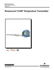
<strong>IF302</strong> – Operation and Maintenance Instruction <strong>Manual</strong>MAIN CIRCUIT BOARDINPUT CIRCUIT BOARDPOWERISOLATIONPOWERSUPPLYSIGNALSHAPINGSUPPLYFIRMWAREDOWLOADINTERFACEFLASHRAMMODEMDISPLAY BOARDLOCAL ADJUSTCPUEEPROMSIGNALISOLATIONA/DMUX(*) Resistor Shunt3 x 1001234DISPLAYCONTROLLERFigure 2.1 - <strong>IF302</strong> Block Diagram* WARNINGApply in the inputs of the conversor only current levels. Don't apply tension levels, because the shuntresistors are of 100R 1W and tension above 10 Vdc it can damage them.2.2
Section 3CONFIGURATIONOne of the many advantages of Fieldbus is that device configuration is independent of theconfigurator. The <strong>IF302</strong> may be configured by a third party terminal or operator console.The <strong>IF302</strong> contains three input transducer blocks, one resource block, one display transducer blockand function blocks.Function Blocks are not covered in this manual. For explanation and details of function blocks, seethe “Function Blocks <strong>Manual</strong>”.Transducer BlockHow to Configure a Transducer BlockTerminal NumberTransducer block insulates function block from the specific I/O hardware, such as sensors andactuators. Transducer block controls access to I/O through manufacturer specific implementation.This permits the transducer block to execute as frequently as necessary to obtain good data fromsensors without burdening the function blocks that use the data. It also insulates the function blocksfrom the manufacturer specific characteristics of certain hardware.By accessing the hardware, the transducer block can get data from I/O or passing control data to it.The connection between Transducer block and Input/Output Function blocks is called channel.Normally, transducer blocks perform functions, such as linearization, characterization, temperaturecompensation, control and exchange data to/from hardware.The transducer block has an algorithm, a set of contained parameters and a channel connecting it toa function block.The algorithm describes the behavior of the transducer as a data transfer function between the I/Ohardware and other function block. The set of contained parameters, it means, you are not able tolink them to other blocks, defines the user interface to the transducer block. They can be divided intoStandard and Manufacturer Specific.The standard parameters will be present for such class of device, as pressure, temperature,actuator, etc., whatever is the manufacturer. Oppositely, the manufacturers specific ones aredefined only by its manufacturer. As common manufacturer specific parameters, we have calibrationsettings, material information, linearization curve, etc.When you perform a standard routine as a calibration, you are conducted step by step by a method.The method is generally defined as guide line to help the user to make common tasks. TheSYSCON configurator identifies each method associated to the parameters and enables theinterface to it.The terminal number, which references a physical input, which is sent internally from the specifiedtransducer output to function block.It starts at one (1) for transducer number one until three (3) for transducer number three.The channel number of the AI block is related to the transducer’s terminal number. Channel number1, 2, 3 corresponds bi-univocally to the terminal block with the same number. Therefore, all the userhas to do is to select combinations: (1.1), (2.2), (3,3) for (CHANNEL, BLOCK).3.1


![[MI 019-120] I/A Series Mass Flowtubes Models CFS20 ... - Invensys](https://img.yumpu.com/48832334/1/190x245/mi-019-120-i-a-series-mass-flowtubes-models-cfs20-invensys.jpg?quality=85)