Guidelines for Best Practice and Quality Checking of Ortho Imagery
Guidelines for Best Practice and Quality Checking of Ortho Imagery
Guidelines for Best Practice and Quality Checking of Ortho Imagery
Create successful ePaper yourself
Turn your PDF publications into a flip-book with our unique Google optimized e-Paper software.
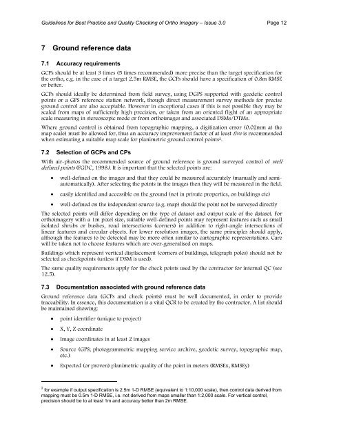
<strong>Guidelines</strong> <strong>for</strong> <strong>Best</strong> <strong>Practice</strong> <strong>and</strong> <strong>Quality</strong> <strong>Checking</strong> <strong>of</strong> <strong>Ortho</strong> <strong>Imagery</strong> – Issue 3.0 Page 127 Ground reference data7.1 Accuracy requirementsGCPs should be at least 3 times (5 times recommended) more precise than the target specification <strong>for</strong>the ortho, e.g. in the case <strong>of</strong> a target 2.5m RMSE, the GCPs should have a specification <strong>of</strong> 0.8m RMSEor better.GCPs should ideally be determined from field survey, using DGPS supported with geodetic controlpoints or a GPS reference station network, though direct measurement survey methods <strong>for</strong> preciseground control are also acceptable. However in exceptional cases if this is not possible they may bescaled from maps <strong>of</strong> sufficiently high precision, or taken from an oriented flight <strong>of</strong> an appropriatescale measuring in stereoscopic mode or from orthoimages <strong>and</strong> associated DSMs/DTMs.Where ground control is obtained from topographic mapping, a digitization error (0.02mm at themap scale) must be allowed <strong>for</strong>, thus an accuracy improvement factor <strong>of</strong> at least five is recommendedwhen estimating a suitable map scale <strong>for</strong> planimetric ground control points 2 .7.2 Selection <strong>of</strong> GCPs <strong>and</strong> CPsWith air-photos the recommended source <strong>of</strong> ground reference is ground surveyed control <strong>of</strong> welldefined points (FGDC, 1998). It is important that the selected points are:• well-defined on the images <strong>and</strong> that they could be measured accurately (manually <strong>and</strong> semiautomatically).After selecting the points in the images then they will be measured in the field.• easily identified <strong>and</strong> accessible on the ground (not in private properties, on buildings etc)• well-defined on the independent source (e.g. map) should the point not be surveyed directlyThe selected points will differ depending on the type <strong>of</strong> dataset <strong>and</strong> output scale <strong>of</strong> the dataset. Fororthoimagery with a 1m pixel size, suitable well-defined points may represent features such as smallisolated shrubs or bushes, road intersections (corners) in addition to right-angle intersections <strong>of</strong>linear features <strong>and</strong> circular objects. For lower resolution images, the same principles should apply,although the features to be detected may be more <strong>of</strong>ten similar to cartographic representations. Carewill be taken not to choose features which are over-generalised on maps.Buildings which represent vertical displacement (corners <strong>of</strong> buildings, telegraph poles) should not beselected as checkpoints (unless if DSM is used).The same quality requirements apply <strong>for</strong> the check points used by the contractor <strong>for</strong> internal QC (see12.5).7.3 Documentation associated with ground reference dataGround reference data (GCPs <strong>and</strong> check points) must be well documented, in order to providetraceability. In essence, this documentation is a vital QCR to be created by the contractor. A list shouldbe maintained showing:• point identifier (unique to project)• X, Y, Z coordinate• Image coordinates in at least 2 images• Source (GPS; photogrammetric mapping service archive, geodetic survey, topographic map,etc.)• Expected (or proven) planimetric quality <strong>of</strong> the point in meters (RMSEx, RMSEy)2 <strong>for</strong> example if output specification is 2.5m 1-D RMSE (equivalent to 1:10,000 scale), then control data derived frommapping must be 0.5m 1-D RMSE, i.e. not derived from maps smaller than 1:2,000 scale. For vertical control,precision should be to at least 1m <strong>and</strong> accuracy better than 2m RMSE.


