Guidelines for Best Practice and Quality Checking of Ortho Imagery
Guidelines for Best Practice and Quality Checking of Ortho Imagery
Guidelines for Best Practice and Quality Checking of Ortho Imagery

Create successful ePaper yourself
Turn your PDF publications into a flip-book with our unique Google optimized e-Paper software.
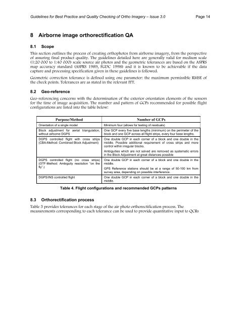
<strong>Guidelines</strong> <strong>for</strong> <strong>Best</strong> <strong>Practice</strong> <strong>and</strong> <strong>Quality</strong> <strong>Checking</strong> <strong>of</strong> <strong>Ortho</strong> <strong>Imagery</strong> – Issue 3.0 Page 148 Airborne image orthorectification QA8.1 ScopeThis section outlines the process <strong>of</strong> creating orthophotos from airborne imagery, from the perspective<strong>of</strong> assuring final product quality. The guidelines detailed here are generally valid <strong>for</strong> medium scale(1:20 000 to 1:40 000) scale source air photos <strong>and</strong> the geometric tolerances are based on the ASPRSmap accuracy st<strong>and</strong>ard (ASPRS 1989, FGDC 1998) <strong>and</strong> it is known to be achievable if the datacapture <strong>and</strong> processing specification given in these guidelines is followed.Geometric correction tolerance is defined using one parameter: the maximum permissible RMSE <strong>of</strong>the check points. Tolerances are as stated in the relevant ITT.8.2 Geo-referenceGeo-referencing concerns with the determination <strong>of</strong> the exterior orientation elements <strong>of</strong> the sensors<strong>for</strong> the time <strong>of</strong> image acquisition. The number <strong>and</strong> pattern <strong>of</strong> GCPs recommended <strong>for</strong> possible flightconfigurations are listed into the table below:Purpose/MethodOrientation <strong>of</strong> a single modelBlock adjustment <strong>for</strong> aerial triangulation,without airborne DGPSDGPS controlled flight with cross strips(CBA-Method: Combined Block Adjustment)DGPS controlled flight (no cross strips)(OTF-Method: Ambiguity resolution “on thefly”.)DGPS/INS controlled flightNumber <strong>of</strong> GCPsMinimum four (allows <strong>for</strong> testing <strong>of</strong> residuals)One GCP every five base lengths (minimum) on the perimeter <strong>of</strong> theblock <strong>and</strong> one GCP across all flight strips, every four base lengths.One double GCP in each corner <strong>of</strong> a block <strong>and</strong> one double in themiddle. Possible additional requirement <strong>of</strong> cross strips <strong>and</strong> morecontrol within irregular blocks.Ambiguities which are not solved are removed as systematic errorsin the Block Adjustment at great distances possibleOne double GCP in each corner <strong>of</strong> a block <strong>and</strong> one double in themiddle.GPS Reference stations should be at a range <strong>of</strong> 50-100 km fromsurvey area, depending on possible interference.One double GCP in each corner <strong>of</strong> a block <strong>and</strong> one double in themiddle.Table 4. Flight configurations <strong>and</strong> recommended GCPs patterns8.3 <strong>Ortho</strong>rectification processTable 5 provides tolerances <strong>for</strong> each stage <strong>of</strong> the air photo orthorectification process. Themeasurements corresponding to each tolerance can be used to provide quantitative input to QCRs