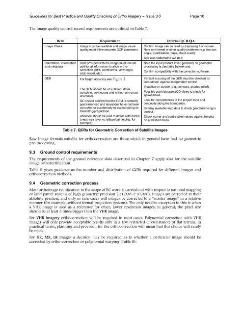
<strong>Guidelines</strong> <strong>for</strong> <strong>Best</strong> <strong>Practice</strong> <strong>and</strong> <strong>Quality</strong> <strong>Checking</strong> <strong>of</strong> <strong>Ortho</strong> <strong>Imagery</strong> – Issue 3.0 Page 18The image quality control record requirements are outlined in Table 7.Item Requirement Internal QCR/QAImage CheckImage must be readable <strong>and</strong> image visualquality must allow accurate GCP placement.Confirm image can be read by displaying it on-screen.Note any <strong>for</strong>mat or other quality problems (e.g. low sunangle, quantisation, haze, cloud cover).See also radiometric QA (6.3)Orientation in<strong>for</strong>mation<strong>and</strong> metadataData provided with the image must includeadditional in<strong>for</strong>mation to allow orthocorrection(RPC coefficients, view angle,orbit model, etc.).DEM For height accuracy see Figure 2The DEM should be <strong>of</strong> sufficient detail,complete, continuous <strong>and</strong> without any grossanomalies.QC should confirm that the DEM is correctlygeoreferenced <strong>and</strong> elevations have not beencorrupted or accidentally re-scaled during re<strong>for</strong>matting/preparation.Attention should be paid to datum references(mean sea level vs. ellipsoidal heights, <strong>for</strong>example)Table 7. QCRs <strong>for</strong> Geometric Correction <strong>of</strong> Satellite ImagesNote the input product level; generally no geometricprocessing is desirable be<strong>for</strong>eh<strong>and</strong>.Confirm compatibility with the correction s<strong>of</strong>tware.Vertical accuracy <strong>of</strong> the DEM must be checked bycomparison against independent controlVisualise on-screen (e.g. contours, shaded relief).Possibly use histograms/3D views to check <strong>for</strong>spikes/holes.Look <strong>for</strong> completeness in the project zone <strong>and</strong>continuity along tile boundaries.Overlay available map data to check georeferencing iscorrect.Check corner <strong>and</strong> centre pixel values against heightson published maps.Raw Image <strong>for</strong>mats suitable <strong>for</strong> orthocorrection are those which in general have had no geometricpre-processing.9.3 Ground control requirementsThe requirements <strong>of</strong> the ground reference data described in Chapter 7 apply also <strong>for</strong> the satelliteimage orthorectification.Table 9 gives guidance as the number <strong>and</strong> distribution <strong>of</strong> GCPs required <strong>for</strong> different images <strong>and</strong>orthocorrection methods.9.4 Geometric correction processMost orthoimage rectification in the scope <strong>of</strong> EC work is carried out with respect to national mappingor l<strong>and</strong> parcel systems <strong>of</strong> high geometric precision (1:1,000-1:10,000). Images are corrected to theirabsolute position, <strong>and</strong> only in rare cases will images be corrected to a “master image” in a relativemanner (<strong>for</strong> example, without <strong>for</strong>mal projection systems). The only notable exception to this is whena VHR image is used as a reference <strong>for</strong> other, lower resolution images; in general, the pixel sizeshould be at least 3 times bigger than the VHR image.For VHR imagery orthocorrection will be required in most cases. Polynomial correction with VHRimages will only provide acceptable results only in a few restricted circumstances <strong>of</strong> flat terrain. Inpractical terms, planning <strong>and</strong> provision <strong>for</strong> the orthocorrection will mean that this choice will rarelybe made.For HR, MR, LR images a decision may be required as to whether a particular image should becorrected by ortho-correction or polynomial warping (Table 8).
<strong>Guidelines</strong> <strong>for</strong> <strong>Best</strong> <strong>Practice</strong> <strong>and</strong> <strong>Quality</strong> <strong>Checking</strong> <strong>of</strong> <strong>Ortho</strong> <strong>Imagery</strong> – Issue 3.0 Page 19Image/TerrainHR: Terrain variation > 250m overwhole imageHR: View angle at centre <strong>of</strong> image >15° from nadirCorrection ProcedureGenerally orthocorrect(For large image area, piecewisewarping could be possible)Generally orthocorrect(For flat image area, warping couldbe possible)MR <strong>and</strong> LR images Polynomial warp generallyacceptable but terrain variation iscriticalTable 8. Geometric Correction Procedure choice <strong>for</strong> HR,MR <strong>and</strong> LR imagesGenerally, the number <strong>of</strong> GCPs required when using the recommended approach (using vendorsuppliedRPCs) is as few as 2-4 GCPs per image scene but it also depends on the length strip <strong>and</strong> thelinearity <strong>of</strong> a specific system (e.g. QB). The distribution <strong>of</strong> the GCPs is not usually critical (e.g. IK) butwell distributed preferred.In case <strong>of</strong> large <strong>of</strong>f-nadir angles <strong>and</strong> terrain variations, it is preferred to deliver separate RPC files <strong>for</strong>each st<strong>and</strong>ard image <strong>for</strong>ming the strip, which will represent more accurate the exterior orientation <strong>of</strong>the sensor at the time <strong>of</strong> acquisition <strong>of</strong> each scene.As an alternative to single scene processing, <strong>and</strong> if appropriate s<strong>of</strong>tware is available, multiple imagescenes – or a “block” <strong>of</strong> images – <strong>for</strong> the same zone can be processed together to calculate the best fit<strong>for</strong> all images. It is not recommended to use less than one GCP per single scene in the block.Table 9 provides a summary <strong>of</strong> this guidance <strong>and</strong> tolerance specification <strong>for</strong> each stage <strong>of</strong> the satelliteorthocorrection process. The measurements corresponding to each tolerance should be used toprovide quantitative input to QCRs.Stage Practical procedure Acceptable toleranceOrbit model No check required. Present in header in<strong>for</strong>mationGCP selection,HR,MR,LR (e.g.SPOT, IRS,L<strong>and</strong>sat)GCP selection, VHRwith vendor suppliedRPC processingGCP selection, VHRwith physical modelRPC generationfrom ground controlGCP Blunder CheckPolynomial warp(only)Rectification resultsGCPs should be well distributed (in grid) with points asnear as possible to each corner/edge (no extrapolation).Recommendation is to use supplied RPC data <strong>and</strong> 4GCPs located in the image corners.For strip scenes, additional control should be used (e.g.Ikonos, Quickbird).For VHR block processing (multiple scenes), groundcontrol may be reduced up to 1 GCP per scene ifsufficient good tie points available between imageryVHR orthorectification using a physical sensor modelusually requires more GCPs (than RCP), depending onthe specific sensor.This method should not to be used (non reliable <strong>and</strong>GCP intensive).Residuals should be calculated when redundancyavailable in GCPs; otherwise check independent points.Use a first or second order polynomial, third order mustnot be used.Calculate RMSE discrepancy on 10 independent checkpoints per image (if available) ORRecord the prediction sum <strong>of</strong> squares (PRESS) – ifavailable.Record the residuals <strong>and</strong> RMSE <strong>for</strong> each GCPcompared to the fitted model.Polynomial warp: > 15 GCPS per scene.Physical model orthorectification (at least 9GCPs per scene)Minimum, 2 - 4 per scene, additional GCPscould be needed due to strip length <strong>and</strong> thelinearity <strong>of</strong> the system (e.g. plus 2 peradditional 100km 2 <strong>of</strong> strip scene)Generally GCP distribution not critical, but welldistributed preferred.GCP preferably fall in overlap zones (imagecorners) but not criticalMore than 4 GCPs (depending on theunknowns).per scene.Distribution <strong>of</strong> GCPs should cover full AOI.Maximum residual should not exceed 3 x thetarget RMSE.Record the polynomial order in themetadata/QCR.Checkpoint RMSE < tolerance <strong>for</strong> geometricaccuracy.√PRESS < tolerance <strong>for</strong> geometric accuracy.RMSE if calculated on residuals should < 0.5 xtolerance <strong>for</strong> geometric accuracy: SaveGCPs/residuals to file