Image to Finite Element Mesh: An End to End Workflow - 3D Slicer
Image to Finite Element Mesh: An End to End Workflow - 3D Slicer
Image to Finite Element Mesh: An End to End Workflow - 3D Slicer

You also want an ePaper? Increase the reach of your titles
YUMPU automatically turns print PDFs into web optimized ePapers that Google loves.
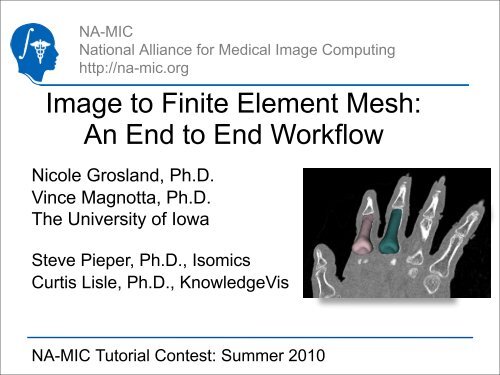
NA-MICNational Alliance for Medical <strong>Image</strong> Computinghttp://na-mic.org<strong>Image</strong> <strong>to</strong> <strong>Finite</strong> <strong>Element</strong> <strong>Mesh</strong>:<strong>An</strong> <strong>End</strong> <strong>to</strong> <strong>End</strong> <strong>Workflow</strong>Nicole Grosland, Ph.D.Vince Magnotta, Ph.D.The University of IowaSteve Pieper, Ph.D., IsomicsCurtis Lisle, Ph.D., KnowledgeVisnicole-grosland@uiowa.eduNA-MIC Tu<strong>to</strong>rial Contest: Summer 2010
Learning ObjectiveAfter following this tu<strong>to</strong>rial,you will be able <strong>to</strong> use<strong>Slicer</strong>3 <strong>to</strong> execute a fullworkflow from a sourceimage all the way throughthe creation andevaluation of an objectʼs<strong>3D</strong> volumetric finiteelement (FE) meshNational Alliance for Medical <strong>Image</strong> Computinghttp://na-mic.org © 2010, ARR
Pre-requisites• This tu<strong>to</strong>rial assumes the user is familiar with loadingimage datasets and creating basic label maps in <strong>Slicer</strong>.Please consult the following prerequisite material if youwant <strong>to</strong> brush up on these skills first:–Data Loading & Visualization tu<strong>to</strong>rial• Sonia Pujol, Ph.D., Harvard/SPL• http://www.slicer.org/slicerWiki/images/c/c9/<strong>3D</strong>DataLoading<strong>An</strong>dVisualization_<strong>Slicer</strong>3.6_SoniaPujol.pdf–User documentation for the <strong>Slicer</strong>3 Edi<strong>to</strong>r module• Steve Pieper, Ph.D, Harvard/SPL, Isomics• http://www.slicer.org/slicerWiki/index.php/Modules:Edi<strong>to</strong>r-Documentation-3.6National Alliance for Medical <strong>Image</strong> Computinghttp://na-mic.org © 2010, ARR
Pre-requisites• The user may use hand segmentation or anysegmentation algorithm <strong>to</strong> create surfaces for meshing.One of the simplest algorithms <strong>to</strong> use is <strong>Slicer</strong>3’s FastMarching Segmentation module:• Fast Marching Segmentation documentation–Adriy Fedorov, Ph.D., Harvard/SPL–http://www.slicer.org/slicerWiki/index.php/Modules:FastMarchingSegmentation-Documentation-3.6National Alliance for Medical <strong>Image</strong> Computinghttp://na-mic.org © 2010, ARR
Material• This tu<strong>to</strong>rial requires the installation of the<strong>Slicer</strong>3.6 release and the tu<strong>to</strong>rial dataset.They are available at the followinglocations:• <strong>Slicer</strong>3.6 downloadpage –http://www.slicer.org/pages/Downloads/• Tu<strong>to</strong>rial dataset:–http://www.slicer.org/slicerWiki/index.php/File:IAFE<strong>Mesh</strong>Data-Tu<strong>to</strong>rialContestSummer2010.zipDisclaimer: It is the responsibility of the user of <strong>Slicer</strong> <strong>to</strong> comply with both the termsof the license and with the applicable laws, regulations, andrules.National Alliance for Medical <strong>Image</strong> Computinghttp://na-mic.org © 2010, ARR
Material• A Users Guide is available for the IA-FE<strong>Mesh</strong> module,which covers the step by step process of meshcreation.• For additional assistance, consult the Users Guideavailable here–https://mri.radiology.uiowa.edu/downloads/IA-FE<strong>Mesh</strong>_Manual_version1.pdf6National Alliance for Medical <strong>Image</strong> Computinghttp://na-mic.org © 2010, ARR
Material• Interactive screencasts showing the following operationsare available from the NA-MIC wiki website:• Creating and importing a <strong>Slicer</strong> model–http://wiki.na-mic.org/Wiki/index.php/File:<strong>Mesh</strong>ing-1-labelmapmodel-import.mov• Simple Editing of Building Blocks around a surface–http://wiki.na-mic.org/Wiki/index.php/File:<strong>Mesh</strong>ing-2-buildingblocks.mov• Creating a mesh from a surface and building blocks–http://wiki.na-mic.org/Wiki/index.php/File:<strong>Mesh</strong>ing-3-meshcreation.mov• Evaluating and Improving <strong>Mesh</strong> Quality–http://wiki.na-mic.org/Wiki/index.php/File:<strong>Mesh</strong>ing-4-mesh-qualitytab.movNational Alliance for Medical <strong>Image</strong> Computinghttp://na-mic.org © 2010, ARR
Platform• The IA-FE<strong>Mesh</strong> <strong>Slicer</strong>3 Module wasdeveloped using both Linux (32 and 64 bit)and Mac (OS X 10.4 -10.6)• The module has been tested on both Linux64-bit and Mac (OS X10.6)National Alliance for Medical <strong>Image</strong> Computinghttp://na-mic.org © 2010, ARR
OverviewIn this tu<strong>to</strong>rial, we will…• Create a label map and a corresponding surface modelof a structure of interest from a source image• Import the surface model in<strong>to</strong> the IA-FE<strong>Mesh</strong> module• Interactively create a volumetric hexahedral mesh ofthe object of interest• Examine and improve the quality of the mesh• Export the mesh for continued processing in acommercial finite element solver (e.g. Abaqus)• Review the steps <strong>to</strong> create an object mesh fromimagery sourceNational Alliance for Medical <strong>Image</strong> Computinghttp://na-mic.org © 2010, ARR
Loading <strong>Image</strong> Data1. Select the <strong>Slicer</strong>3Volume Module2. Select the “VolumeFile” but<strong>to</strong>n <strong>to</strong> choosea file from thefilesystem. Manyimage formats aresupported.3. Hit “Apply” <strong>to</strong> read theimage in<strong>to</strong> the currentsessionNational Alliance for Medical <strong>Image</strong> Computinghttp://na-mic.org © 2010, ARR
Creating a Labelmap• A label map is a special type of volume whereeach voxel contains a code indicating theobject <strong>to</strong> which the voxel belongs• Label maps are loaded and saved like images,but handled differently by <strong>Slicer</strong> because oftheir purposes as indica<strong>to</strong>rs• At right, we see a label map indicating thepresence of the finger bone superimposed overcorresponding background voxels from a CTimage of the finger11National Alliance for Medical <strong>Image</strong> Computinghttp://na-mic.org © 2010, ARR
Creating a Labelmap• In <strong>Slicer</strong>3, a region of interest can be selected byhand or with an algorithm. The <strong>Slicer</strong>3 Edi<strong>to</strong>r moduleand the Fast Marching Segmentation module are twoof the easiest ways <strong>to</strong> create label maps• The Edi<strong>to</strong>r provides a palette of <strong>to</strong>ols <strong>to</strong> interactivelyselect regions of an image:–Level Tracing au<strong>to</strong>matically selectsnearby voxels similar <strong>to</strong> the selected point–The paintbrush is a way <strong>to</strong> clean up oradd missing voxels after Level Tracing12National Alliance for Medical <strong>Image</strong> Computinghttp://na-mic.org © 2010, ARR
Creating a Label map• Select the Level Tracing <strong>to</strong>ol, move it around on theimage, and click repeatedly <strong>to</strong> select the desired region• Repeat thevoxel selectionoperations foreach slicecontaining theobject <strong>to</strong> besegmented13National Alliance for Medical <strong>Image</strong> Computinghttp://na-mic.org © 2010, ARR
More about Segmentation• Clearing unwanted voxels can accomplished bypainting with the clear label color (label=0)• Step-by-step instructions for using the <strong>Slicer</strong>3Edi<strong>to</strong>r are available on the <strong>Slicer</strong> wiki site:–http://www.slicer.org/slicerWiki/index.php/Modules:Edi<strong>to</strong>r-Documentation-3.6• A screencast is available which demonstrateslabel maps and shows how models are created:–http://wiki.na-mic.org/Wiki/index.php/File:<strong>Mesh</strong>ing-1-labelmap-model-import.movNational Alliance for Medical <strong>Image</strong> Computinghttp://na-mic.org © 2010, ARR
Smoothing the Label• After editing is complete, smooth the labelmap <strong>to</strong> reduce jagged edges on the voxelcon<strong>to</strong>ur. Use the Label Map Smoothingmodule• A smooth labelboundary generatesthe best quality finalmesh15National Alliance for Medical <strong>Image</strong> Computinghttp://na-mic.org © 2010, ARR
Create a Boundary Surface• Once label mapediting is complete, aboundary detectionalgorithm is run <strong>to</strong>wrap a con<strong>to</strong>uraround the label map• Select theModelMaker module<strong>to</strong> create the surface16National Alliance for Medical <strong>Image</strong> Computinghttp://na-mic.org © 2010, ARR
Smooth Even More?• The Surface Toolboxcan smooth thepolygonal surface ofthe model further ifneeded• Remember, a smoothboundary makes forhigher quality boundaryelements in the volumemesh17National Alliance for Medical <strong>Image</strong> Computinghttp://na-mic.org © 2010, ARR
Loading a Surface• The IA-FE<strong>Mesh</strong> specific part of the workflowcan begin with a surface loaded from anexternal file OR• a <strong>Slicer</strong>3 Model is imported from the current<strong>Slicer</strong>3 sessionSTL, VTK, or VTP fileCurrent <strong>Slicer</strong>3 Session (MRML Scene)Import Model18National Alliance for Medical <strong>Image</strong> Computinghttp://na-mic.org © 2010, ARR
Importing a Surface Model• <strong>An</strong>y Model object in the current <strong>Slicer</strong> MRML scenecan be imported in<strong>to</strong> the meshing module <strong>to</strong> start ameshing workflow• Select the ImportModel selectionfrom the Surfacetab in IA-FE<strong>Mesh</strong>National Alliance for Medical <strong>Image</strong> Computinghttp://na-mic.org © 2010, ARR
Creating a Building Block• The surface is surrounded by Building Blocks<strong>to</strong> represent the shape <strong>to</strong> the meshingalgorithm• Building blocks are made through aninteractive widget editing process• Please refer <strong>to</strong> the screencast as an exampleof the steps:–http://wiki.na-mic.org/Wiki/index.php/File:<strong>Mesh</strong>ing-2-buildingblocks.movNational Alliance for Medical <strong>Image</strong> Computinghttp://na-mic.org © 2010, ARR
Creating a Building Block1. Select the Block(s) Tab2. Select Create from the drop down menu3. Check Create Block from Surface Bounds4. Click Apply2.1.4.Sample Generated Building Block3.National Alliance for Medical <strong>Image</strong> Computinghttp://na-mic.org © 2010, ARR
Manipulating the Building Block1. Select the Blocks tab2. Select Build/Edit from the drop down menu3. Select the from the building blocks <strong>to</strong>olbara) Allows manipulation of vertices, edges, and faces of building blocksb) Red spheres will appear at the vertices. The size of these spherescan be scaled1.3a.2.3b.National Alliance for Medical <strong>Image</strong> Computinghttp://na-mic.org © 2010, ARR
Creating a <strong>Mesh</strong>• The surface imported in<strong>to</strong> IA-FE<strong>Mesh</strong> alongwith the building block surrounding thesurface are used <strong>to</strong> create the mesh• <strong>Mesh</strong> elements are created by projecting thebounding box mesh seeds through thevolume• Please refer <strong>to</strong> the screencast as an exampleof the process:–http://wiki.na-mic.org/Wiki/index.php/File:<strong>Mesh</strong>ing-3-meshcreation.movNational Alliance for Medical <strong>Image</strong> Computinghttp://na-mic.org © 2010, ARR
Assigning <strong>Mesh</strong> Seeds1. Select the <strong>Mesh</strong> tab2. Select Assign/Edit <strong>Mesh</strong> Seeds from the drop down menu1.2.National Alliance for Medical <strong>Image</strong> Computinghttp://na-mic.org © 2010, ARR
Assigning <strong>Mesh</strong> Seeds (2)3. Select the but<strong>to</strong>n <strong>to</strong> visualize the distribution ofmesh seeds4. To change this assignment, select either <strong>Element</strong> Length orNumber of Divisions from the drop down menu.5. Click on a block with the left mouse but<strong>to</strong>n6. Enter the values of your choice7. Select Apply8. Select Cancel <strong>to</strong> exit the mesh seeds operation3.5.6.4.7. 8.National Alliance for Medical <strong>Image</strong> Computinghttp://na-mic.org © 2010, ARR
Creating a <strong>Mesh</strong>1. Select the <strong>Mesh</strong> tab2. Select Create from the drop downmenu3. Select Volumetric <strong>Mesh</strong>4. Select Building Block in the followingdrop down menu5. Provide starting node/elementnumbers and a descriptive label <strong>to</strong>be associated with the mesh definition6. Selection Elliptical in the Interpolationdrop down menu7. Uncheck Perform Smooth for theinitial attempt8. Select Apply <strong>to</strong> generate the mesh7.2.3.4.5.6.1.National Alliance for Medical <strong>Image</strong> Computinghttp://na-mic.org © 2010, ARR
Check <strong>Mesh</strong> Quality• Once mesh creation is complete, advance<strong>to</strong> the Quality tab on the interface <strong>to</strong> reviewthe quality according <strong>to</strong> several metrics• The process is demonstrated in thefollowing screencast–http://wiki.na-mic.org/Wiki/index.php/File:<strong>Mesh</strong>ing-4-mesh-quality-tab.movNational Alliance for Medical <strong>Image</strong> Computinghttp://na-mic.org © 2010, ARR
Checking <strong>Mesh</strong> Quality1. Select the Quality tab2. Select Evaluate/Display <strong>Mesh</strong> Quality from the drop down menu1.2.National Alliance for Medical <strong>Image</strong> Computinghttp://na-mic.org © 2010, ARR
Checking <strong>Mesh</strong> Quality (2)3. Select your Metric of Choice from the Metric drop down menu4. Click the but<strong>to</strong>n5. Close summary report window after viewing6. Click Cancel <strong>to</strong> exit the mesh quality check module3.4.National Alliance for Medical <strong>Image</strong> Computinghttp://na-mic.org © 2010, ARR
Check Interior <strong>Element</strong>s• Use the Cut Plane but<strong>to</strong>n <strong>to</strong> examineinterior elements by dragging the planeinteractivelyNational Alliance for Medical <strong>Image</strong> Computinghttp://na-mic.org © 2010, ARR
Improving <strong>Mesh</strong> Quality1. Select the Quality tab2. Select <strong>Mesh</strong> Improvement from the drop down menu3. Check <strong>to</strong> ensure that the surface, block, and mesh of interestpopulate the <strong>Mesh</strong> Component frame4. Select an interpolation method from the Interpolation dropdown menu5. Enter the desired number of smoothing iterations for theexternal nodes1.6. Click Apply2.3.6.4.5.National Alliance for Medical <strong>Image</strong> Computinghttp://na-mic.org © 2010, ARR
Improving <strong>Mesh</strong> Quality (2)7. Adjust the smoothing parameters by <strong>to</strong>ggling between theEvaluate/Display <strong>Mesh</strong> Quality and <strong>Mesh</strong> Improvemen<strong>to</strong>perations until the desired mesh is achievedNational Alliance for Medical <strong>Image</strong> Computinghttp://na-mic.org © 2010, ARR
After <strong>Mesh</strong> Generation• After mesh generation is complete, the usercan add material properties and loadingconditions <strong>to</strong> prepare for external finite elementsolver execution• The following slides cover these options. Foradditional detail, refer <strong>to</strong> the IA-FE<strong>Mesh</strong> UsersGuide–https://mri.radiology.uiowa.edu/downloads/IA-FE<strong>Mesh</strong>_Manual_version1.pdfNational Alliance for Medical <strong>Image</strong> Computinghttp://na-mic.org © 2010, ARR
Assigning Material Properties1. Select the Materials tab2. Select the User-Defined option from the main menu3. To add additional element sets, press• A number of options are available for selecting element setsNational Alliance for Medical <strong>Image</strong> Computinghttp://na-mic.org © 2010, ARR
Material Properties (2)<strong>Element</strong> Set Definition Examples• Cortical Bone Set Definition1. Select the surface element but<strong>to</strong>n: .2. Hold Ctrl but<strong>to</strong>n while using the left mouse but<strong>to</strong>n <strong>to</strong> drag a rubberband box around theelements of interest• Selected elements will be green3. To accept the chosen elements, click the right mouse but<strong>to</strong>n while hovering over the mesh• Accepted elements will turn red4. Opacity can be modified <strong>to</strong> better visualize the data5. Once the selection is finalized, enter a Set Label (e.g. cortical bone)6. Click <strong>to</strong> accept the selection• Cancellous Bone Definition1. Repeat the steps above except hit the but<strong>to</strong>n prior <strong>to</strong> accepting the element selection andassigning a new Set Label.2. Reduce the opacity <strong>to</strong> see the element set you have defined3. Click the but<strong>to</strong>n <strong>to</strong> close the Define <strong>Element</strong> Set window 1. 2.National Alliance for Medical <strong>Image</strong> Computinghttp://na-mic.org © 2010, ARR
Assigning Material Properties• Material Property Assignments1. Select an element set using the “<strong>Element</strong> Set” drop downmenu2. Enter the desired Modulus3. Enter the desired Poisson’s Ratio4. Click Apply5. Repeat this procedure for each material assignment6. Click Cancel <strong>to</strong> exit the operation1.2.3.4. 6.National Alliance for Medical <strong>Image</strong> Computinghttp://na-mic.org © 2010, ARR
Assigning Material Properties• Visualizing the Material Property Assignments1. Select the Materials tab2. Select Display Material Properties from the drop down menu3. Select the desired element set from the <strong>Element</strong> Set drop downmenu4. Use the but<strong>to</strong>n <strong>to</strong> display a cutting plane which may bemanipulated <strong>to</strong> view internal element definitions2.3.4.National Alliance for Medical <strong>Image</strong> Computinghttp://na-mic.org © 2010, ARR
Load and Boundary Conditions1. Select the Load/BC tab2. Select the STEP – Load/BC Assignments from the drop down menu3. Select4. Select from the Node Set <strong>to</strong>olbar• This enables the nodes associated with a face of a buildingblock <strong>to</strong> be readily chosen4.1.2.National Alliance for Medical <strong>Image</strong> Computinghttp://na-mic.org © 2010, ARR
Load and Boundary Conditions (2)5. Hold the Ctrl but<strong>to</strong>n and use the left mouse but<strong>to</strong>n <strong>to</strong> choose a nodeassociated with the building block face of interest• Nodes associated with selected face will be highlighted in green6. To accept the chosen nodes, click the right mouse but<strong>to</strong>n whilehovering over the mesh• All nodes associated with the chosen face will turn red• Opacity can be changed using the slider bar7. Once the selection is finalized, enter a Set Label8. Click9. Click6.7.8. 9.National Alliance for Medical <strong>Image</strong> Computinghttp://na-mic.org © 2010, ARR
Load and Boundary Conditions (3 )10.Provide a descriptive heading in the Step Subheadingtextbox11.Select desired Load/Displacement type in the drop downmenu12.Select the appropriate Node Set13.Assign x, y, and z directions11.12.13.National Alliance for Medical <strong>Image</strong> Computinghttp://na-mic.org © 2010, ARR
Load and Boundary Conditions (4)14. Select Apply <strong>to</strong> update the Load/BC assignments15. Visual confirmation will be provided on the mesh in theView Panel15.National Alliance for Medical <strong>Image</strong> Computinghttp://na-mic.org © 2010, ARR
1. Select the *STEP Definitionsbut<strong>to</strong>n• Please refer <strong>to</strong> theABAQUS manualregarding theseparameters2. Use the NSET and ELSETdrop down menus <strong>to</strong> selectthe sets of interest3. Click Apply in each submenu<strong>to</strong> commit your selectionIA-FE<strong>Mesh</strong> Tu<strong>to</strong>rial - MIMX Labora<strong>to</strong>ryNational Alliance for Medical <strong>Image</strong> Computing--
• Save the FE <strong>Mesh</strong>1. Select Save from the <strong>Mesh</strong> Tab• This can be performed at any step through themesh development process• Export the FE <strong>Mesh</strong> in ABAQUS file format1. Select Export ABAQUS file from the <strong>Mesh</strong> Tab• This can be performed at any step through themesh development processIA-FE<strong>Mesh</strong> Tu<strong>to</strong>rial - MIMX Labora<strong>to</strong>ryNational Alliance for Medical <strong>Image</strong> Computing--
Review of <strong>Workflow</strong> Steps• Input an image• Create, smooth, (andoptionally dilate) the labelmap• Use ModelMaker <strong>to</strong> create apolygonal surface model• Use Surface Tools <strong>to</strong> furthersmooth model polys usingLaplacian smoothing• Import the model in<strong>to</strong> IA-FE<strong>Mesh</strong> using Surface/ImportModel from the MRML scene• Create Building Blockssurrounding the surface• Assign mesh seeds andCreate the <strong>Mesh</strong>• View the mesh quality• Improve the mesh qualitythrough smoothing• Add Material Properties• Add Initial BoundaryConditions• Export <strong>to</strong> FE Solver(Abaqus)National Alliance for Medical <strong>Image</strong> Computinghttp://na-mic.org © 2010, ARR
Conclusion• It is now possible <strong>to</strong> perform end <strong>to</strong> endprocessing from source imagery all the waythrough <strong>Finite</strong> <strong>Element</strong> mesh generation, meshanalysis, and mesh optimization using <strong>Slicer</strong>3• Volumetric meshes for objects can be createdthrough a simple, intuitive process• <strong>An</strong>y <strong>Slicer</strong>3 model can be imported <strong>to</strong> start themesh generation processNational Alliance for Medical <strong>Image</strong> Computinghttp://na-mic.org © 2010, ARR
Acknowledgments• National Alliance for Medical <strong>Image</strong> ComputingNIH U54EB005149National Institute of Biomedical Imaging and BioengineeringR21EB001501 and R01EB005973Musculoskeletal Imaging Modeling and EXperimentation (MIMX)Labora<strong>to</strong>ryThe University of IowaNational Alliance for Medical <strong>Image</strong> Computinghttp://na-mic.org © 2010, ARR