- Page 2 and 3: Introductory RemarksAir vehicles ar
- Page 4 and 5: Aircraft Performance Basics(Interna
- Page 6 and 7: Basic Relationships to Uderstand th
- Page 8 and 9: Atmosphere with Constant Temperatur
- Page 10 and 11: Atmosphere with Linear Temperature
- Page 12 and 13: Atmosphere with Linear Temperature
- Page 14 and 15: International Standard AtmosphereCh
- Page 16 and 17: Important Aircraft Speed Terms to K
- Page 18 and 19: Air Compressibility EffectsA mathem
- Page 20 and 21: Example ComputationBoeing 737-300 (
- Page 22 and 23: Sample Matlab Code Used (ISAM.m)Vir
- Page 24 and 25: Plot of CAS vs. TAS (Subsonic Aircr
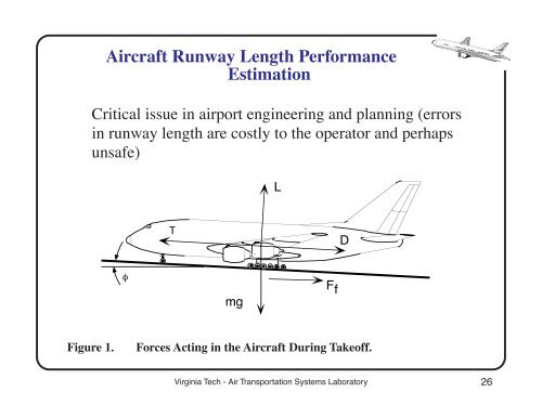
- Page 28 and 29: Functional Forms of the ForcesThe f
- Page 30 and 31: Notes on Various Parameters1) C L a
- Page 32 and 33: Remarks About the Aircraft Accelera
- Page 34 and 35: Flap Angle• Angle formed between
- Page 36 and 37: Remarks• The mass of the aircraft
- Page 38 and 39: • At large flap angles (> 25 degr
- Page 40 and 41: A Word on Stalling and Lift-off Spe
- Page 42 and 43: These considerations are necessary
- Page 44 and 45: Integration of Acceleration Equatio
- Page 46 and 47: Aircraft Speed During Takeoff RollN
- Page 48 and 49: Takeoff Roll Distance vs. Aircraft
- Page 50 and 51: General Procedure for Runway Length
- Page 52 and 53: FAR Certification ProceduresFAR 25
- Page 54 and 55: Landing Distance CaseThe landing di
- Page 56 and 57: Engine-Out Takeoff CaseDictated by
- Page 58 and 59: Runway Length Procedures (AC 150/53
- Page 60 and 61: Contents of Advisory Circular 150/5
- Page 62 and 63: Groupings Method AC 150/5325-4 (Fig
- Page 64 and 65: Sample Calculations (FAA AC 150-532
- Page 66 and 67: a) If MALW > DTW use DTW in your co
- Page 68 and 69: III) Landing and Takeoff Runway Len
- Page 70 and 71: I) Landing Analysisa) Estimate the
- Page 72 and 73: Simple interpolation for a flap ang
- Page 74 and 75: c) Compute the takeoff runway lengt
- Page 76 and 77:
Runway Length Analysis usingAircraf
- Page 78 and 79:
IAD-BGR TripIAD4,200 nmBGRVirginia
- Page 80 and 81:
Boeing 777-200 (GE Engines)Virginia
- Page 82 and 83:
Computation of Fuel WeightThis anal
- Page 84 and 85:
Explanation of Payload-Range Diagra
- Page 86 and 87:
Payload-Range Diagrams Explanations
- Page 88 and 89:
Sample Payload Range DiagramsPayloa
- Page 90 and 91:
Payload Range Diagrams (B777)Virgin
- Page 92 and 93:
Payload Range Diagrams (A320)Virgin
- Page 94 and 95:
Payload Range Dagrams (A380)Virgini
- Page 96 and 97:
Presentation of Runway Length Infor
- Page 98 and 99:
Boeing 777-200 HGW Takeoff Performa
- Page 100 and 101:
Landing AnalysisThis analysis is si
- Page 102 and 103:
Reconcile Takeoff and Landing Cases
- Page 104 and 105:
Other Considerations in Runway Leng
- Page 106 and 107:
Some Runway Design TermsThe followi
- Page 108 and 109:
Sketch of RPZVirginia Tech - Air Tr
- Page 110 and 111:
Runway Object Free Area (ROFA or OF
- Page 112 and 113:
OFA Dimensions (Approach Cat. C and
- Page 114 and 115:
Example Runway Design for Boeing 77
- Page 116 and 117:
Climb PerformanceMany airport and a
- Page 118 and 119:
Climb Performance Model Simplificat
- Page 120 and 121:
Final Derivation of Climb Rate Expr
- Page 122 and 123:
Modeling Aircraft Thrust• Thrust
- Page 124 and 125:
Sample Thrust Variations (PW JT9D E
- Page 126 and 127:
Takeoff Thrust Variations with Spee
- Page 128 and 129:
Variations of Cruise TSFC (PW JT9D
- Page 130:
Typical Rate of Climb EnvelopeItera