Manuale Officina LGW 523-627 - lombardini service
Manuale Officina LGW 523-627 - lombardini service
Manuale Officina LGW 523-627 - lombardini service

Create successful ePaper yourself
Turn your PDF publications into a flip-book with our unique Google optimized e-Paper software.
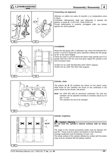
Disassembly / Reassembly4Connecting rod alignmentUtilizzare un calibro con piano di riscontro o un comparatore comein figura.Controllare l'allineamento degli assi utilizzando lo spinotto delpistone; lo scarto A = 0,015 mm;. limite 0,030 mm.Piccole deformazioni si possono correggere sotto una pressaagendo con sforzi graduali.120 121CYLINDERSReset the dial gauge with a calibrated ring: check the diameter D inpoints 1, 2 and 3; repeat the same operation rotating the dial gaugeby 90° at the same heights.Check any wear in zone X where the piston rings operate and if it isgreater than the 0.05 mm max limit given adjust the cylinder to thenext increased value.72,000 mm for LDW 502-602-903-1204-1204/T engines;75,000 mm for LDW 702-1003-1404 engines.122123Cylinder, classThe pistons (A, B, C) locations are shown on the piston crownwhile those for the cylinders are found on the crankcase in thepoints shown by the arrows, see picture.Note: For LDW 502 with an aluminium crankcase, the cast ironcylinders can be adjusted normally to increase values by 0.5and 1.0 mm.The cylinders are not to be changed.124Cylinder roughnessCaution – WarningDo not treat the cylinder’s internal surfaces with an emerycloth.The angle of the crossed processing marks must be between 45°and 55°. These must be uniform and distinct in both directions.Average roughness must be between 0.5 and 1 µm.The whole surface of the cylinder affected by contact with the pistonrings must be rendered with the plateau method.125FOCS Workshop Manual_cod. 1.5302.351_7° ed_ rev. 06- 59 -