Manuale Officina LGW 523-627 - lombardini service
Manuale Officina LGW 523-627 - lombardini service
Manuale Officina LGW 523-627 - lombardini service

Create successful ePaper yourself
Turn your PDF publications into a flip-book with our unique Google optimized e-Paper software.
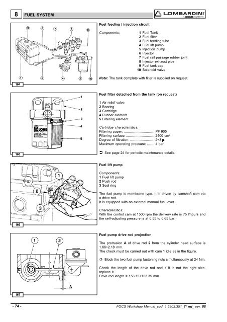
8FUEL SYSTEMFuel feeding / injection circuitComponents: 1 Fuel Tank2 Fuel filter3 Fuel feeding tube4 Fuel lift pump5 lnjection pump6 Injector7 Fuel rail passage rubber joint8 Injector exhaust pipe9 Fuel tank cap10 Solenoid valveNote: The tank complete with filter is supplied on request.164Fuel filter detached from the tank (on request)1 Air relief valve2 Bearing3 Cartridge4 Rubber element5 Filtering elementCartridge characteristics:Filtering paper: ................................ PF 905Filtering surface: .............................. 2400 cm 2Degree of filtration: .......................... 2÷3 µMaximum operating pressure: ........ 4 bar165 See page 24 for periodic maintenance details.Fuel lift pumpComponents:1 Fuel lift pump2 Push rod3 Seal ringThe fuel pump is membrane type. It is driven by camshaft cam viaa drive rod.It is equipped with an external manual fuel lever.Characteristics:With the control cam at 1500 rpm the delivery rate is 75 l/hours andthe self-adjusting pressure is at 0.55 to 0.65 bar.166Fuel pump drive rod projectionThe protrusion A of drive rod 2 from the cylinder head surface is1.66÷2.18 mm.The check must be carried out with cam 1 idle as in the figure. Block the two fuel pump fastening nuts simultaneously at 24 Nm.Check the length of the drive rod and if it is not the right size,replace it.Drive rod length = 153.15÷153.35 mm.167- 74 - FOCS Workshop Manual_cod. 1.5302.351_7° ed_ rev. 06