Manuale Officina LGW 523-627 - lombardini service
Manuale Officina LGW 523-627 - lombardini service
Manuale Officina LGW 523-627 - lombardini service

You also want an ePaper? Increase the reach of your titles
YUMPU automatically turns print PDFs into web optimized ePapers that Google loves.
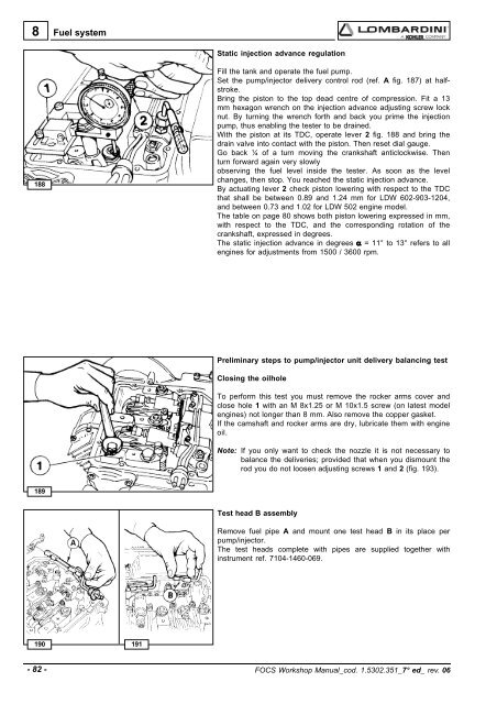
8Fuel systemStatic injection advance regulation188Fill the tank and operate the fuel pump.Set the pump/injector delivery control rod (ref. A fig. 187) at halfstroke.Bring the piston to the top dead centre of compression. Fit a 13mm hexagon wrench on the injection advance adjusting screw locknut. By turning the wrench forth and back you prime the injectionpump, thus enabling the tester to be drained.With the piston at its TDC, operate lever 2 fig. 188 and bring thedrain valve into contact with the piston. Then reset dial gauge.Go back ¼ of a turn moving the crankshaft anticlockwise. Thenturn forward again very slowlyobserving the fuel level inside the tester. As soon as the levelchanges, then stop. You reached the static injection advance.By actuating lever 2 check piston lowering with respect to the TDCthat shall be between 0.89 and 1.24 mm for LDW 602-903-1204,and between 0.73 and 1.02 for LDW 502 engine model.The table on page 80 shows both piston lowering expressed in mm,with respect to the TDC, and the corresponding rotation of thecrankshaft, expressed in degrees.The static injection advance in degrees α = 11° to 13° refers to allengines for adjustments from 1500 / 3600 rpm.Preliminary steps to pump/injector unit delivery balancing testClosing the oilholeTo perform this test you must remove the rocker arms cover andclose hole 1 with an M 8x1.25 or M 10x1.5 screw (on latest modelengines) not longer than 8 mm. Also remove the copper gasket.If the camshaft and rocker arms are dry, lubricate them with engineoil.Note: If you only want to check the nozzle it is not necessary tobalance the deliveries; provided that when you dismount therod you do not loosen adjusting screws 1 and 2 (fig. 193).189Test head B assemblyRemove fuel pipe A and mount one test head B in its place perpump/injector.The test heads complete with pipes are supplied together withinstrument ref. 7104-1460-069.190 191- 82 - FOCS Workshop Manual_cod. 1.5302.351_7° ed_ rev. 06