C.260 C.1100 1 050
C.260 C.1100 1 050
C.260 C.1100 1 050

Create successful ePaper yourself
Turn your PDF publications into a flip-book with our unique Google optimized e-Paper software.
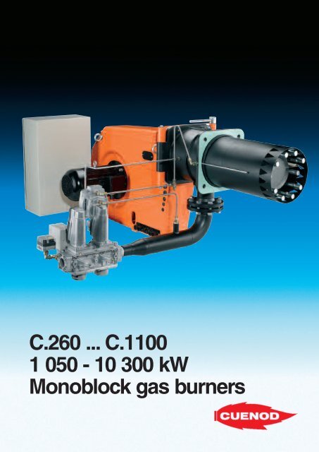
How the “Diamond Head” operates“Diamond Head”:clean gas combustion.CUENOD’s vast experience in the fieldof combustion combined with amethodical search for the bestprocesses has produced a highlyefficient range of burners.Low NOx gas combustion involvesinternal recirculation of the combustiongases. These gases are partially drawninto the base of the flame viatriangular-shaped openings at the tip ofthe combustion head.The gas injectors are placed in suchway that a large quantity of combustiongas is drawn in and rapidly mixed withthe air and the gas at the root of theflame. This mix crosses the mainreaction area and slows down thecombustion, thus reducing thetemperature.The advantage of this technique is thatit automatically adjusts the amount ofrecirculated combustion gas: the flamealways has the most reliable volumewhich has little affect on the nominaloutput of the generator, unlike externalrecirculation systems.Burners <strong>C.260</strong> to <strong>C.1100</strong> are equippedwith “Diamond” low NOx class IIIcombustion heads, guaranteeingemission values compliant withEuropean Standard EN 676.An O2 regulation system (optional) canbe used to control excess air.This staged combustion system(IME ® system) leads to a significantdecrease in thermal nitrogen oxide.
RTC ® systemThe combination of a functionalhousing design and advancedcombustion head technology ensures:- total access, essential for quick andeasy maintenance- complete disassembly of allcombustion head components(short and long) in a single actionmaintains initial combustion settingsduring maintenance procedures- compact and few mechanicalcomponents ensure quick and easycleanup- saves time since few tools arerequired.Noise levels ofmonoblock burners<strong>C.260</strong> to <strong>C.1100</strong>.Acoustic tests on the fans of <strong>C.260</strong> to<strong>C.1100</strong> CUENOD burners measuredthat noise levels for these burners arevery low for this power range.The configuration of certain systems,the proximity to sensitive areas and, inindustrial installations, the continuouspresence of personnel require specialsolutions to reduce noise. CUENODoffers a solution tailored to eachindividual situation or budget.The first solution involves the use of asound-proofing box.This box absorbs the noise producedby the burner, such as the sounds ofair being sucked in or blown out aswell as the noise made by the fanmotor. We offer two types of boxesdepending on the level of noisereduction required- CI.20 for a decrease of between15 and 20 dB(A), and,- CI.30 for a decrease of between20 and 30 dB(A).These cube-shaped devices completelyenclose the burner, leaving openingsfor the supply of fuel, electricity andcombustion air.They are mounted on wheels so theycan easily be moved when you needto work on the burner.The second solution recently madeavailable involves the use of theVariatron ® . This device is a frequencyregulator that adjusts the fan’s speedto the burner load. At low speeds, thefan speed and the air shutter positionare such that noise reduction canreach 15 to 20 dB(A).Adjusting the speed of the motor willadapt the air flow and the air pressureto the required amount: the Variatron ®limits amount of electrical energyconsumed for optimum efficiency.The Variatron ® is environment-friendlysince it adjusts the fan motor’soutput to the requirements of theburner/boiler.Ignition is inaudible and the burneroperates smoothly.Variatrons ® are sold as optionalfeatures and adapt quite well, withno modification required, to <strong>C.260</strong>to <strong>C.1100</strong> burners.Electrical powerabsorbed in %10<strong>050</strong>120 50 100Air flow in %Change in motor power outputwithout (1) and with Variatron ® (2)
Performance charts.Established chart at an altitude of 171 m and 20°CdaPa220180140<strong>C.260</strong>C.300 C.400 C.500C.620 C.750C.900 <strong>C.1100</strong>Packing.The burner is delivered attached to apalette and is protected by aheat-shrunk film.The combustion head is mounted ontothe body of the burner and a bag isincluded containing the screws forfixing it to the boiler.The gas manifold is attached to thepalette next to the burner body.The gas filter is not assembled.Operating instructions and the wiringdiagrams are also provided.10060Weight (without gas manifold)200Technical characteristics.Type1000 5000 10000kWECCertificateBurneroutputBoileroutput3 x 400 VMotoroutputFusesizekW kW kW A<strong>C.260</strong> 1060 - 2280 975 - 2100 4,0 16Burner<strong>C.260</strong>C.300C.400C.500C.620C.750C.900Weight in kg140140230240300330410C.300 1400 - 2800 1290 - 2575 4,0 16C.400 2000 - 3490 1840 - 3210 5,5 16C.500 2430 - 4400 2235 - 4<strong>050</strong> 7,5 20C.620 2800 - 5330 2575 - 4900 11,0 25C.750 3130 - 6540 2880 - 6015 15,0 40C.900 4600 - 7650 4230 - 7040 18,5 40<strong>C.1100</strong> 5920 - 10275 5445 - 9450 22,0 50Electrical connection.<strong>C.1100</strong> 450Power output control.Thermal output changes progressivelybetween two flows, after firing (flow atstart-up approx. 15% of nominal flow).Due to the significant power outputinvolved, an electronic power regulatoris either already incorporated(<strong>C.260</strong> to <strong>C.1100</strong> GD907), or can bemounted in the burner electrical box.Electrical installations must be carriedout in compliance with standards ineffect and local requirements.In particular: attention must be paid tothe burner supply main disconnectswitch which must be able to carry thetotal circuit output and isolate thecircuits.The following table provides motorpower outputs and corresponding fusesizes. Use “aM” fuses.The control circuit should be protectedby a 10 ampere fuse.For safety purposes, an isolatingtransformer and a 30mA differentialcircuit breaker should be used whenthe current is 230V three-phase.Instructions for connecting thesecontrolling devices, sensors and othersafety, remote control and indicatingdevices are given in the electricaldiagram provided with each burner.
Gas connection.The cross section of the pipes iscalculated in such a way that thepressure drops no more than 10 to15mbar and that the pressure reducingstation is not disturbed.The diameter of the piping should begreater than the diameter of the filter, ifpossible. For information purposes, thefollowing table contains the gas flowscorresponding to each burner’smaximum output for a gas at 15°C ata barometric pressure of 1013mbar.Gas flowsBurner <strong>C.260</strong> C.300 C.400 C.500 C.620 C.750 C.900 <strong>C.1100</strong>Maximum burner output kW 2.280 2.800 3.490 4.400 5.330 6.540 7.950 10.275Maximum boiler output kW 2.100 2.580 3.210 4.<strong>050</strong> 4.900 6.010 7.310 9.450Natural gas flow m 3 /h 241 296 369 466 564 692 841 1.087Propane gas flow m 3 /h 93 115 143 180 218 268 325 420Hydraulic diagrams.AGP ® systemGasAirGEM ® systemKey:100 Burner101 Gas pressure connector102 Air pressure connector103 Combustion chamberpressure connector120 Air shutter142 Filter151 Main gas manifold153 Valve with proportion regulator154 Safety valve155 Pilot gas manifold (C.620 to <strong>C.1100</strong>)313 Minimum gas pressure switch314 Leak tester349 ServomotorKey:GasAir100 Burner101 Gas pressure connector120 Air shutter150 Gas valve142 Filter151 Main gas manifold153 Valve with proportion regulator154 Safety valve155 Pilot gas manifold (C.620 to <strong>C.1100</strong>)313 Minimum gas pressure switch314 Leak tester349 Servomotor
Bulk and dimensions.AGCDEMBHKILRFSFront panel boring.TBurner A B C D E F G*H I K L M R S T<strong>C.260</strong>, 300 1292 720 432 523 524 1096 457 278 792 114 1"1/2 422 290 240 M20C.400, 500 1488 884 482 696 642 1208 530 345 842 206 2" 441 350 320 M20C.620 1551 903 492 808 638 1245 500 384 1100 203 DN65 590 400 360 M20C.750 1551 903 508 808 638 1326 500 384 1100 203 DN65 590 400 360 M20C.900, 1100 1630 1135 610 820 830 1415 550 460 1158 173 DN80 626 475 410 M20* Length of short head: semi-long head: +100 mm, long head: +200 mmHigher power outputs andnon-standard burners.Contact us for burners with higher outputsor separate fans (dual burners),for industrial processes or heating or forburning other fuels.The information indicated may vary if changes are required to upgrade our equipment.05/200518, Rue des Buchillons - B.P. 26474106 ANNEMASSE Cedex - FRANCETél. +33 (0) 450 876 510Fax. +33 (0) 450 876 511www.cuenod.com