C.260 C.1100 1 050
C.260 C.1100 1 050
C.260 C.1100 1 050

Create successful ePaper yourself
Turn your PDF publications into a flip-book with our unique Google optimized e-Paper software.
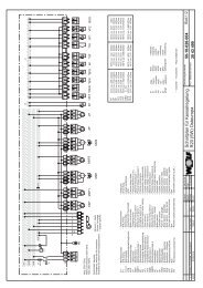
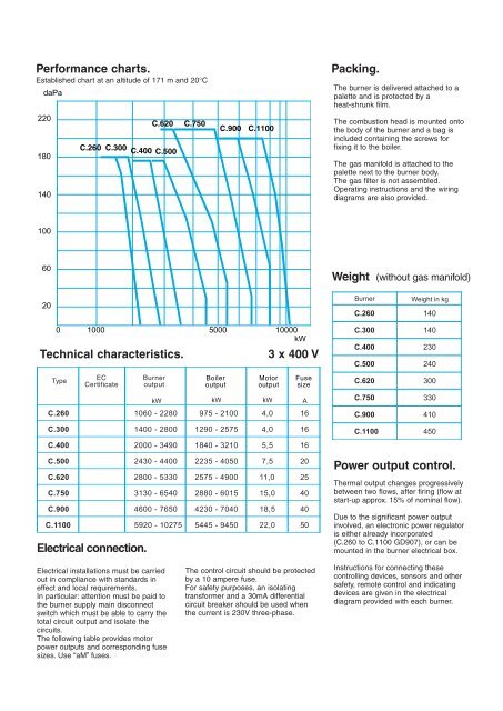
Performance charts.Established chart at an altitude of 171 m and 20°CdaPa220180140<strong>C.260</strong>C.300 C.400 C.500C.620 C.750C.900 <strong>C.1100</strong>Packing.The burner is delivered attached to apalette and is protected by aheat-shrunk film.The combustion head is mounted ontothe body of the burner and a bag isincluded containing the screws forfixing it to the boiler.The gas manifold is attached to thepalette next to the burner body.The gas filter is not assembled.Operating instructions and the wiringdiagrams are also provided.10060Weight (without gas manifold)200Technical characteristics.Type1000 5000 10000kWECCertificateBurneroutputBoileroutput3 x 400 VMotoroutputFusesizekW kW kW A<strong>C.260</strong> 1060 - 2280 975 - 2100 4,0 16Burner<strong>C.260</strong>C.300C.400C.500C.620C.750C.900Weight in kg140140230240300330410C.300 1400 - 2800 1290 - 2575 4,0 16C.400 2000 - 3490 1840 - 3210 5,5 16C.500 2430 - 4400 2235 - 4<strong>050</strong> 7,5 20C.620 2800 - 5330 2575 - 4900 11,0 25C.750 3130 - 6540 2880 - 6015 15,0 40C.900 4600 - 7650 4230 - 7040 18,5 40<strong>C.1100</strong> 5920 - 10275 5445 - 9450 22,0 50Electrical connection.<strong>C.1100</strong> 450Power output control.Thermal output changes progressivelybetween two flows, after firing (flow atstart-up approx. 15% of nominal flow).Due to the significant power outputinvolved, an electronic power regulatoris either already incorporated(<strong>C.260</strong> to <strong>C.1100</strong> GD907), or can bemounted in the burner electrical box.Electrical installations must be carriedout in compliance with standards ineffect and local requirements.In particular: attention must be paid tothe burner supply main disconnectswitch which must be able to carry thetotal circuit output and isolate thecircuits.The following table provides motorpower outputs and corresponding fusesizes. Use “aM” fuses.The control circuit should be protectedby a 10 ampere fuse.For safety purposes, an isolatingtransformer and a 30mA differentialcircuit breaker should be used whenthe current is 230V three-phase.Instructions for connecting thesecontrolling devices, sensors and othersafety, remote control and indicatingdevices are given in the electricaldiagram provided with each burner.