C.260 C.1100 1 050
C.260 C.1100 1 050
C.260 C.1100 1 050

Create successful ePaper yourself
Turn your PDF publications into a flip-book with our unique Google optimized e-Paper software.
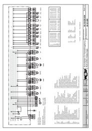
Gas connection.The cross section of the pipes iscalculated in such a way that thepressure drops no more than 10 to15mbar and that the pressure reducingstation is not disturbed.The diameter of the piping should begreater than the diameter of the filter, ifpossible. For information purposes, thefollowing table contains the gas flowscorresponding to each burner’smaximum output for a gas at 15°C ata barometric pressure of 1013mbar.Gas flowsBurner <strong>C.260</strong> C.300 C.400 C.500 C.620 C.750 C.900 <strong>C.1100</strong>Maximum burner output kW 2.280 2.800 3.490 4.400 5.330 6.540 7.950 10.275Maximum boiler output kW 2.100 2.580 3.210 4.<strong>050</strong> 4.900 6.010 7.310 9.450Natural gas flow m 3 /h 241 296 369 466 564 692 841 1.087Propane gas flow m 3 /h 93 115 143 180 218 268 325 420Hydraulic diagrams.AGP ® systemGasAirGEM ® systemKey:100 Burner101 Gas pressure connector102 Air pressure connector103 Combustion chamberpressure connector120 Air shutter142 Filter151 Main gas manifold153 Valve with proportion regulator154 Safety valve155 Pilot gas manifold (C.620 to <strong>C.1100</strong>)313 Minimum gas pressure switch314 Leak tester349 ServomotorKey:GasAir100 Burner101 Gas pressure connector120 Air shutter150 Gas valve142 Filter151 Main gas manifold153 Valve with proportion regulator154 Safety valve155 Pilot gas manifold (C.620 to <strong>C.1100</strong>)313 Minimum gas pressure switch314 Leak tester349 Servomotor