
Create successful ePaper yourself
Turn your PDF publications into a flip-book with our unique Google optimized e-Paper software.
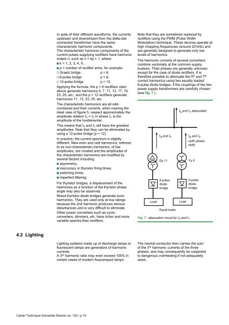
In spite of their different waveforms, the currentsupstream and downstream from the delta-starconnected transformer have the samecharacteristic harmonic components.The characteristic harmonic components of thecurrent pulses supplying rectifiers have harmonicorders n, such as n = kp ± 1, where:c k = 1, 2, 3, 4, 5...c p = number of rectifier arms, for example:v Graetz bridge p = 6,v 6-pulse bridge p = 6,v 12-pulse bridge p = 12.Applying the formula, the p = 6 rectifiers citedabove generate harmonics 5, 7, 11, 13, 17, 19,23, 25, etc., and the p = 12 rectifiers generateharmonics 11, 13, 23, 25, etc.The characteristic harmonics are all oddnumberedand their currents, when nearing theideal case of figure 5, respect approximately theamplitude relation I n = I 1 /n where I 1 is theamplitude of the fundamental.This means that I 5 and I 7 will have the greatestamplitudes. Note that they can be eliminated byusing a 12-pulse bridge (p = 12).In practice, the current spectrum is slightlydifferent. New even and odd harmonics, referredto as non-characteristic harmonics, of lowamplitudes, are created and the amplitudes ofthe characteristic harmonics are modified byseveral factors including:c asymmetry,c inaccuracy in thyristor firing times,c switching times,c imperfect filtering.For thyristor bridges, a displacement of theharmonics as a function of the thyristor phaseangle may also be observed.Mixed thyristor-diode bridges generate evenharmonics. They are used only at low ratingsbecause the 2nd harmonic produces seriousdisturbances and is very difficult to eliminate.Other power converters such as cycloconverters,dimmers, etc. have richer and morevariable spectra than rectifiers.Note that they are sometimes replaced byrectifiers using the PWM (Pulse WidthModulation) technique. These devices operate athigh chopping frequencies (around 20 kHz) andare generally designed to generate only lowlevels of harmonics.The harmonic currents of several converterscombine vectorially at the common supplybusbars. Their phases are generally unknownexcept for the case of diode rectifiers. It istherefore possible to attenuate the 5 th and 7 thcurrent harmonics using two equally loaded6-pulse diode bridges, if the couplings of the twopower supply transformers are carefully chosen(see fig. 7 ).LoadI 5 and I 7Dy 116-pulsediodebridgeEqual loadsI 5 and I 7 attenuatedLoadFig. 7 : attenuation circuit for I 5 and I 7 .I 5 and I 7(with phaseshift)Yy 06-pulsediodebridge4.2 LightingLighting systems made up of discharge lamps orfluorescent lamps are generators of harmoniccurrents.A 3 rd harmonic ratio may even exceed 100% incertain cases of modern fluocompact lamps.The neutral conductor then carries the sumof the 3 rd harmonic currents of the threephases, and may consequently be subjectedto dangerous overheating if not adequatelysized.Cahier Technique <strong>Schneider</strong> <strong>Electric</strong> no. 152 / p.10