
Create successful ePaper yourself
Turn your PDF publications into a flip-book with our unique Google optimized e-Paper software.
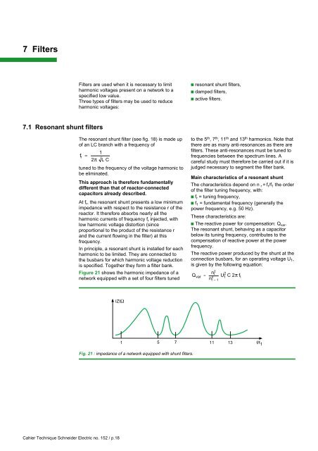
7 FiltersFilters are used when it is necessary to limitharmonic voltages present on a network to aspecified low value.Three types of filters may be used to reduceharmonic voltages:c resonant shunt filters,c damped filters,c active filters.7.1 Resonant shunt filtersThe resonant shunt filter (see fig. 18) is made upof an LC branch with a frequency off r=12 π L Ctuned to the frequency of the voltage harmonic tobe eliminated.This approach is therefore fundamentallydifferent than that of reactor-connectedcapacitors already described.At f r , the resonant shunt presents a low minimumimpedance with respect to the resistance r of thereactor. It therefore absorbs nearly all theharmonic currents of frequency f r injected, withlow harmonic voltage distortion (sinceproportional to the product of the resistance rand the current flowing in the filter) at thisfrequency.In principle, a resonant shunt is installed for eachharmonic to be limited. They are connected tothe busbars for which harmonic voltage reductionis specified. Together they form a filter bank.Figure 21 shows the harmonic impedance of anetwork equipped with a set of four filters tunedto the 5 th , 7 th , 11 th and 13 th harmonics. Note thatthere are as many anti-resonances as there arefilters. These anti-resonances must be tuned tofrequencies between the spectrum lines. Acareful study must therefore be carried out if it isjudged necessary to segment the filter bank.Main characteristics of a resonant shuntThe characteristics depend on n r =f r /f 1 the orderof the filter tuning frequency, with:c f r = tuning frequency,c f 1 = fundamental frequency (generally thepower frequency, e.g. 50 Hz).These characteristics are:c The reactive power for compensation: Q var .The resonant shunt, behaving as a capacitorbelow its tuning frequency, contributes to thecompensation of reactive power at the powerfrequency.The reactive power produced by the shunt at theconnection busbars, for an operating voltage U 1 ,is given by the following equation:Q n r 2var = U1 22C 2πf1nr – 1IZIΩ1 5 7 11 13 f/f 1Fig. 21 : impedance of a network equipped with shunt filters.Cahier Technique <strong>Schneider</strong> <strong>Electric</strong> no. 152 / p.18