
You also want an ePaper? Increase the reach of your titles
YUMPU automatically turns print PDFs into web optimized ePapers that Google loves.
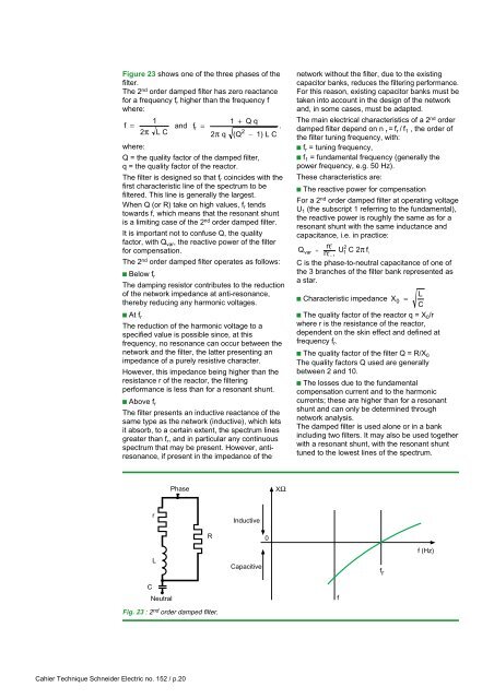
Figure 23 shows one of the three phases of thefilter.The 2 nd order damped filter has zero reactancefor a frequency f r higher than the frequency fwhere:11 + Q qf =and f r =.2 π L C22π q (Q – 1) L Cwhere:Q = the quality factor of the damped filter,q = the quality factor of the reactor.The filter is designed so that f r coincides with thefirst characteristic line of the spectrum to befiltered. This line is generally the largest.When Q (or R) take on high values, f r tendstowards f, which means that the resonant shuntis a limiting case of the 2 nd order damped filter.It is important not to confuse Q, the qualityfactor, with Q var , the reactive power of the filterfor compensation.The 2 nd order damped filter operates as follows:c Below f rThe damping resistor contributes to the reductionof the network impedance at anti-resonance,thereby reducing any harmonic voltages.c At f rThe reduction of the harmonic voltage to aspecified value is possible since, at thisfrequency, no resonance can occur between thenetwork and the filter, the latter presenting animpedance of a purely resistive character.However, this impedance being higher than theresistance r of the reactor, the filteringperformance is less than for a resonant shunt.c Above f rThe filter presents an inductive reactance of thesame type as the network (inductive), which letsit absorb, to a certain extent, the spectrum linesgreater than f r , and in particular any continuousspectrum that may be present. However, antiresonance,if present in the impedance of thenetwork without the filter, due to the existingcapacitor banks, reduces the filtering performance.For this reason, existing capacitor banks must betaken into account in the design of the networkand, in some cases, must be adapted.The main electrical characteristics of a 2 nd orderdamped filter depend on n r =f r / f 1 , the order ofthe filter tuning frequency, with:c f r = tuning frequency,c f 1 = fundamental frequency (generally thepower frequency, e.g. 50 Hz).These characteristics are:c The reactive power for compensationFor a 2 nd order damped filter at operating voltageU 1 (the subscript 1 referring to the fundamental),the reactive power is roughly the same as for aresonant shunt with the same inductance andcapacitance, i.e. in practice:2nr2Qvar = 2nU1C 2πf1r – 1C is the phase-to-neutral capacitance of one ofthe 3 branches of the filter bank represented asa star.Lc Characteristic impedance X 0 =Cc The quality factor of the reactor q = X 0 /rwhere r is the resistance of the reactor,dependent on the skin effect and defined atfrequency f r .c The quality factor of the filter Q = R/X 0The quality factors Q used are generallybetween 2 and 10.c The losses due to the fundamentalcompensation current and to the harmoniccurrents; these are higher than for a resonantshunt and can only be determined throughnetwork analysis.The damped filter is used alone or in a bankincluding two filters. It may also be used togetherwith a resonant shunt, with the resonant shunttuned to the lowest lines of the spectrum.PhaseXΩrInductiveR0LCapacitivef rf (Hz)CNeutralfFig. 23 : 2 nd order damped filter.Cahier Technique <strong>Schneider</strong> <strong>Electric</strong> no. 152 / p.20