
Create successful ePaper yourself
Turn your PDF publications into a flip-book with our unique Google optimized e-Paper software.
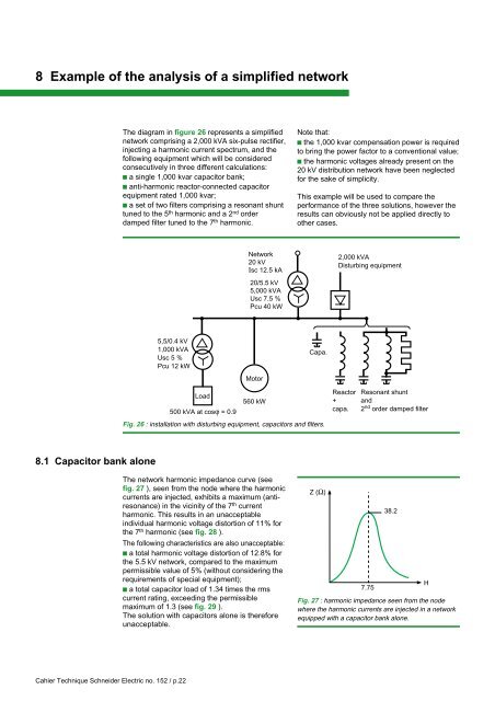
8 Example of the analysis of a simplified networkThe diagram in figure 26 represents a simplifiednetwork comprising a 2,000 kVA six-pulse rectifier,injecting a harmonic current spectrum, and thefollowing equipment which will be consideredconsecutively in three different calculations:c a single 1,000 kvar capacitor bank;c anti-harmonic reactor-connected capacitorequipment rated 1,000 kvar;c a set of two filters comprising a resonant shunttuned to the 5 th harmonic and a 2 nd orderdamped filter tuned to the 7 th harmonic.Note that:c the 1,000 kvar compensation power is requiredto bring the power factor to a conventional value;c the harmonic voltages already present on the20 kV distribution network have been neglectedfor the sake of simplicity.This example will be used to compare theperformance of the three solutions, however theresults can obviously not be applied directly toother cases.Network20 kVIsc 12.5 kA2,000 kVADisturbing equipment20/5.5 kV5,000 kVAUsc 7.5 %Pcu 40 kW5,5/0.4 kV1,000 kVAUsc 5 %Pcu 12 kWCapa.Load500 kVA at cosϕ = 0.9Motor560 kWReactor+capa.Resonant shuntand2 nd order damped filterFig. 26 : installation with disturbing equipment, capacitors and filters.8.1 Capacitor bank aloneThe network harmonic impedance curve (seefig. 27 ), seen from the node where the harmoniccurrents are injected, exhibits a maximum (antiresonance)in the vicinity of the 7 th currentharmonic. This results in an unacceptableindividual harmonic voltage distortion of 11% forthe 7 th harmonic (see fig. 28 ).The following characteristics are also unacceptable:c a total harmonic voltage distortion of 12.8% forthe 5.5 kV network, compared to the maximumpermissible value of 5% (without considering therequirements of special equipment);c a total capacitor load of 1.34 times the rmscurrent rating, exceeding the permissiblemaximum of 1.3 (see fig. 29 ).The solution with capacitors alone is thereforeunacceptable.Z (Ω)7.7538.2Fig. 27 : harmonic impedance seen from the nodewhere the harmonic currents are injected in a networkequipped with a capacitor bank alone.HCahier Technique <strong>Schneider</strong> <strong>Electric</strong> no. 152 / p.22