
Create successful ePaper yourself
Turn your PDF publications into a flip-book with our unique Google optimized e-Paper software.
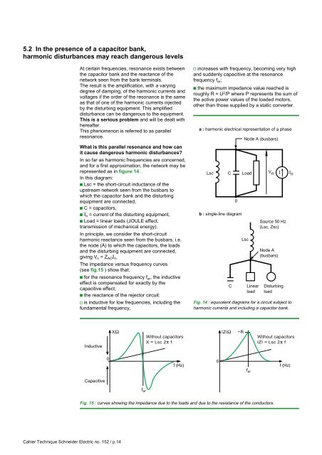
5.2 In the presence of a capacitor bank,harmonic disturbances may reach dangerous levelsAt certain frequencies, resonance exists betweenthe capacitor bank and the reactance of thenetwork seen from the bank terminals.The result is the amplification, with a varyingdegree of damping, of the harmonic currents andvoltages if the order of the resonance is the sameas that of one of the harmonic currents injectedby the disturbing equipment. This amplifieddisturbance can be dangerous to the equipment.This is a serious problem and will be dealt withhereafter.This phenomenon is referred to as parallelresonance.What is this parallel resonance and how canit cause dangerous harmonic disturbances?In so far as harmonic frequencies are concerned,and for a first approximation, the network may berepresented as in figure 14 .In this diagram:c Lsc = the short-circuit inductance of theupstream network seen from the busbars towhich the capacitor bank and the disturbingequipment are connected,c C = capacitors,c I n = current of the disturbing equipment,c Load = linear loads (JOULE effect,transmission of mechanical energy).In principle, we consider the short-circuitharmonic reactance seen from the busbars, i.e.the node (A) to which the capacitors, the loadsand the disturbing equipment are connected,giving V n = Z AO I n .The impedance versus frequency curves(see fig.15 ) show that:c for the resonance frequency f ar , the inductiveeffect is compensated for exactly by thecapacitive effect;c the reactance of the rejector circuit:v is inductive for low frequencies, including thefundamental frequency,v increases with frequency, becoming very highand suddenly capacitive at the resonancefrequency f ar ;c the maximum impedance value reached isroughly R = U 2 /P where P represents the sum ofthe active power values of the loaded motors,other than those supplied by a static converter.a : harmonic electrical representation of a phaseLscC0b : single-line diagramCNode A (busbars)LoadLscLinearloadV nSource 50 Hz(Lsc, Zsc)Node A(busbars)IDisturbingloadFig. 14 : equivalent diagrams for a circuit subject toharmonic currents and including a capacitor bank.I nInductiveCapacitive0XΩWithout capacitorsX = Lsc 2π ff arf (Hz)0IZIΩ ~Rf arWithout capacitorsIZI = Lsc 2π ff (Hz)Fig. 15 : curves showing the impedance due to the loads and due to the resistance of the conductors.Cahier Technique <strong>Schneider</strong> <strong>Electric</strong> no. 152 / p.14