56701-IPI only
56701-IPI only
56701-IPI only

You also want an ePaper? Increase the reach of your titles
YUMPU automatically turns print PDFs into web optimized ePapers that Google loves.
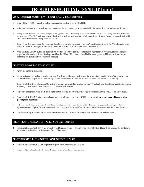
TROUBLESHOOTING (<strong>56701</strong>-<strong>IPI</strong> <strong>only</strong>)MAIN CONTROL MODULE WILL NOT LEARN TRANSMITTEREnsure REMOTE/OFF switch on side of main control module is set to REMOTE.Make sure batteries in both the hand held remote and backup battery pack are installed in the proper direction and are not drained.Verify hand held remote indicates a signal is being sent. The LCD display should indicate ON or OFF depending on which button isbeing pressed. The LED indicator should illuminate on wall transmitters and on/off transmitters. Buttons should be pressed and held for1 to 2 seconds to ensure a complete signal is sent.Ensure 4-pin lead-set is securely connected from battery pack to main control module‟s AUX connection. If the A/C adapter is used,check that leads from adapter are securely connected to POWER terminals on main control module.Press and hold LEARN button on main control module for approximately 10 seconds to clear memory (you should hear a series ofbeeps from the receiver), immediately press either the ON or OFF button on hand held remote (you should hear a series of beepsindicating the transmitter code has been learned).PILOT WILL NOT LIGHT / STAY LITVerify gas supply is turned on.Verify main control module is receiving signal from hand held remote by listening for a beep from receiver when ON is pressed onhand held remote. If you do not hear a beep, ensure main control module has learned the hand held remote. (See above).Ensure black lead from pilot assembly igniter is securely connected to terminal labeled “I” and red lead from flame rectification sensoris securely connected terminal labeled “S” on main control module.Make sure orange and white leads from main control module are securely connected to terminals labeled “PILOT” on valve body.Ensure black GROUND wire is securely connected to tab located next to ON/OFF toggle switch. A proper ground is essential tospark igniter operation.Make sure pilot flame is in contact with flame rectification sensor on pilot assembly. This valve is equipped with a pilot flameadjustment screw. If pilot flame is too small it will not contact flame rectification sensor and will not complete the safety circuit.Check continuity of pilot on valve. Remove wire connector. If there is no continuity on pin terminals, replace valve.PILOT FLAME ALWAYS ON / WILL NOT EXTINGUISHEnsure continuous pilot icon is not present in LCD screen. If icon is present, press PILOT button. This will de-activate the continuouspilot feature and the icon will disappear from LCD screen.PILOT BURNING BUT IGNITOR CONTINUES TO SPARKCheck that flame sensor is fully impinged by pilot flame. If needed, adjust pilot.Check end-to-end continuity of sensor. If sensor has continuity, replace module.PAGE 56