COMMONWEALTH OF MASSACHUSETTS REQUIREMENTSNOTE: The following requirements reference various Massachusetts and national codes not contained in this manual.For all sidewall horizontally vented gas fueled equipment installed in every dwelling, building or structure used in whole or in part for residential purposes,including those owned or operated by the Commonwealth and where the side wall exhaust vent termination is less than (7) feet above finished grade in thearea of the venting, including but not limited to decks and porches, the following requirements shall be satisfied:INSTALLATION OF CARBON MONOXIDE DETECTORSAt time of installation of side wall horizontally vented gas fueled equipment, the installing plumber or gas-fitter shall observe that a hard wired carbon monoxidedetector with an alarm and battery back-up is installed on the floor level where the gas equipment is to be installed. In addition, the installing plumberor gas-fitter shall observe that a battery operated or hard wired carbon monoxide detector is installed on each additional level of the dwelling, building orstructure served by the side wall horizontal vented gas fueled equipment. It shall be the responsibility of the property owner to secure the services of qualifiedlicensed professionals for the installation of hard wired carbon monoxide detectors.In the event that the side wall horizontally vented gas fueled equipment is installed in a crawl space or attic, the hard wired carbon monoxide detector withalarm and battery back-up may be installed on the next adjacent floor level.In the event that the requirements of this subdivision can not be met at the time of completion of installation, the owner shall have a period of thirty (30) daysto comply with the above requirements; provided, however, that during said thirty (30) day period, a battery operated carbon monoxide detector with analarm shall be installed.APPROVED CARBON MONOXIDE DETECTORSEach carbon monoxide detector as required in accordance with the above provisions shall comply with NFPA 720 and be ANSI/UL 2034 listed and IAScertified.SIGNAGEA metal or plastic identification plate shall be permanently mounted to the exterior of the building at a minimum of eight (8) feet above grade directly in linewith the exhaust vent terminal for the horizontally vented gas fueled heating appliance or equipment. The sign shall read, in print no less the one-half inch(1/2) in size, “GAS VENT DIRECTLY BELOW. KEEP CLEAR OF ALL OBSTRUCTIONS”.INSPECTIONThe state or local gas inspector of the side wall horizontally vented gas fueled equipment shall not approve the installation unless, upon inspection, theinspector observes carbon monoxide detectors and signage installed in accordance with the provisions of 248 CMR 5.08 (2) (a) 1 through 4.EXEMPTIONSThe following equipment is exempt from 248 CMR 5.08 (2) (a) 1 through 4:The equipment listed in Chapter 10 entitled “Equipment Not Required To BeVented” in the most current edition of NFPA 54 as adopted by the Board; and Product Approved side wall horizontally vented gas fueled equipment installedin a room or structure separate from the dwelling, building or structure used in whole or in part for residential purposes.MANUFACTURER REQUIREMENTS - GAS EQUIPMENT VENTING SYSTEM PROVIDEDWhen the manufacturer of Product Approved side wall horizontally vented gas equipment provides a venting system design or venting system componentswith the equipment, the instructions provided by the manufacturer for installation of the equipment and the venting system shall include:Detailed instructions for the installation of the venting system design or the venting system components; andA complete parts list for the venting system design or venting system.MANUFACTURER REQUIREMENTS - GAS EQUIPMENT VENTING SYSTEM NOT PROVIDEDWhen the manufacturer of Product Approved side wall horizontally vented gas equipment does not provide the parts for venting the flue gases, but identifies“special venting systems”, the following requirements shall be satisfied by the manufacturer:The referenced “special venting systems” instructions shall be included with the appliance or equipment installation instructions and;The “special venting systems” shall be Product Approved by the Board, and the instructions for that system shall include a parts list and detailedinstallation instructions.A copy of all installation instructions for all Product Approved side wall horizontally vented gas fueled equipment, all venting instructions, all parts lists forventing instructions, and/or all venting design instructions shall remain with the appliance or equipment at the completion of the installation.PAGE 5
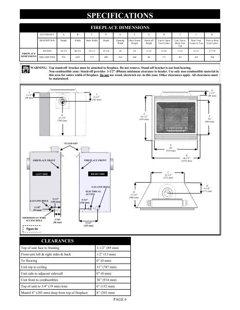
SPECIFICATIONSFIREPLACE DIMENSIONSLETTER KEY A B C D E F G H I J KDESCRIPTION Height Width Back Width Depth OpeningWidthGlass FrameHeightStand-offHeightTop to UpperVent CenterUnit Top toBack VentTopRear VentCenter to TopFloor to RearVent CenterFIREPLACEDIMENSIONSINCHES 34-1/2 40-3/4 22-1/2 15-3/4 36 26 3-1/2 6-3/4 3-1/2 6-1/2 27-7/8MILLIMETERS 876 1035 572 400 914 660 89 171 89 165 708WARNING: Top stand-off bracket must be attached to fireplace. Do not remove. Stand-off bracket is not load bearing.Non-combustible zone: Stand-off provides 3-1/2” (89mm) minimum clearance to header. Use <strong>only</strong> non-combustible material inthis area for entire width of fireplace. Do not use wood, sheetrock etc. in this zone. Other clearances apply. All clearances mustbe maintained.I3-1/2”(89 mm)J6-1/2”(165 mm)G3-1/2”(89 mm)K27-7/8”(708 mm)A34-1/2”(876 mm)F26”(660 mm)STAND-OFFE36”(914 mm)FIREPLACE FRONTFIREPLACE FRONTB40-3/4”(1035 mm)LEFT SIDERIGHT SIDEC22-1/2”(572 mm)GAS LINE HOLE5-1/2”(140 mm)5-3/4”(146 mm)GAS LINE HOLEELECTRICALACCESSD15-3/4”(400 mm)H6-3/4”(171 mm)2-1/8”(54 mm)THERMOSTAT WIREACCESS HOLEFigure 6a3-3/8”(86 mm)9-1/4”(235 mm)CLEARANCESTop of unit face to framingFrom unit left & right sides & backTo flooringUnit top to ceilingUnit side to adjacent sidewallUnit front to combustiblesTop of unit to 3/4” (19 mm) trimMantel 8” (203 mm) deep from top of fireplace3-1/2” (89 mm)1/2” (13 mm)0” (0 mm)31” (787 mm)0” (0 mm)36” (914 mm)6” (152 mm)8” (203 mm)PAGE 6